

Shuriken
-
Posts
973 -
Joined
-
Last visited
-
Days Won
11
Content Type
Profiles
Forums
Blogs
Gallery
Posts posted by Shuriken
-
-
The BOM is online on the WIKI now :)
Cool thanks...i took the liberty of adding a public shopping cart to the page.
-
I kinda want to order my parts so i am able to start. I haven't found any partlist for the SSM2164 VCA yet. I guess Seppoman hasn't come round to it yet. So far i deducted from the photo's the following:
P1,P2,P3,P4 - PV36W - 10K Precision Trimmer
IC1 - SSM2164
IC2,IC3 - TL074CN OpAmp
IC Socket - 2x 14
IC Socket - 1x 16
Single Header 3 Pin x 5
Double Header 8 Pin x 1
-
I noticed you fixed them today. So tell us your secret :ahappy:
-
I had to drive to the otherside of town due to some mailman mix up. But is was well worth it. Thanks Thomas :thumbsup:
:heart: the black PCB.
-
Yes, first of all it was ill and now its died. :no:
Plus side is that now I can get on and do some other things whilst I wait for all the bits to arrive and when it does, the CS is there waiting for it.
It was really good whilst it lasted!
I see Mike has OPL sets but no sound chips.
S
You could try the which is currently underway. I do have a YMF262 which is a pull. But you won't get very far withit without any YAC512.
-
We did some more troubleshooting on this Core32, and we found some new things out. First off, all the voltage checks are fine, and we replaced the crystal... which didn't do the trick.
Next we stuffed J27, and what we got was a solid green LED. This leads me to think that the main Core32 software has crashed. My understanding is that we need a JTAG or a CAN interface, both of which I have very little knowledge of. I am going to do some research when I get some free time, but if anyone has any suggestions I'm all eyes.
Also, if we do indeed need to burn the Chip again and someone has the proper hardware I'd be very thankful if I could send the Core32 off to you.
Cheers,
Grizz
Have you read this page? http://www.ucapps.de/mios32_bootstrap_experts.html
There is some links to JTAG Adapters.
-
Yes replacing the DAC first makes sense, but guess what I don't have any spares of?
I'll post in the Fleamarket section too, but if anyone has any spare sets of chips, (think I'll do another one of these anyway) please let me know.
I do have a spare YMF262 so maybe that will get replaced first, guess its a 50/50 chance.
Thanks again
S
I see you killed you OPL3 board desoldering. I sure know how that feels :whistle:
-
Thanks for the inputs.
So there seems to be general agreement that the modular approach is the way to go for a newbie, and that it'll be the easiest to fit in the C64 case. I would have thought it'd be the other way around, due to the compact size of the MB-6582 boards.
The case is of the later generation (1990?), which if I'm not mistaken contains an 8580. So I got some bits to get me started. It irks me that I'm going to murder a perfectly functioning C64, but on the other hand I never use it. It just sits around gathering dust. Still, I apologize to the C64 community... I'm sorry, ok?
As for the control surface, I can live with only having access to the various parameters via the PC (or the Yamaha RM1Xx) for now, but I do love me some knob twiddlin', so that's a must have in the months to come.
Open your Commodore up to be sure what type it is. You wont be murdering it...just crippling :whistle: The SID chip is in a socket.
-
1xSID, 1xCORE will give you what you want, but won't easily let you upgrade to MB6582 (well you can use the PIC and the SID chip...but that's it)
The MB6582 won't fit a C64 case (first model) it might fit the second model but it would be a snug fit.
I think you should stick with the 1xSID, 1xCORE and gain some experience.
-
Not much you can do to test the components separatly.
I would suggest replacing one DAC. If you then still have distorted sound on that channel, replace the YMF262.
-
As my MB6582 is nearing completion, i need to start building a decent PSU.
At first i thought about using Northernligthx design but there are some flaws. I spoke to him and he told me his design isn't working well at the moment.
So i decided to make my own design taking his as inspiration. I want to use a 2 x 12V Transformer:

On another electronics forum i was warned about latch-up. So i want to change the design and add a latchup protection. It's supposed to be done by adding some diodes. But i am not sure how.
So i would be helped if anybody could tell me how.
-
Upload the testone app and check voltages. Especially 5V. Check across different components.
Also how long are your leads from Core to OPL3 board?
-
Should work. Its not compatible with certain types of plastic. Those will probably dissolve. Probably not recommended to spray it on switches and pots. But those are usually on the otherside of the pcb.
99% Isopropyl alcohol will also do the trick.
-
I think you should put these extra features on a nice-to-have list. And focus on the main concept. This will be hard enough to realize.
-
At this point the front panel design is something which comes from Hurolola. As it is, it doesn't justify using a Core32. A bunch of knobs can be realized with the use of a Midibox64 as Alexk has so elegantly showed us with his
I agree that with compromising on all fronts you end up with something that excel at nothing. The controller keyboard i have at the moment has the same problem you mentioned. It has a bunch of knobs, but i can never remember which one is for what :frantics: , especially when trying to control different synths with it.
My idea was to create a control interface something looking more like the Arturia Origin. Less knobs and more flexible.

It would be nice though to create something that would appeal to a lot of people. So any input is appreciated.
-
I have a question about the diodes. As the choice for the 1N4008 seems a bit odd to me.
The 1N4008 is 1A only. Since the current draw is theoratically 3A (7812,7809 and 7805 combined) wouldn't it be more logical to choose the 1N5401 which is rated up to 3A?
-
Thnx for the update. Just take your time. It will get here when it gets here :thumbsup:
-
I am OK. Midibox UC is not intuitive/synth oriented enough for me.
I would rather set back something more inspired by the CreamWare/SonicCore ASB sound modules but merging them alltogether.
As i said its only the concept. The design isn't to my liking either.
A few questions I am wondering about merging control:
- Merge Minimax Osc 3 and other plug-ins LFO 1 ?
- Merge Prodyssey S&H and LightWave LFO 2 or Free EG ?
I see 3 types of thing among these plugs:
- Audio flow control elements: Osc/Mix/Filter/Amp/Pan + FX (Chorus+Delay)
- "Fixed" control elements including enveloppe generator, LFO and keyboard note
- "RealTime" control elements including Velocity, AfterTouch, Modulation Wheel
Here is a wild idea. Consider making a fixed number of controls which are common for all the synths. The variable ones could be the knobs around the display area. The label will be shown in the display as you switch profiles.
I had a bit of fiddling with the front panel designer. The DOGXL display is just big enough to fit 4 knobs on a side. So 8 knobs or 16 if you also choose to populate bottom en top.
-
whowhopwhop !!!
i want that :
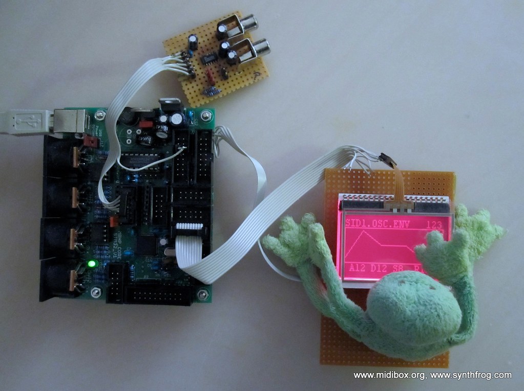
so TK, what's your trick ? :w00t:
My guess is the display in the picture is a DOGXL160-7 with touchpanel.
-
It would be good to build it for both internal ASX board or external device (more flexible).
I totally agree. It basically would be a synth control surface. If we make it programmable, people could alter the key/knob bindings for their own needs. As i said in the other topic we are basically taking the concept of the Midibox UC and recreate it for Core32. Hopefully we can improve on the design, which isn't ideal.
In the meanwhile i started building my Core32 yesterday. But didn't get passed the stage of placing the 12 Mhz Crystal. I found out i forgot to order the two caps required :pinch:
Update: With a little bit if scavaging i managed to find all the parts.
-
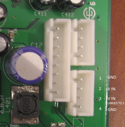
Details on the Use Audio Plugiator ASX board:
Technical:
CPU - ATMega32
DPS - Analog Devices SHARC 21363
Internal Connections:
9 Volt DC Powerconnector
Midi IN
External Connections:
USB - B
MIC IN
Headphone Out
Line Out Left
Line Out Right
Physical Dimensions:
95 x 130 mm
Here is a closeup of the internal powerconnector:
-
Been awhile since i posted. I am going to start building my Core 32 tomorrow. I had some trouble getting my hands on the LF33CV.
Anyway, maybe it would be a good idea to either ask a mod to rename this topic or start a new one? The current title might give people the wrong idea. Perhaps that way we can get more people interested.
-
Here is the D50 Service Manual
It seems there is some people on electro-music.com who seem to know a lot about the D50 techically. Maybe you can try and ask there.
-
Hi ,
After years of sleep I powered on my Roland D50 .
It works fine...very fine but aftertouch ( from its keyboard ) do not responds. :no:
From MIDI aftertouch works normally so it is a keyboard sensors problem.
In the net i read that it is a common problem on some Roland products ( JD800,D50 )
and it is caused from resistor in the pressure sensor amplifier that change its value
in the years.
Is anybody experienced of this or knows a link useful for solving this problem? :console:
Best Regards
Antix
This maybe? http://www.bustedgear.com/repair_Roland_d50_key_contacts_2.html
SDcard Types?
in Parts Questions
Posted
It's not a big mystery.
There are just two defining features: Size and Speed
I think the size part is pretty obvious. As for the speed:
The following are the ratings of some currently available cards:
* Class 2: 16 Mbit/s (2 MB/s)
* Class 4: 32 Mbit/s (4 MB/s)
* Class 6: 48 Mbit/s (6 MB/s)
* Class 10: 80 Mbit/s (10 MB/s)
The highspeed ones are used in camera's where speed really matters. These are a bit more expensive. The Class 2 and 4 ones are similarly priced. So either of those should do the trick as i don't think speed is a big issue in this case. For size you will probably do fine with a 1 GB one. I don't think you can buy much smaller ones these days.