

Rics
-
Posts
69 -
Joined
-
Last visited
Content Type
Profiles
Forums
Blogs
Gallery
Everything posted by Rics
-
Ok, i did some tests with pull-up resistors over the J16 and J19 jumpers and the jitter still remained. So i'm now sure that this is coming from my small BLM test module...and more worst, i leaved some pins of the 74hc595 and 74hc165 opened! :excl:
-
Thank you as ever Tim! Later i will try with the pull-up and i will do a report. :thumbsup:
-
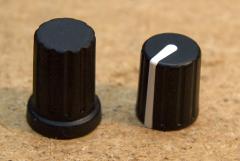 Do you know a place where i can find the P401 knob?
 -
Here i'm with the fixing show! Ok, i've replaced the J8/J9 network resistor with a new one, i've placed all the resistor networks where required, J15A-B-C clamped to ground and now the behaviour is returned as before! Also with the lcd working now! What i don't know how to do is the J16 and J19 ground clamping: i've to put only the serial SI and SO to VS? The SC, RC1 and RC2 pins? What i don't get now are the startup messages that mios studio reports on the mios midi in: I start the Core32 with a BLM test module connected. This test module have one 74HC165 and two 74HC595 ic's, three buttons and three single color led's (i don't want to build an entire module for testing purpose). The buttons and the leds common are all placed on J3 C0 via a bc337 from IC2 (74HC595) and respectively I0-I1-I2 from IC1 (74HC165) for the buttons + G0-G1-G2 from IC3 for the leds (74HC165). I haven't used IC4 because i'm not using duo-leds. That's what i've on the mios_studio monitor (i used pastebin because the messages list is too long) Messages list It starts with a long series of note on/note off messages on the first four channels, ch.0-ch.1-ch.2-ch.3 (0x90-0x91-0x92-0x93), with note values B-2 A-2 C-0 B-1 (07-06-0f-0e) and velocity values between 0 and 127 (00-7f). After 1-2 minutes of these messages i've the mios_studio monitor showing in a regular cadence the sysex message f0 00 00 7e 4e 00 01 10 10 02 01 01 01 f7 with no more the previous note on / note off messages. The leds and the buttons work fine, also when the note on / note off messages are show in the mios_studio monitor. Perhaps these messages are coming because the other BLM test module IC inputs and outputs aren't connected? PS I think that i'm going a bit off topic, perhaps i've to put this last post to my
-
Ok, i swapped a pair of resistor network and now the lcd is working fine! But a problem go away and another come up! Now, if i connect my small blm module, that worked until before this resistor swap, a lot of random messages are sent to the leds of my blm test module (3 leds). I've all the analog inputs clamped to ground, but this don't stop the random messages downhill. Without the blm module connected to J8/J9 i've this sysex message: [15026.730] f0 00 00 7e 4e 00 01 10 10 02 01 01 01 f7 Don't know what mean this. Then, after the connect of the blm module i have, between the random messages, these sysex messages: [15267.324] f0 00 00 7e 32 00 0f 4d 49 4f 53 33 32 f7 [15267.327] f0 00 00 7e 32 00 0f 4d 42 48 50 5f 43 4f 52 45 5f 53 54 4d 33 32 f7 [15267.330] f0 00 00 7e 32 00 0f 53 54 4d 33 32 46 31 30 78 f7 [15267.330] 92 0a 00 [15267.333] f0 00 00 7e 32 00 0f 30 30 30 30 30 30 30 30 f7 [15267.336] f0 00 00 7e 32 00 0f 33 30 46 46 45 39 38 44 33 31 34 42 33 34 33 34 37 36 32 35 31 39 34 33 f7 [15267.339] f0 00 00 7e 32 00 0f 35 32 34 32 38 38 f7 [15267.340] 93 0f 00 [15267.342] f0 00 00 7e 32 00 0f 36 37 31 30 37 38 34 30 f7 [15267.345] f0 00 00 7e 32 00 0f 42 4c 4d 5f 53 43 41 4c 41 52 20 56 31 2e 30 f7 [15267.348] f0 00 00 7e 32 00 0f 28 43 29 20 32 30 31 30 20 54 2e 4b 6c 6f 73 65 f7 Don't know what means also this. Keep in mind that at the moment i have R32 resistor network not placed, but also J19 isn't used. J16 isn't used and also the display at the moment isn't used. The only resistor network placed are the R31 and R2, the other aren't placed. J5A-B-C are all ground clamped. Concluding i can't find the source of these random messages, i've the doubt that can be at the blm module as is done over a veroboard with ribbon cable wires. (And also because if i disconnect it from the core, no more random messages appears over the mios_studio) What i don't understand is that before the resistor networks unsoldering and resoldering all worked fine.
-
You know our Tim "nameexchange" issue! :tongue: (Sincerely this mistake fitted well with the Tim/Mike name exchange, so i took advantage....but the real thing is i wrote that post when I had just woken up! :blush: )
-
Thank you for the reply Thorsten Tim, today i'm away from home (:brr:), so i've not the possibility to do a check. This evening i will check that R33, now i've the doubt that i've swapped one network with another. Aaah, the rush to test a blm module...:blush:
-
2nd update: I've checked another time the connections, and the lcd wasn't illuminated because the pins 15 and 16, respectively B+ and B- were swapped. I went with closed eyes about the 1:1 pins scheme with the core32. So i took the occasion to recheck all the pins, and seems that were all right except the two B+ and B- immediately fixed. By the way the black row still remain and as before, the P1 trimmer luminosity don't do anything, i've modified the P1 value but the illumination (now working after the B+ & B- swap) remain the same, no variations with the trimmer variation. P2 trimmer, for contrast, work fine. Stille remain that on firing up, no system messages were show, only that black row. At the moment i've the BLM app uploaded. I've tried also with the tutorial#20, but i have the same behaviour. I'm 99% (i leave 1% to murphy's law) sure that the connection now are correct...without apps uploaded, a minimum of initializing data at the startup must come on the display? All the core32 apps support clcd displays? Last question, could be something related to the R33 resistor array?
-
Update: I've reconnected the LCD to the pic core and is working fine. Then i've reconnected it to the core32 and it isn't working, black row as ever.
-
Ok, today i i got some ribbon cable and a pair of connectors and i've did the connections like the ones found here: I've compiled and uploaded the MidiBox SEQ V4.0 and then did a power cycle via usb. The LCD still remained as before, black row. What i noticed is that the P2 contrast trimmer do his work, in fact i see the black row fading in and fading out. But the P1 Luminance trimmer isn't working, to be more precise, as i fire up via usb the module, the LCD isn't backlighted, also when i modify the P1 Luminance trimmer no backlight is going on. I'll do another ribbon cable to reconnect the lcd to the pic core to see if it is working fine. Later i'll post infos about this last test. Thank you all for the support!
-
Well, it's just the picture that's upside down! Btw here it is the datasheet: Link
-
Two days ago i've received the smashtv core32 pcb and parts, i've builded it and then i've connected it via usb to my mac laptop. I've then opened mios studio, uploaded the BLM app and connected to the DIN/DOUT, J8/J9, socket a small BLM module to do some tests. Got all working fine. Then i had an old 2*20 characters display, used with a PIC Core, this display was one of these that smashtv sells some years ago. So, i've changed the pins order like requested on the new core32, i've then checked all the connections with a tester to be sure and only then i've fired up via usb my core32. the result was a black row on the led, like the following picture: After this, i've tried to do a Mios upload, i've downloaded the file on this page, the mios studio rebooted the core32 and then, on firing up, the result was the same, a black row. No system messages, nor booting or initializing messages. As soon i connect the core32 to the usb, that black row appear. Now i don't know if i have to code and upload something more, i thought that like in the pic core, also if no app were loaded, a welcome message from the mios were printed on the lcd. PS I've already did a search over the forum, but sincerely i haven't found something useful to solve my problem.
-
Veramente no, è che ogni tanto mi sono collegato su skype ma non ti ho mai visto online...anche se io in questi giorni non l'ho aperto molto. Domani staro' online tutto il giorno!
-
Thank you for the tip! But i don't know at which files i have to put my eyes, i know that i have into the trunk folder two folders, apps and modules. In the apps i have, under controllers, the blm_scalar app, and into modules the blm_scalar driver. Sincerely i don't know the first thing that i've to do, yes, i have to study about DIN_BLM_NotifyToggle, but where i get infos about it? It's all in the readme.txt and in the comments of the files? Who calls the DIN_BLM_NotifyToggle? Where it get datas? Any tip is appreciated, in the meantime i'll do some searches into the programmers forum to understand more basics.
-
Yes, i admit, i'm slow as a turtle. But as a turtle i've put out my head, and today out in direction to the blog! :) Ok, jokes apart, in the previous step i've explaned how to get installed the needed tools to compile apps for our beloved Core controller, in this third step we will see how to get the SVN repository and then how to get and app compiled and ready as an .hex file to upload to our Pic Core, or Core32. First thing is opening the Terminal. Since the last step i assume that we get familiar with the Terminal window so i'll not explain where and how find it in our Macs! Once you have the terminal opened, go to your home folder. Usually when you open Terminal you're already on the Home folder, and you'll see your mac login name on the left of the cursor. Just type ls and hit return. You'll see a list of files and folder, open via finder your home folder, if you see that the files are the same you are surely in the home folder with the terminal. Otherwise you're in another folder and what you have to write in the terminal is the following command cd Users/yourhomename It will bring you to the home folder. Home folder that will be the folder where we will put the mios, or mios32 repository. With Terminal opened write this command svn co svn://svnmios.midibox.org/mios You'll see that the Terminal will start to download all the repository files in a folder called mios in your home directory. We are downloading this repository in the home folder because we will have to set a .profile file needed to the compiling process. I'll explain his purpose later. Ok, when the Terminal have finished the download, we will see a folder called mios in our home with inside it two folders, trunk and playground. We will concentrate on trunk, the place were all what we need for our apps is placed. But, hey, we forgot the SVN32! Simple task, repeat the same command "svn co" but this time with the svn32 address: svn co svn://svnmios.midibox.org/mios32 At the end of the download you'll have the core32 repository, always in the home directory. Now we have both core and core32 repository in our home folder. You should see mios and mios32 folders. Well, start to compile! No. Do you remember the .profile file mentioned just before? We have to edit it so the tools installed in the Step 2 will work flawlessy. Don't ask me more about this, as i'm learning like you and sometimes i know that things must go in this way but i don't know why because i haven't yet understood all. I know that's not brilliant, but at the end i've the compiling process working! :) (i hope to explain better why to modify .profile page as soon as possible!) Let's go on modify our .profile page, you braves! On terminal write this command (be sure that you're in the home folder "/Users/yourhomename", not in another folder like mios or music ): open .profile You'll see a textedit file opened. Put at the top of the file this code if you are using the mios repository: # mios export MIOS_PATH=/mios/trunk export MIOS_BIN_PATH=$MIOS_PATH/bin # mios end Put this code if you are using the mios32 repository: # mios32 export PATH=$PATH:/usr/local/stm32/bin export MIOS32_PATH=/mios32/trunk export MIOS32_BIN_PATH=$MIOS32_PATH/bin export MIOS32_GCC_PREFIX=arm-none-eabi export MIOS32_FAMILY=STM32F10x export MIOS32_PROCESSOR=STM32F103RE export MIOS32_BOARD=MBHP_CORE_STM32 export MIOS32_LCD=clcd # mios32 end If you're using both the repository put this: # mios export MIOS_PATH=/mios/trunk export MIOS_BIN_PATH=$MIOS_PATH/bin # mios end # mios32 export PATH=$PATH:/usr/local/stm32/bin export MIOS32_PATH=/mios32/trunk export MIOS32_BIN_PATH=$MIOS32_PATH/bin export MIOS32_GCC_PREFIX=arm-none-eabi export MIOS32_FAMILY=STM32F10x export MIOS32_PROCESSOR=STM32F103RE export MIOS32_BOARD=MBHP_CORE_STM32 export MIOS32_LCD=clcd # mios32 end Save the file (cmd+S) and then close. Now, to refresh the system with the new .profile file we have to write this in the Terminal window: . ~/.profile Be careful to include also the first dot! Best way copy and paste. ;) Once the .profile file is refreshed we can now go with our terminal to an app folder and try to compile it. But before i advice you to do always a backup of the folder that contains files needed to compile. My workflow is the following: I need to modify and compile the blm_scalar app. I copy the blm_scalar app folder in another backup folder, folder that can be placed anywhere outside the mios, or mios32 folders. I will have in this way an original copy of the svn downloaded one. Now that we have placed the original copy in a secure place we will start to go into our app target folder with the Terminal: When you are in the home folder with the Terminal write this command cd mios/trunk/apps/controllers/blm_scalar You'll be in the blm_scalar folder where all the .c, .h and makefile, needed for compiling, are located. Remember that you must go in an app single folder with Terminal to have the compiling process working. I mean, if you need to compile the midibox64 app, you will ahve to go to the midibox64 folder through the command cd mios/trunk/apps/controllers/midibox64 and so on for the other apps. I advice you to check out the apps and the relative folders path via finder, and then write the needed path in the terminal. Ok, returning to the our folder, blm_scalar, we are ready to compile our target app. You should have in terminal this position: macname:blm_scalar yourhomename$ What you have to do now is simply write in Terminal make The terminal will print out some text and then the prompt will be back. And now? Check out what changed in the folder via the Terminal command ls You can check out what changed also with finder going into the blm_scalar folder. You should see that some files and a folder were created! And....you should see project.hex, our compiled app ready to be uploaded to our core! Ok, now that we had this file how we can upload to our core? Simple, we will upload it using MIOS_Studio! Download it from here, scroll the page to the bottom, you'll find the download links for mac and windows. In the meantime that connect your Core board to your computer via midi, connecting both midi in and midi out. Once the MIOS_Studio is downloaded, place it in your applications folder and then launch it. Click over the browse button, go on the blm_scalar folder located in /"home"/mios/trunk/apps/controllers/blm_scalar, select the project.hex file and click ok. Then click the start button and the progress bar will raise up with the upload of the project.hex file! When finished your core will reboot and in the MIOS_Studio you will see a "ready" text! You have now your app compiled and uploaded! Consider that the same process is valid when you modify apps and the you'll upload them, is the same also if you are working with the mios32 svn. But remember always to backup the apps folders and to check if the svn is updated! I'll write about the modify of the app later as is something that i've not yet learned. In the next step i'll write about the components needed for my specific controller project and write about some other thing that i'll think over in the next days/weeks! Remember the turtle! :)
-
Almost a month and so busy that haven't found yet time to do my custom "single led blm schematic". I'm waiting the core32 module pcb that should arrive in these days, at least i expect that arrives in this next week, hopefully. In the meantime the other componenents for the project are arrived, knobs, sliders, pots and all the rest needed for my project. So yesterday i went to buy a veroboard with the intention to create a basic BLM module to do a "small test before the great build" and to learn something about the "C coded app" behind the BLM connected to a Pic Core that i already had from previous projects. (Take in mind that i'll use the Core32 for this projects, i'm using now the Pic Core just to learn something and because the Core32 board isn't arrived at my home yet.) Here's a shot: I've succesfully did a "make" in terminal for the blm_scalar app and then i've uploaded the .hex file to the Pic Core. Without connecting it to any midi hardware or software app i've saw that the buttons behaviour, with their respective Single Leds, was like a toggle button: -Press once to activate the led. -Press once again to deactivate the led. Ok, now i'll have to modify the BLM app and driver (For MIOS instead of MIOS32 in the meantime that the Core32 arrives to me) to have it working like a DIN+DOUT combo. I went to this page from the MIOS8 C programming examples to understand something about the Leds control. What i've read immediately was "We want to set/clear LEDs, which are connected to one or more DOUTX4 modules, with Note Events over MIDI Channel #1". What i think is that i'm working over a BLM and not over a DOUT. Isn't somewhere the same example of Led control with BLM modules like the one for DOUTX4? I'll read the DOUTX4 example to see if i can understand something, but any hint would be appreciated! Thanks and sorry if i wrote something confused or wrong! PS: I've just surfed over the Mios references (page) but haven't found nothing about BLM module functions. Where i can find a BLM reference? Only by reading the blm docs in the svn? Thanks! ;)
-
Guarda, al momento sono impegnato tra il lavoro e la tesi (tesi=midibox controller), ma se non ha fretta estrema e un po' di pazienza potrei essere disponibile. Ti dico subito che se ti serve entro pochissimo non credo di avere la disponibilità di tempo, ma se parliamo di un paio di ore nel weekend non credo di avere problemi. Assemblare la scheda con i componenenti e tutto il resto non è un problema, l'unica cosa difficoltosa è il case. Ci sono alcune ditte che offrono servizi online per la creazione di pannelli, solo che io li userò per la prima volta con il mio progetto corrente. La precedente midibox che ho costruito aveva il case in legno!!! Considera che se ho tutti i pezzi, pcb e componenti, non mi ci vuole molto a costruirla, resterebbe solamente poi la questione case e pannello. Io sto perdendo più tempo appresso al pannello che ad altro. Per il kit relativo alla midiboxSEQ considera SmashTV, per gli altri componenti io prendo tutto da mouser che ha i prezzi più bassi e sembra ben fornito a livello di componenti. Per il pannello Schaeffer-ag, anche se ce n'è un altro che adesso non ricordo. (L'hanno citato nel forum in inglese..ho il bookmark sicuro..) Io sono nei pressi di Roma, dove ti trovi te?
-
(removed)
-
Dipende da quello che devi fare...pannello, componenti...etc...
-
I tought that had something to do with HFE because the difference showed on the list is only the HFE! Both have 45V and 800mA, changes only this HFE/value. The datasheet linked from the supplier is the same for both the models: BC337 Datasheet What i can understand from the datasheet is that: The standard "BC337" model have: HFE1 min.100 and max.630 HFE2 60 The "BC337-16" model have: HFE1 min.100 and max.250 HFE2 60 At the end the question is if this BC337-16 model can be used with the BLM module, unfortunately i don't have a great knowledge about transistors, so i don't know if the max voltage rating can affect in a some way the BLM Module.
-
Could be the BC337 transistor replaced with the BC337-16 transistor? The first one has a HFE/63 and the second one HFE/250. I'm asking this just because my supplier have only the BC337-16.
-
Yesterday evening, after posting this two schemes i tought that the first one, the so called "duo-led", at the end can be considered also as two leds items connected, not only two leds in a single package. So i think that i can still remain with the same original BLM Map scheme, but instead of using a duo-led packaging i will use two separated leds! I'll try to do a schematic with the number of components that i need.
-
Ok, in these days i've checked more deeply the project, all is going fine, i've found almost all the componenents but only the BLM matrix is giving me some doubts. Assuming the BLM MAP schematic and the BLM Module schematic: BLM MAP BLM Module First: I'm arrived to the conclusion that i'm fine with the classic single color leds. I don't need duo led's. I've reduced to a single macro the BLM MAP schematic in this way, original (using duo-led) and the hypothetical scheme when using the classic single led. Duo Led Single Led From the second scheme, the Single Led one, i think that a 74HC595 chip can be deleted. So in a single leds configuration the BLM module will use two 74HC595 and one 74HC165. Another doubt is about the diode placed before the pushbutton, which type? There's a component name? Then when using more BLM Modules chained, from the BLM Map i see that the first column of every BLM Module is linked to the last module: (To "J4_5" I0 - To "J4_5" R0 - To "J4_5" G0) I've not understood this passage, it is something only related to a connection between the BLM and a MIDIboxSEQ or is a basic setup needed to have the BLM working?
-
Serve per memorizzare il sistema operativo nel microcontrollore!
-
Ok, today i woke up with in mind to update the blog, too much days since last post! We will see how to install all the packages and tools necessary to compile our coded applications in uploadable .hex files for our ucApps Core Modules. I will cover the OSX side as i'm working on this platform, so i'm sorry for pc users (that can always find useful informations over the wiki pages). Here's the list of the tools needed (follow the order to install them!): XCODE GPUTILS SDCC XCODE That's the Apple IDE system needed to edit our applications. It is also needed to install SDCC later, so it will be the first app that we will install! If you have an Apple ID go to the Apple developer page: Xcode Page and download XCode. If you don't have an Apple ID Code, register an account in the same page and then download and install it. You will download XCode in a packgage, so you'll only open the installer and follow the classic installer steps. It's easy to install XCode! GPUTILS After you have installed XCode we will install GPUTILS. In our mac press command+spacebar and in the spotlight form write Terminal or, via Finder, go to Application/Utility/Terminal.app . Ok, now we will write the following line to have the GPUTILS source downloaded in our HD: svn co https://gputils.svn.sourceforge.net/svnroot/gputils gputils (This will take some time before it finish to download all the files, so take something to drink in the meantime!) Once the GPUTILS download is finished we will go into a specific folder of the downloaded source with the Terminal: cd gputils/trunk/gputils Now that we are on this folder we'll write on the command line: ./configure (This will configure the source for your system) We are ready now to compile! Write on the command line: make and then continue with this command: sudo make install (sudo command is required and will ask your system password!) Now, using the command cd .. go back to the folder where the GPUTILS source folder is located (repeat this step more times, and use the "ls" command to view the current folder contents) and then delete it with the following command rm -Rf gputils (You can delete it also from the finder) SDCC Now we will install SDCC. For this one, also if sources are available, i will follow the Macports way to install it. First step is to install Macports: Download page There are different installers for the different osx systems, choose the one that fits your system. The installer comes, like the XCode installer, in a self installer package, also this one is easy to install! After you have installed Macports you'll have to write in the Terminal: port search sdcc (This will show you the available version in macports) Then we will install it writing this command, always in the terminal: sudo port install sdcc (As before, take your time with a drink, some time is required before the install process finish). After this step you'll have SDCC, GPUTILS and XCODE installed! You have now the tools needed to compile the ucapps applications! In the next blog entry i will explain how to download the MIOS and MIOS32 svn's to your mac and how to compile applications to have .hex uploadable files.