
.jpg.be50e340987b4f3feee814022f07387d.jpg)
Adam Schabtach
-
Posts
43 -
Joined
-
Last visited
-
Days Won
2
Content Type
Profiles
Forums
Blogs
Gallery
Posts posted by Adam Schabtach
-
-
Thanks. The settings in my HWCFG file were the same as you listed. I also verified that the setting which affects whether the FAST mode is activated momentarily by holding down the encoder, or toggled on/off by clicking the encoder, works as expected. However, the ENC_BPM_FAST_SPEED setting still has no effect. I changed it from 3 to 10 and rotating any GP encoder by one click still always produces a change of +1 or -1 of the associated value, whether or not the FAST button is illuminated.
-
I've been having a good time with my sequencer lately, digging in to the arpeggiator and random-generation functions for the first time. I am puzzled by one thing, though: the FAST feature seems to do nothing. The button lights up when I press it, and it also lights up when I press the encoder switches, but this doesn't seem to have any other effect at all. The values seem to change at the same speed regardless. What am I missing?
-
Hi Andy,
The part number is NANOSMDC075F-2 made by Littelfuse Inc. It's available from both Mouser and Digi-Key here in the USA so it should be easy to get in Europe also.
-
I finally found some time to revisit the USB port. Of course the most obvious explanation for my sequencer not powering the Korg controller was that I omitted the +5V jumper. I thought back a bit and realized that at the time I assembled the USB PCB (actually both times, since I had to do it twice) I was somewhat puzzled by the presence of that jumper. I mean, nobody has to open up their laptop computers to move jumpers to provide power to the USB ports, right? :-) So at the time I left the jumper off and decided to investigate it later.
I did a little reading before opening my sequencer's case. The first thing I learned is that USB hosts are required to supply +5V to downstream devices, so there doesn't seem to be any need for a jumper there. This led me to wonder about circuit protection; eventually I found this article which recommends specific overcurrent protection components for USB host ports. All it takes is one protection device in line with the power supply, and luckily that device happens to come in a 1206 SMD which spans the distance between two header pins on 0.1 inch centers.
I ordered some of them and soldered one across the jumper pins on my USB PCB. (I also figured out that the easiest way to get to that PCB is to take off the end plate of the case.) My sequencer now powers and recognizes my three Korg controllers (nanoKontrol 2, nanoKontrol Studio, and nanoKey Studio). To answer my own question, I'm pretty sure that the USB port won't work with either my Access Virus TI2 or my Novation MoroderNova, since both of these devices require special drivers on the host PC.
-
Aha! Thanks! That's the post that I need, and couldn't find previously.

-
Before I start reading arcane documentation about USB protocols, can you just tell me what I should expect to be possible?
Can I plug a USB controller into it? (Apparently the answer is yes.)
Can I plug a USB synthesizer into it?
Thanks.
-
On 12/24/2019 at 3:30 AM, latigid on said:
-
Rear panel has a USB B port (power/data) for better mechanical strength
- Switch for USB OTG host is provided but we notice some devices are incompatible
I hate to ask what may be a silly question, but how exactly does one make use of the two USB ports? I have not been able to find much documentation or discussion of the USB features. What sort of devices do work? I tried plugging my Korg nanoKey Studio into the A port while providing power via the B port, and the Korg didn’t turn on. Can I plug a synthesizer into the A port?
Thanks for any insights.
-
Rear panel has a USB B port (power/data) for better mechanical strength
-
18 hours ago, latigid on said:
Probably we/someone should write a wiki entry or something on the new features! The idea is something like this:
Thanks for that summary. It is somewhat difficult to figure out how the v4+ panel's features correspond to the features described in the Getting Started document and the reference manual, particularly since those don't seem to describe all of the v4 features themselves. I'm not complaining, mind you; the documentation is quite good as far as it goes. I'm currently finishing the manual for my company's latest product so I understand entirely how dull writing documentation can be, even if you're writing about something that's fun.
-
2 hours ago, lp1977 said:
I really like this idea, differentiating between groups of four steps 1-4, 5-8, etc. might have to pop mine back open and try this. Maybe blue for steps 1-4, and adding some green RJ resistors with gradually decreasing resistance to groups 5-8, 9-12, and 13-16, resulting in a blue to cyan shift with red as the stepping light. Would help me zone in on the downbeats.
That would be a nice look. My first plan--which I think I picked up from a post in this forum--was to use one color for steps 1, 5, 9, and 13, and another color for the rest. Then I decided it would be better to group steps by color in sets of four. So, the next plan was to make steps 1-4 and 9-12 one color and the other steps another color. Finally I settled on the 1-4/13-16 and 5-12 coloring because I like the symmetry and it still provides demarcation of the downbeats.
-
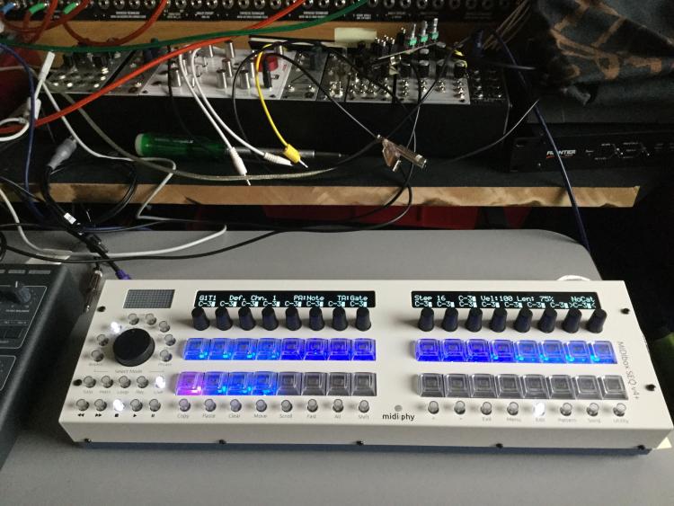
So, after perhaps an anomalous number of difficulties, my sequencer is finished. Everything went fairly smoothly after my last post, although I did manage to damage a superflux LED, probably by unsoldering and resoldering it too many times. I had some trouble getting them to lie flush with the top of the PCB and apparently one of them got heated too many times. So, again, thank you for including extra parts in the kit.
After some experimentation with a superflux LED on a breadboard, I decided to go with a blue/red color scheme. The stepping light is simply red, while the other lights are two different shades of blue to provide a little variety.
Thanks to @lp1977for suggesting that the Play button LED should be blue rather than green, if the other buttons are blue. I had already installed the green LED when I read your post, but I already had some practice replacing the LEDs in the switches so I made the change.
Thanks to @Antichambre for the beat LED diffusor idea. I liked the way it looks in your photos but I don't have a CNC machine. I made my own with a somewhat low-tech approach: I melted a little bit of thermoplastic, held a flat piece of metal against the front of the case covering the LED hole, and pressed the molten plastic against the back of the case, filling the hole. Once it cooled I had a hole filled with thin, translucent plastic, flat on the visible surface.
And, of course, big thanks to @Hawkeye @latigid on Adrian, and everyone else who contributed to this kit, and your help with my problems and questions. I've wanted to build a MIDIbox sequencer since shortly before v4 was created, but never wanted to tackle the mechanical aspects from scratch.
Now it's time to learn how to use the beast, and make some music!

-
 1
1
-
-
Number 23, I believe.
More about the build soon.
-
3
-
-
Hi Peter,
After I went to bed last night, I suddenly thought, "I bet that they put extra LEDs in the kit already, so maybe I am lucky and I already have the spare that I need." Then I was busy all day today but just now I finally had a chance to count the LEDs, and yes there are several extra white ones. There were even two extra white ones just in the bag of assorted colors.
So, thanks for your reply, and thank you for packing extras! Hopefully Mr. Murphy will be less interested in the remaining steps of building my sequencer.
--Adam
-
Hi Andy,
I finally figured out the problem, and it was not the switches. The problem was that two of the switches seemed to be sticking in the on position while I was testing them with MIOS Studio. I had tried everything else--resoldered all solder joints (twice, even), checked for shorts with a DMM, checked that the pullup resistors were connected properly, etc. Finally I had removed all of the switch caps and had unsoldered the LEDs in the two suspect switches, and I finally saw the problem while I was looking sideways at the PCB. There was some sort of fibrous material stuck to two of the pins on the resistor network. Apparently it was conductive enough to cause problems, because I removed it and the buttons then worked correctly. I don't know what it was; maybe cat fur soaked in solder flux?

Unfortunately one of the LEDs is now damaged and can't be reused. I can either order them myself or if you can spare two (if you're going to send one, you might as well send an extra) I can "buy you a beer" to cover the cost. Either is okay with me.
Thanks--
--Adam
-
Are the white LEDs used in the pushbuttons available from Mouser or Digi-Key? I'm having some intermittent problems with two buttons on my JA board. Removing and replacing them will probably destroy the LEDs, so I'm going to have to get new ones somehow.
-
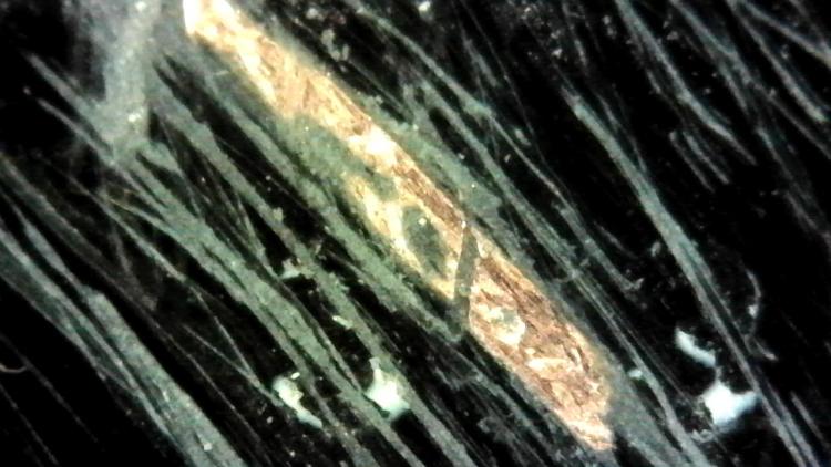
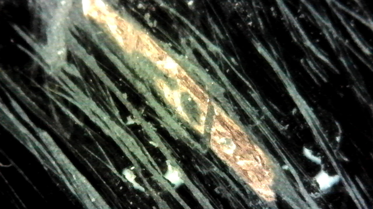
I finally found some time to work on my sequencer, and soldered the remaining superflux LEDs without trouble. I then went back to the one with the broken trace to figure out exactly where the break is. I pierced the solder mask with a DMM probe to check continuity. Once I narrowed it down I scraped away the solder mask to find the break. Somewhat surprisingly, it was broken in the middle of the trace, underneath where "SJ3" is printed. Here's a photo taken with my cheap USB microscope; you can see both what looks like a scratch at about a 45-degree angle to the trace, and more damage parallel to the trace. No, I definitely did not inflict this damage myself, and (as before) I am sure that it happened in the factory. The silkscreen was not damaged, and my DMM told me that the break was in this part of the trace before I scraped off the mask.
It's academic now but it is sort of interesting.
-
Hi Peter,
The testing is coincidental; I do not usually check every trace on a PCB...
I expect that the problem is rare. I knew from the date on the PCB that many of them must have been built by now. Your photo shows the same measurement which I made; thank you for the verification. I doubt that it is a lifted pad partly because I am using a lower temperature than usual for soldering the LEDs and I did not have any particular problem soldering that connection--and all other connections from that building session worked on the first test.
In any case, I will fix it with a jumper or with the resistor. Thank you for the offer of the replacement, but there is no need to send one. I think that I would rather fix it than solder all of those LEDs again.
-
Hi,
The PCB says "lemec v1.3_R (c) 2018". I am testing the superflux LEDs individually; there are no other components on the board yet. The cathode pins of the LEDs are not connected; I left the cathode pins pointing straight up so that I could test each superflux LED in isolation with a DMM.
Yes, the trace you marked with a "?" does not connect. There is no connection between the "1" pad for that superflux LED and the square pad marked "1" below your "?" mark.
The scratch you see is because I started to scratch away the solder mask to add a jumper wire between the middle of the trace and the pad for the LED, but then I decided to stop and document the issue before doing anything else. I think that your suggestion for adding the resistor is a better idea. It would be interesting to remove all of the solder mask to find the break, but I think that it would be more interesting to just keep building the kit.
Thanks for your help!
-
I think I've bumped into a manufacturing defect on one of my lemec PCBs. I've started soldering the superflux LEDs in groups of four and am testing them with the diode-checker function on my DMM as I go along. I have finished the first lemec PCB and there seems to be a break in one trace for the red element of one of the LEDs. The LED itself works; it lights up when I apply the probe tip to its pin directly.
By investigating other parts of the PCB I have found that each red element is connected to two of the pads labeled "1". Hence there is--or should be--continuity between pairs of these pads. In the case of one LED on the PCB, it is connected to only one of the pads. The attached photo shows the location of the bad trace; it's the third LED from the right, lower row. The green line shows the connection that works; the red line shows the connection that should work but doesn't. In other words, there is no connection between the lower "1" pad and the LED's pad.
I can fix this problem with a jumper wire but I thought I should mention it since other PCBs could have the same defect and troubleshooting the problem after the board is completely assembled could be difficult. It's possible that I broke the trace myself but I think unlikely. First, it's pretty difficult to actually break a copper trace by accident, and second I was being quite careful while doing this soldering because of the delicate nature of the superflux LEDs.
Thanks for your attention.
.thumb.jpg.aa9eb9d02784348d8aa00996eb7ebd3f.jpg)
-
10 hours ago, TK. said:
This isn't correct, see also the SN74HC595DR datasheet: http://www.ti.com/lit/ds/symlink/sn74hc595.pdf
Whoops, my mistake; you are correct. I did actually look at that data sheet, but in my haste I read the output voltage for an unloaded output.

-
Hah! Thank you for doing that test. It is good to know that I will have time to recover from my own mistakes without damaging anything. :-)
-
Thanks for your replies, guys. I'm a professional engineer so it's in my nature to first want to understand what I'm building, and second to improve it if possible. When designing hardware I try to be aware of anything which might affect the lifespan of the product. I am sure that the way you guys have the LEDs wired means that they will operate for many years--but possibly after many years these LEDs will no longer be in production and so finding replacements might not be so easy. Nobody knows. Hence I might feel better if I use 100R resistors. Of course the same is true for the mechanical components, which is exactly why you chose the good encoders and tactile switches. Nobody can make hardware that lasts forever, but we can do our best to make it last a long time. I started building my modular synthesizer 13 years ago and I have other synthesizers which are around twice that old. I plan to keep using them for decades.
You guys have a good week, too! Hopefully I will have some time for more soldering. :-)
-
24 minutes ago, latigid on said:
If you're concerned with the LED lifetime then simply increase the values of the RJ resistors to a current you are comfortable with.
Yes, that is my plan. I started thinking about all of this because I'm considering a custom color scheme using a single element for the "A" light and two elements for the "B" light.
25 minutes ago, latigid on said:I would consider the probability of an LED matrix "freezing" in the way you describe as a low risk though.
Definitely, except that there is a good chance that I will someday make my own modifications to the firmware... :-)
Thanks for your help!
-
10 hours ago, latigid on said:
So, rant over! :-) If that wasn't your intention, then I'm sorry.
It wasn't my intention, no, although this is the first time I've heard of this procedure for asking for the schematics in response to an order confirmation, so I will do so.
My concern about the current is partly this: if the software fails for some reason and the multiplexing stops, it is possible that the LEDs receive the full current for some period of time until the power is shut off. Under that circumstance, I'm not sure that relying upon the 100mA current per chip is safe if the individual elements have a lower rating.
I'm not concerned about burn-in testing showing whether or not an LED operates in a short-term test. I am concerned about the operational lifespan of the LEDs being affected by the current they are carrying, particularly since they're being operated above their stated limits.
-
I'm about to start soldering the Super Flux LEDs. I'm curious about the circuit driving the LEDs, specifically the supply voltage. I found what I think is the correct data sheet for the LEDs here:
https://files.elv.com/Assets/Produkte/10/1094/109464/Downloads/109464_superflux_data.pdf
According to this sheet, the typical forward voltage of the green and blue elements is 3.4V, so the supply voltage on this PCB is probably 5V (since 3.3V wouldn't be enough). On the other hand, the red element has a forward voltage of 2.0V. If the LEDs were driven directly by the 74HC595 shift register, whose outputs are very close to the supply voltage, then the current through the LED would be (5 - 2)V / 47ohms = 63.8mA. This is higher than the 50mA maximum current stated on the data sheet for the red LED, and much higher than the 20mA typical current used for most of the LED's specifications. The same is true of the current through the green and blue LEDs, although the difference is not as dramatic: 34mA calculated current vs. the 30mA maximum stated on the sheet.
So, I assume that the LEDs are multiplexed, at the very least, but even so the amount that the red LED's current exceeds the stated maximum is somewhat disconcerting. So maybe the operating voltage is lower than the 5V expected output from the shift register? Is there another voltage drop somewhere?
Thank you for any comments. Of course all of these questions would be answered for me if the schematics were supplied with the kit.

.jpg.24462120e231e3a38c8d0a553aead459.jpg)
midiphy SEQ v4+
in MIDIbox SEQ
Posted
Thanks for the explanation. The challenge that those of us with little or no prior experience with MIDIbox in general and the sequencers in particular is that we're often left puzzled by certain operational details, such as this one. As far as I can tell, the only documentation for this feature is "FAST - Use this button to speed up the encoder and datawheel increments/decrements." That doesn't tell me that I also have to rotate the encoder quickly. All other devices I've used work one way or the other: either there's built-in acceleration so rotating the knob faster increases the value change per click, or there's some sort of switched behavior (like pressing the encoder) which changes the value change per click. Hence I didn't expect the v4+ to require both gestures to change its behavior. Anyway, at least now I know what to expect.
Encoder acceleration is a tricky thing to implement well. I've tried a couple of different approaches in my own projects and to get it to work really well usually involves scaling the acceleration based on the range of the target parameter. Of course this means designing and implementing a parameter-management system, too...
Thanks--
--Adam