

Antichambre
-
Posts
1,291 -
Joined
-
Last visited
-
Days Won
101
Content Type
Profiles
Forums
Blogs
Gallery
Image Comments posted by Antichambre
-
-
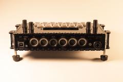
No space to put the screw inside? Or this is a choice?
18 hours ago, Hawkeye said:But the rubber feet (Reichelt GF 2) will really hold it in place on various synths
I Like this.
Because screws are outside, are the small vertical plastic pieces enough? are you not afraid about gap in the middle of front and bottom acrylic panels(plastic bend)?
Bruno -
19 minutes ago, latigid on said:
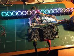
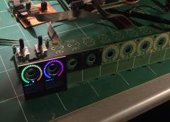
Epic! Must be quite zen soldering all of those LEDs...!
I still do a magnesium cure a few days before

With the right method it's about 6 hours to solder and test those 512 rgb leds... -
Just now, ilmenator said:
Interesting topic! Though it's a little bit difficult to follow the discussions taking place as comments in the image section of the forum. Why don't you just create a thread describing the project and put/link your images there?
Don't worry, I will do it. For you to know that the dokuwiki already exists even if I have to update it also.
-
Thank you!

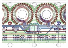
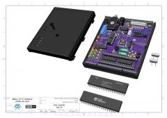
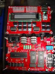
Some explanation:
Here I test the Logic Clocking/Addressing for 32*16 multiplexing around the TLC5958. With all the leds this time.
Previously I first tried to code this multiplexing circuit directly with the STM32F4 but it was too much process for a very bad result.
Then I designed an external logic circuit for that purpose, it was working but a was very complex circuit.
And finally I reduce this big logic circuit to one unique programmable logic ic, the Lattice CPLD.
Here I used an LC4256V evaluation board from Lattice. It's a TQFP100 with 256 macrocells and this is too much for that purpose.
So I make the VHDL program very small to fit in a LV4064(64 macrocells) which exists in a small TQFP44 package.
The components on the breadboard are just for 3.3V to 5V level shifting.
Voilà! -
Hi Datacore,
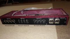
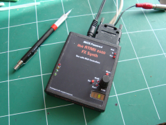
It's Neutrik SerieD USB NAUSB-X
BR -
Yep! you remove the plastic after solder, of course.
-
Yes picture upload problem, sorry for that.
no way to delete It too, no option except "édit details" in manage picture button.
Seems I'm not the only one:
-
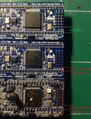
Will be difficult because, headers on the core are too high no enough space to bend the pins.
You can solder wires(I keep cutted resistor legs for that) on the pins which are used in your app. Think about the bootstrap pin too.
But it's not a good solution, for the raison you can imagine.
Fortunately Lextronic always have a stock of rev B.
-
1 hour ago, Phatline said:


Don't be afraid you will love it ;)
I would like to show more about, but I've got strange behavior with pictures, for example this one uploaded in a wrong album...
-
Yes no 3d, no fake lol
It was not easy. The difficulty was to route the rings. it's 16 rgb leds with 32:1 multiplexing, 2 mux adress by ring.then it's a 48 channels bus which passes thru the rings on full length of the board. This top board is 4 layers but even with that, it was hard work. -
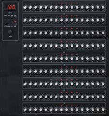
The MAQ 16/9 ? ;)
-
Hihi :)
Thank you my friend!!! -
Thank you :)
It's AutoCAD ! -
Hi Peter,
My first intention was to implement a "mini CS" to change patch, bank...But i think it's not necessary, I only use the MasMsp Manager. But I let encoder and 4Digit on definitive PCB, (yet designed), we are not obliged to put and use it and it's difficult to cut squared hole in cartridge.
Maybe one day firmware will be an MB-link one!
You asked me for demo sound, you can find it on the blog!!!
-
Rendez-vous at kaffe Machine! Great ... in french : C'est bon ça!!!
-
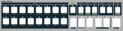
This is just an eps file at this time.
With SidMonster, we are working on it.
With printing/cutting machine and metallic inks on adhesive.
gonna make a test and show result...
"illskins" coming soon...
-
so do i get that right, it has still the kpr sound in it?
awesome work!
Thank you
And YES! It was the goal.
Some video? ;)
It was not so difficult, Digital and Analog are clearly separated.
-
Thank you guys!
There's some analogic mods to do with KPR.
ex: Bass Drum Mod.
Maybe it can be controlled by midi?
But for the moment, i don't reopen it, i play it!
-
Oh and...
Connection! 14 pins cause no led, only 5V supply 150mA typ. 220mA max. (no pots).
-
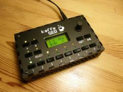
Hi,
Yes i have modified the LCD driver.
Id=7 "custom LCD", only for adjust contrast @ startup.
It's a Samsung VFD, 4/8bits connection, model 20T202DA1E.
ith all features needed.The only difference is that contrast is digitally controlled.
Find on net @24€.
For the color filter, I used "Lee Filters", after a little test with sampler.
I' ve finally choose number 085 "Deeper Blue":
You can find if in professional audiovisual shop.
Or for a little stamp i can send it, a letter format is enough, and i bought 1 meter...
`
Regards.
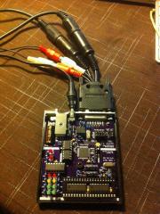
Standalone_TPD.jpeg
in Finished MIDIboxes
8Posted
Mignon!