Fairlightiii
-
Posts
234 -
Joined
-
Last visited
-
Days Won
5
Content Type
Profiles
Forums
Blogs
Gallery
Everything posted by Fairlightiii
-
DINX4 & DOUTX4 schematic verification
Fairlightiii replied to Fairlightiii's topic in Design Concepts
Ok. I've redesigned the board. This is the modifications: >All the components (with its silkscreen) except encoders and LEDs are placed on the backside of the board. >I modified placement of encoders: each encoder is assigned to the good LEDring: We will normaly no longer need to modify the assignation of encoders in "MIOS_ENC_PIN_TABLE". >I corrected the wiring of LEDrings because of the different order of pining between logical symbol of Eagle and pin configuration of the SR: We will normaly no longer need to modify the LEDring pattern. Sorry ilmenator and Peter: no DIL header and no pushbutton (very few free space). I propose to submit the board to Tim/SmashTV and if he is ok to sell this board in his shop and make a limited bulk order for (at least) non US people. Please give me your feedback. Best regards, jerome. NorthernLightX: I believe you :thumbsup: MBHP_DINx4_DOUTx4_Rev2.pdf MBHP_DINx4_DOUTx4_Rev2_Shematic.pdf -
DINX4 & DOUTX4 schematic verification
Fairlightiii replied to Fairlightiii's topic in Design Concepts
Thank you Peter and others for your support. Don't you think that the no-corresponding LEDring/Encoder would be enough crucial problem for users? No problem, it was in my mind. PS: For every reader, sorry for my poor english! -
DINX4 & DOUTX4 schematic verification
Fairlightiii replied to Fairlightiii's topic in Design Concepts
I've asked to my PCB manufacturer and the price should be around 11-14 euros each (+shipping from me to you) depending the number of people interested. Maybe it should be interesting to add also difficult/expensive sourcing parts as DIL resistors networks or encoders. I'll take time to manage a bulk order as soon as possible. If somebody else is interested by this board he should make himself be known. -
DINX4 & DOUTX4 schematic verification
Fairlightiii replied to Fairlightiii's topic in Design Concepts
I have effectively to place a new order for this PCB because I needed 3 boards but I've destroyed one during "barbarian" desoldering session. I'm thinking to propose an bulk order or at least a limited batch order (not much spare time actualy). -
DINX4 & DOUTX4 schematic verification
Fairlightiii replied to Fairlightiii's topic in Design Concepts
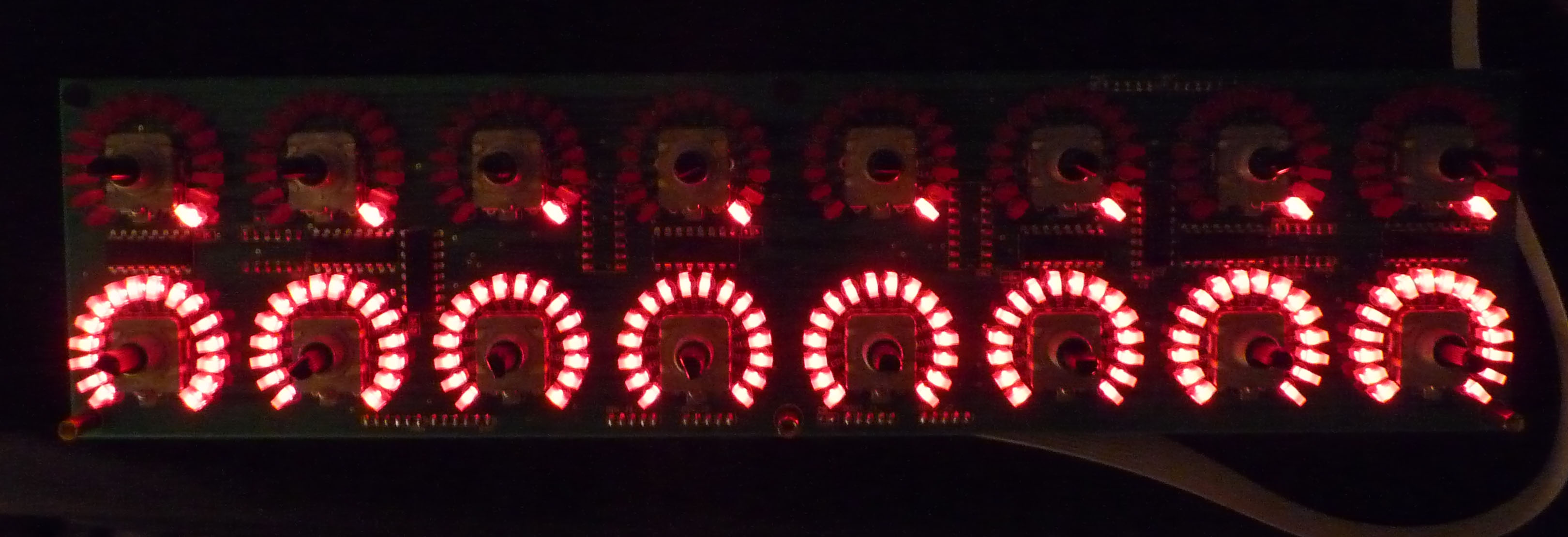
ok. The PCB is ok with minor modifications of the configuration files: >I've made a little mistake during the design of the PCB: I have started to increment the encoders from left to right and the LEDrings from top to bottom: each LEDring initialy didn't move corresponding the good encoder. In the file "setup_midibox64e.asm": >I have also modified the LEDring pattern because the first LED which lighted up was the middle one (and I don't know why because the schema seems ok). In the file "mb64e_presets.inc": Jerome.
-
Hi Julien. You probably already know this links: http://www.polynominal.com/site/studio/gear/synth/roland_d550/lcd.htm http://www.backlight4you.com/product_info.php/info/p926_EL-Panel--blue-green--21mm-x-166mm--laminated.html The second is for use with a non backlighted LCD wich seems to be more common in this thickness. Regards.
-
Smashtv Core, LTC and DIN module dimensions
Fairlightiii replied to Fairlightiii's topic in Parts Questions
Hi Rosh. I would'nt bet on that. I've found more or less between the holes with my rule: Core8 r4: 7.2mm and 5.4mm. LTC r2: 5.55mm and 4.05mm. ...It's not easy with populated modules. As holes seem to be 4mm and I will use M3 screw, it should be ok with my "eyes precision". -
Smashtv Core, LTC and DIN module dimensions
Fairlightiii replied to Fairlightiii's topic in Parts Questions
Some answers in 2005 (no information about drill holes): -
Hi everybody. Is there someone which know the exact dimension between the drill holes of SmashTV core R4, LTC and DIN modules? The layouts are differents than the *.brd of TK. I could take a rule and do it myself but the result won't be so precise than the *.brd itself. I sent an email to Tim but he must be busy now. Thank you.
-
Thanks jojjelito. It's exact, I didn't realize that before (certainly because I planed to use PE-BK/WHT caps during the casing of my Shruthi)! Regards.
-
Hi everybody. First I would like to ask to people that have already experienced the famous couple TL1100F160Q (switch) / C&K PE BK (cap switch) what should be the better aperture size for 3mm acrylic panel with a standard spacer of 10mm? I found differents sizes for differents projects (sammichSID, x0xb0x, Shruthi, ...). Second question: Did anybody used the medium grey acrylic panel of Formulor.de with (red) LED regarding the tranparency? Thank you. Best regards.
-
DINX4 & DOUTX4 schematic verification
Fairlightiii replied to Fairlightiii's topic in Design Concepts
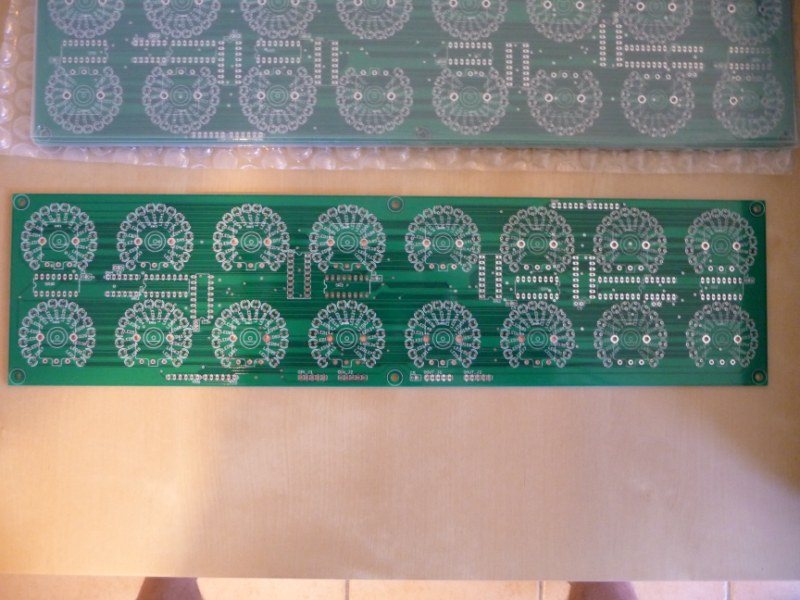
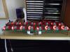
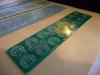
...back side and two little sisters.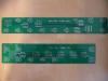

-
DINX4 & DOUTX4 schematic verification
Fairlightiii replied to Fairlightiii's topic in Design Concepts
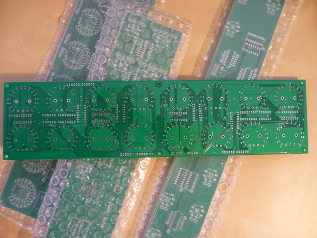
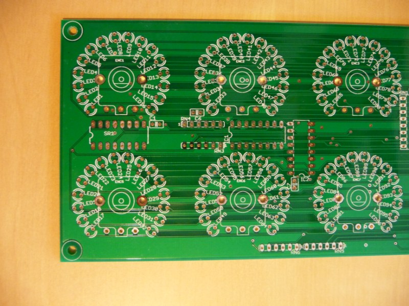
...All seems ok except the layer 121 (_tsilk) which is not silkscreened! -
DINX4 & DOUTX4 schematic verification
Fairlightiii replied to Fairlightiii's topic in Design Concepts
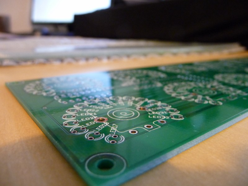
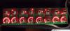
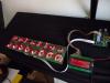
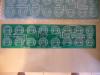
My first PCB arrive today. This is some pictures. And yes the pads on the bottom seem to be the same than the top side, so I could solder all except serials registers (polarized) on the bottom side. I have now to test them...

-
DINX4 & DOUTX4 schematic verification
Fairlightiii replied to Fairlightiii's topic in Design Concepts
Yes I know, but for my project I will need full DIN/DOUT populated. When I will have extra time, I can create 4x2 module (it seems not easy to make 4x1 or 8x1 without letting too much space between LEDrings) making variation of my initial file. It's a good idea, I will try to do it as soon as possible (but I don't think I can leave so much space around). No. I've dealed with this problem during design but I wasn't sure I could put components on the bottom layer just using Eagle "Mirror" device (what about silkscreen, ...? ...Say me if I can do it just like this). Anyway ICs, RNs and Caps shouldn't be a problem regarding height of LEDs for example (I planed to use 2x5x7mm rectangular LEDs). Pin headers could be. -
DINX4 & DOUTX4 schematic verification
Fairlightiii replied to Fairlightiii's topic in Design Concepts
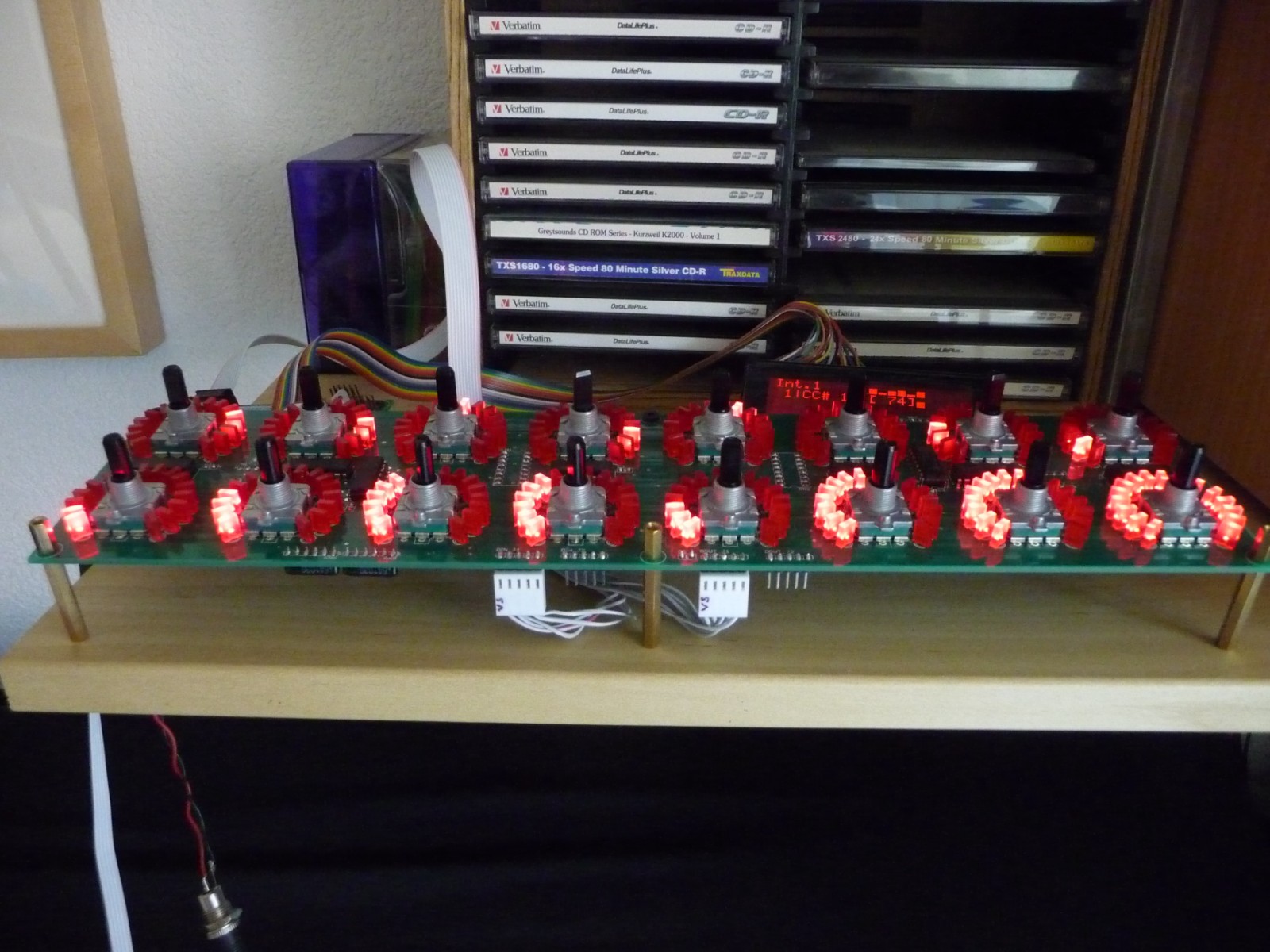
For information the board is 3,368 x 13,472 inch (in cm: 8,55 x 34,22): just less than 2U. The diameter of each LEDring is 1,378 inch (35 mm) with 5mm LED, 1.299 inch (33 mm) with 3mm LED. We can use round or rectangular LED because of the different angle of each one of the ring. The space (horizontal and vertical) between each LEDring is 0,306 inch (7,772 mm) in case of 5mm LED. -
DINX4 & DOUTX4 schematic verification
Fairlightiii replied to Fairlightiii's topic in Design Concepts
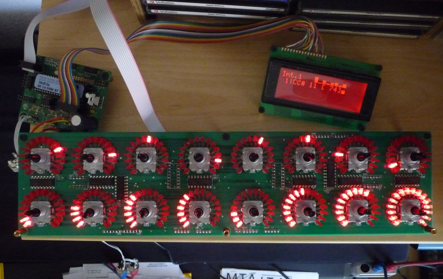
Thank you Peter. Exactly. ...If it all works out. I have resolve all the problems but: >I've spent so much time on this that my eyes can't be sure of the schematic (I would prefer "more fresh people" check it again)! >Eagle say me that I have several "Zero length airwires" (yellow X-shaped cross) I still don't know how I can handle them (and if it is crucial for the building of the board). I think so! -
DINX4 & DOUTX4 schematic verification
Fairlightiii replied to Fairlightiii's topic in Design Concepts
I've checked the schematic and found some (big) mistakes. I've corrected them and give the board I made with. Schematic_MBHP_DINx4_DOUTx4.pdf MBHP_DINx4_DOUTx4.pdf -
DINX4 & DOUTX4 schematic verification
Fairlightiii replied to Fairlightiii's topic in Design Concepts
Thank you. You save my life. I modified the shematic according your advice. About the 100uF cap, I found an answer in If you have checked this schematic and no found error, don't be shame to say just "ok". Thank. 16Ledring&16Encoder_v5.pdf -
Hi. I have done a schematic using Eagle with a DINX4 and a DOUTX4 populated by 16 ledrings and 16 encoders. As it was my first shematic and before going more far, I would like to know if there is any error. Second question: What about the 100uF cap between VCC and GND near the first pinheader (J1) into the DOUT (I have seen some schematics with and others without)? Suggestions are welcome. Thank you. Jerome. DINX4&DOUTX4.pdf
-
Thank you for the trick Julien but I've already bought all the components and tools and there are not CMS compliant. Making the PCB will be a long long step (I've only "played" with Eagle 1 or 2 times). Am I too ambitious to thinking all the components will go on only one PCB? I joint for those who are interested the last version (I'm pretty sure) of my frontpanel. Regards. Jérôme. V5.1 A4.pdf
-
There's several years I knew the project midibox of Thorsten and thinked about create my own midi control surface but the fact I was newbie was an obstacle. One day I say myself: go! So I've bought all I need to build my project (soldering iron, multimeter, SmashTV's PCB, encoders...). Of course! I plan to integrate all the composants in the top of the PCB. Is-it possible(I should have a space of 9,3 mm between the pannel and the PCB)? I don't need so much space! I have modified my frontpanel to comply 5U. This project includes: 49 encoders, 30 buttons, 2 rotary switchs (AIN module with differents resistors), 39 LEDrings (bargraph of 10 LEDs) and 48 LEDs. All the parameters of the Maad's firmware will be directly accessible. I have completed by 7 extra encoders and 6 buttons (4X DINX4 module full). Regards. Jérôme. FPD V4 5U A4.pdf
-
Thank you Julien. I'll spent times to study your project ASAP. I've already bought and built SmashTV's core, DIN and DOUT. Some months ago I've made some tests trying to make a control surface but unsuccessful with LED feedback (but I've no spent enought time to debug). I must take time and restart little by little from the begining . Now I have to modify my frontpanel because I must comply with the 1000dm3 restrictions of goldphoenix's for the PCB, passing the frontpanel from 6U to 5U and resolve this problem of only 2 extra LED outputs I have to find (removing 2 LEDrings maybe?). Regards, Jérôme. PS: If someone has this synth, could he PM me (I have 2 or 3 questions about it). Thanks.
-
Merci Julien. (je continue en français) It seems easy when you read it like this...but it's not impossible that I come back to you for more advices in the future. Do you think I should begin now to build my PCB (eagles), it will easiest to test the code with? Regards.
-
I've already discovered this beautiful project from jackchaos. The two synths share the same Curtis chip CEM3396. I own two MS6 but neither of them works (lacking baterry and PSU problem). I brought them -a long time ago- to a friend which was suposed to repair them (I am newbie concerning electronic/electricity). Yes it is CC instead Sysex so I think it will be easier (no buffer …). My programming problem is that I've to know how modify the state of the LED when I push a button (first push: first LED lit (others LEDs turned off) and CC parameter X sent, second push: second LED lit (others LEDs turned off) and CC parameter Y sent, ...). Thank you Julien for your interest. Regards.