

Hawkeye
-
Posts
3,632 -
Joined
-
Last visited
-
Days Won
36
Content Type
Profiles
Forums
Blogs
Gallery
Posts posted by Hawkeye
-
-
Restarted the mailserver, sorry for the inconvenience, it appears to crash every few months...
Many greets, Peter
-
just a very short note - if you want to create an oscilloscope output (i.e a waveform display) with many set (and cleared) pixels per frame, it might make sense to just send a whole framebuffer update for every frame (buffer pixels in ram, then send full screen) instead of individual pixels - you can have a look at playground/hawkeye/mbprogramma to see how it works there (implemented a .pcx bitmap loader for label OLEDs) - it is quite simple and should be fast enough if you only want to update a single display. But you need to manipulate single pixel data in a way Bruno wrote, i.e. with bitwise or, and, xor operators because of the packed memory format... The advantage of this is, that a screen only takes (128*64)/8 bytes of ram.
Have fun and good luck!
Peter -
very cool! :)
@norbim1 yes, it is based on the new waveshare core, but Andy created a completely new carrier core board for it, especially for the LoopA form factor, including onboard 4x MIDI OUT (OUT4 doubling up as a future BLM extension connector :)) and 2X MIDI IN for your favourite keyboard and sync downlink from a MBSEQ :)...
As of today, the sources compatible with the new PCBs/UI are also checked in to the MIDIbox mios32 subversion repository, so if you want to test-compile it, you can check it out @ trunk/apps/sequencers/LoopA :)
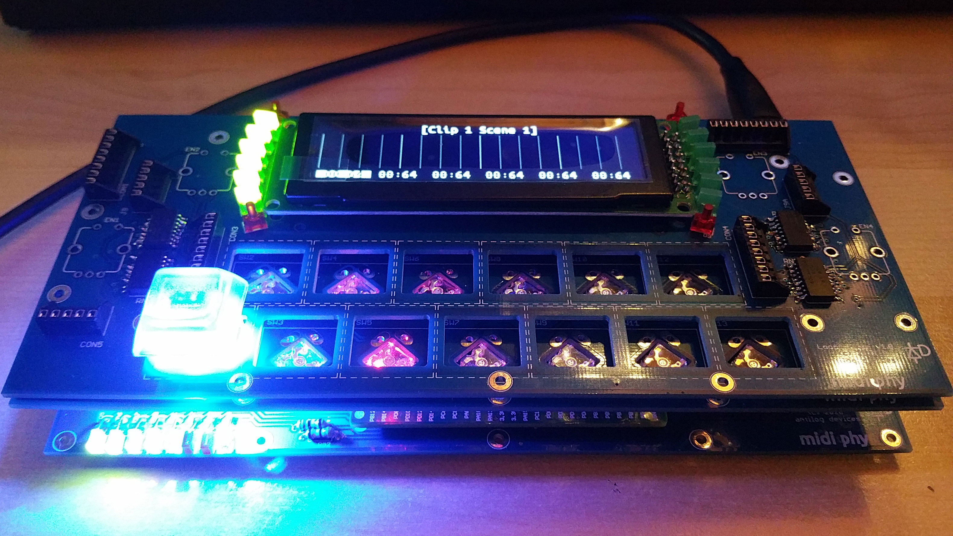
The code and functionality will be extended after availability, but it works already with support for six "scenes" with each six polynote "clips", that can be dynamically requantized while it is running - the display also shifts the notes around graphically, so you see what is happening - hoping to be able to do a demo video of the new version soon!
Many greets,
Peter -
Nice one! :-)
-
Ongoing BOM validation - looking good! The picture of my test build below is still missing the encoders and a few more Matias switches/keycaps.
Fantastic job, Andy! The small form factor in conjunction with the superflux RGB LEDs and Matias switches with additional encoders definitely makes all the difference to my first hacked perfboard build.It was not too demanding to build (can be done in an evening if you push it), but it has a high packaging density for a DIY project and it requires a bit of patience with board interconnections (three boards in total). That does not classify it as a beginner project - but hey, as you can buy everything else, a challenge from time to time is exactly the right thing! :)
We will document it properly, so that everyone confident with wide-pitch SMT soldering (1206) can build it, too! Availability target:late springtime, make that midsummer, the SEQv4+ has priority.Many greets, Peter

-
@Elektruck yes, with a FAT32 formatted SD-card you should be fine, there should be no root directory file limits using that filesystem, only the older FAT12/FAT16 filesystems impose such a limit.
Many greets, Peter
-
Hi,
it might be outdated information, but back from old DOS days i remember there was a limit of how many files might be allowed in the root directory of a FAT filesystem - and it was around the 8-bit barrier, if i remember correctly :).
This limit did not apply to subdirectories - so the underlying filesystem might be the reason? There might be differences between FAT16 and FAT32 - and TK's recommendation should always work - use subdirectories! :)Many greets,
Peter -
Hi,
maybe you could also be interested in using a MIDI looper with primarily haptic interaction. This approach would allow you to make loop-based music completely without a display.
Andy and I are currently developing such a looper, based on TK.'s MBSEQ sequencer engine. It has a display, but it might be reconfigured to offer these primarily haptic functions:* turn an encoder to change the currently active track (on which you are recording)
* use an encoder to change the pattern length of the currently active track (from a limited number of presets)
* use a footswitch to start/stop playback and recording
* use a footswitch to "punch out" notes during rerecording of a loop
* use a switch (can be marked with "braille" markings) to clear currently active track
-> this would allow for a basic, purely haptic recording setup* use switches (can be marked with "braille" markings) to choose currently muted/unmuted tracks
* use an encoder to change the current scene (multiple clips are played in parallel tracks in a scene, switching the scene will "load" new clips into the tracks. A track is associated with a MIDI instrument)
* use an encoder to change BPM
-> this would allow for live sequencing, also without a displaySuch a setup might be used to drive several MIDI hardware synths using a MIDI keyboard.
Many greetings,
Peter -
@WingMaPlease stop flooding the forums - you can find everything documented well, as all the others told you already. And yes, it always makes sense to use the current core and not an old one, so STM32F4 is the way to go...
-
Awesome, and i mean REALLY awesome PCBs, man! Thanks! :)

PS: as you can see on the second photo, there is an URL (nothing to be seen behind it yet!) - with TK.'s permission and also with very friendly coordination and cooperation from John/modularaddict.com, we will be opening a little eurozone based MIDIbox store at some point in time, where you can get these goodies, including the new MBSEQv4+ boards :). US-based customers can (at a little later time) obtain the PCBs from John's shop.
Many greets,
Peter -
Hi Shuriken,
uh-oh, hopefully the move is not too stressful!
I might be interested in the TM3030 - does it work and do you have some some transistors and the schems (came with the purchase of the board) for it?
If that is a given, i'll gladly take it - just don't have the time to commit to any builds at the moment, but would enjoy a midi controlled 303-clone :).Thanks and many greets,
Peter -
Can you check the 5V rail, when you power it externally?
100mA is a too low current - a reason might simply be, that the PSU is damaged and not capable of delivering 2 Amps.
That could cause a voltage drop to probably way below 4.5V and a low current reading.
It is strange, that it does not work with an alternative external power source, though, but please measure the 5V rail voltage and report back.
Many greets,
Peter -
Welcome to MIDIbox! :-)
A quick way surely would be to build or buy an oldschool PC and install some DOS software on it. Some musicians are pushing the OPL3 to its limits using that setup, e.g. "Diode Milliampere":
To simplify things, and have a portable music player, you could just buy e.g. an old Toshiba Libretto laptop :-).
But, as you are an electrical engineering student and on MIDIbox, this would be our preferred project:
http://ucapps.de/midibox_fm.html
It is well documented, but you need a bipolar power supply and some time. If you build one, you will have better MIDI connectivity and "playability" than from a DOS machine.
Good luck and have fun!
Many greets, Peter -
Here is a walkthrough on the ELO boards by Andy:
https://www.youtube.com/watch?v=iKZ_7VVqbFo
The LEDs are RGB with an integrated controller (WS2812), fully mixable by MBNG, you can achieve many different colors.
Many greets,
Peter -
well, that is most likely a problem with the forum software, which we did not write - it also gave us the headaches about the vanished old gallery pictures... The problem you describe might be possibly fixed (no guarantee!), when the forum software is updated to a new version at some point in time - there are plans to do this, also you can accelerate the process by sending hosting donations to TK., e.g. via PayPal, any amount will help, thanks! :-)
Many greets, Peter
-
4-wire spi:
http://ucapps.de/mbhp/mbhp_lcd_ssd1306_multiple_mios32.pdf
needs said 7 pins to connect - in the ebay listing there are pictures with 7 pins and what looks like spi pinout, it might work - i'd recommend to order one or two displays to test first, before buying a whole batch - looks like a fantastic price, btw! :-)
Many greets,
Peter -
yes, you need the additional pins - 4 wire spi connection method, methinks i needed to attach 7 wires to each OLED, beware of cable spaghetti! :)
Andy might have some boards, that we wanted to use for MBProgramma V2, but there might be yet another iteration... These would mount the OLEDs in diagonal shape and there would also be room for the encoders.
But i can understand, if you want to reuse the MBLRE boards you have, it is just a helluvalot to wire, but it will work in the end, i am still using the old Programma prototype very often!Many greets,
Peter -
That's really awesome and helpful during development, great job, Bruno! :)
-
-
Well done - link to the original/first post added. Thanks for searching! :)
Many greets, Peter -
Hi and welcome to MIDIbox, great that you are building again! :)
The BOM may use other LEDs than i used in the old tutorial and therefore it may reference different resistors for these different LEDs, which may explain also the 1k resistor.
But: normally no damage will occur (for normal LEDs and normal resistors > say 100 ohms), only the brightness will vary.
So: you could easily exchange the 220ohm for 470ohm resistors you have on hand, the corresponding LEDs will just not be as bright as the others.Trick: if you have more 470 ohm resistors, you can "parallel them" to get effective 235 ohm resistors, which is close enough to the 220 ohms that you won't see an optical difference - you can even "piggyback" them later on, by just soldering another 470 on top of an existing one :)
Many greets and have fun building!
Peter -
I don't know if we should upload software made by others on here (even if it is free), but you can always try the wayback machine:
web.archive.org
Then enter ctrlr.org as URL
Then click on the circa date the files should have been present in their download area
Then click on the download area - i just did this experimentally for 2013 and it works - but you have to search for your exact release by properly travelling in time, which is half of the fun :)
http://web.archive.org/web/20131125171837/http://ctrlr.org:80/nightly/
Many greets and good luck!
Peter -
Hi Bruno,
Hm, as the four "control" output ports only have 2 pins and as it is called "midibox", they will most likely carry the unmodified MIDI signal, only two pins are needed for that (ground/signal).
I agree, that they probably have an optocoupler and maybe some buffering/inversion (e.g. with a hex inverter like for a standard midi thru box) in there.
But as long, as you do not know the exact protocol between the control box and the pedals, there could be also some other kind of stuff going on... if you assume plain midi (as do i), you could try to control one of your empress pedals with an experimental midi breakout cable, one end a 1/4 inch plug, the other end connected to MIDI GND and MIDI data and see if that works.
The more "safe" variant would be to open up a pedal and see, if it looks like a MIDI-IN circuit wired to the "guitar cable" port, i.e. if there is an optocoupler and a resistor connected, if so, you should be able to try sending MIDI without a danger to the fx box.If that works, you can just build a basic MIDI thru box instead of buying this so-called "midibox" :-) Good luck! :)
Many greets and have a nice weekend!
Peter -
No problem,
here:
http://www.midibox.org/dokuwiki/doku.php?id=wilba_mb_6582
especially here for the baseboard:
http://www.midibox.org/dokuwiki/doku.php?id=wilba_mb_6582_base_pcb_construction_guide
and maybe this one for the control surface :)
Have fun!
Peter
Microwaved
in Songs & Sounds
Posted
Hey,
it has been a while, this song sat on the sequencer for too long and had to be finalized one way or another :).
Only using the LoopA (i have to get back to MBSEQ goodness soon :) and six MIDI loops in two scenes, hope you like it :)
The next videos uploaded will be build videos for the new SEQv4+ and the LoopA, so you will be spared from new songs from me for a while :)
Thanks for watching and listening and enjoy the weekend!
Many greets, Peter