

Hawkeye
-
Posts
3,630 -
Joined
-
Last visited
-
Days Won
36
Content Type
Profiles
Forums
Blogs
Gallery
Posts posted by Hawkeye
-
-
@jingo thanks for your interest, there are qualified builders around, maybe someone will contact you. We will have to get shipping of all parts including the case going first.
But here is the good news: Adrian shipped the final/release version of the lefthand jog/JA case with printed labels to Germany, so we'd expect to be able to provide you with new images of the final unit next week. So we can compare if it came out like the label photoshop mockup provided earlier :).
The next phase is a final "fit-test", to see if everything can be installed nicely, then Adrian can ramp up the production. If all looks good (which is expcted), the v4+ could be under your Xmas trees, we should be able to ship everything essential for the v4+ in November.
Many greets,
Peter -
Looking good! :)
-
Hi and welcome!
If you require normal audio output (not mp3, which is a digitally encoded format) in conjunction with synchronized MIDI note output, any DAW should be able to do it. The VSTs/VSTis would convert internal MIDI to audio ("through jack") and you could also have a plain "MIDI track" outputting the associated MIDI notes to any USB MIDI interface.
What will also work in the MIDIbox context is to use a MIDIbox sequencer, output MIDI notes to any MIDI OUT, attach a synthesizer to that port via MIDI, grab its audio from its audio output port and the associated MIDI data from its MIDI THRU port.
Have fun and many greets!
Peter -
Hi Roel,
congrats to the build, thanks for the confirmation that it mostly worked out without a problem and glad that you like the docu, can't wait to get working on the second part! :). If there is similar feedback from other builders regarding the cheaper 6N138 sockets, we will replace them in the BOM. Personally, I've not yet had problems with them, but you are right, you need to make very sure, that the IC legs are properly bent for them to fit nicely.
Regarding the SD-card, can you try to format externally using your computer using FAT32 as a filesystem? If the micromatch connection is ok, you should then be able to use it in the SEQ. (You could use the MIOS studio filebrowser to verify it works and try to store files on the formatted card via MIOS Studio filebrowser).
You can also partially test some of the PCBs that you built using MIOS studio, e.g. if you enter "play" (or "start", can't remember right now :)) at the console prompt, a backside LED should flash (like in the video right at the beginning when the unit backside is shown), the other backside status LEDs are yet unused - the v4+ software would need to be extended a bit to make proper use of them (should not be terribly difficult, i think we could indicate "BLM connected", "Gate" and "MIDI in" activity with the remaining three LEDs). Also, when the sequencer is playing, the first track imho is filled with some notes per default, so if you attach a synthesizer to OUT1, you should be able to confirm that the first port on your MIDI8 PCB works properly.
There is no ethernet extension planned (or room for it in the case) - effectively "on board ethernet" was dropped after the LPC17 core generation and the introduction of the new STM32F4 cores. But i am sure, if there was enough demand, with a bit of tinkering, it should be possible to design an "out-of-the-box" solution, that might connect e.g. to the BLM port (also carrying power) or two classic MIDI ports (external power required then), which could provide ethernet forwarding. Until a solution like that is implemented, it should be possible to forward/route a MIDI pair to your old sequencer and use that as an ethernet bridge (even if it does nothing else and just sits in the corner :)).
Have a great day and many greets,
Peter -
Nah, it's not enlightened, i mean the LEDs hopefully are, but us... not yet :)
The RES-SD BOM resistor values (1k) came from the original wiki RES-SD docu and seemed to work out for my initial RES-SD tests with these LEDs. No big care was taken for total brightness equalization, just a look if moderate-brightness indication works properly. So, if there are updates to these resistor values, please shoot :).
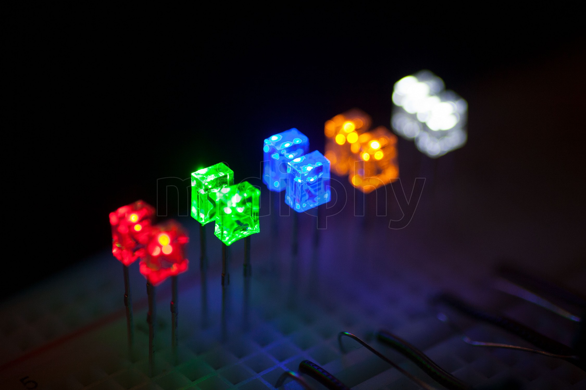
The resistor values listed in the shop for a 5V source were more or less trimmed by experimentation to achieve similar brightness for all multi colored LEDs, and primarily done to be able to take a good photo. As in this scenario the LEDs are a bit brighter and are driven "hotter" than for the RES-SD case, i also measured the LED currents to make sure, that no LED exceeded a two digit milliampare value. The recommendation should be far away from limits (being at 20mA or such).
But, as the brightness curve of these LEDs is really highly nonlinear and the LEDs begin to light up at very low currents already, probably using the same resistors everywhere will not result in a totally different picture than seen in L-X-01 for example in the shop:
In the end, and as Andy said, you've just got to test and fine-tune to your preferences! :)
Many greets,
Peter
-
Fully agreed, brightness perception is highly subjective!
The 5V values were deduced on breadboard with a DMM measuring current @5V. The 3.3V values above were just calculated with an online tool from the 5V values and are not tested at all.
Regarding SD-RES: the LEDs are efficient enough to light up as signalling LEDs with 1K resistors - we don't want to illuminate the room from the back of the SEQ :).
Also, the "brightness curve" is highly non-linear. I.e. a such a 4x3x2mm green LED will surely light up already fairly brightly at 1mA, and will by far not be 10x "dimmer" than at 10mA.
Many greets,
Peter -
Hi Bruno,
Thanks for considering to use them, just plugged the 5V data in a LED resistor calculator, derived the "diode threshold voltages" and calculated a bit. While i can't live-test at the moment i'd recommend to test with these values:
(Edited)
120R@3.3V for blue
150R@3.3V for white and green
180R@3.3V for orange
220R@3.3V for redThe LEDs are efficient, most are relatively bright already at 2mA, will saturate in brightness somewhere below 10mA, you can definitely test with a variety of resistors for your desired target brightness.
Many greets,
Peter -
Thanks jaytee! :) You still have a beer on my tab, say a word, whenever you are near Munich!

Many greets, Peter
-
@rbv2 if you have a lot of synths hooked up to multiple sequencers (hardware or DAW), as mentioned above, the best way to do it would be to use one big MIDI router to connect everything to :).
Another not-so-bad idea is to use MIDI-THRUs directly on your v4(+) to multiply each of your OUT ports with only a single "hex inverter". That method is cheap, and adds only minimal and uniform latency. If you use the eight output ports of the SEQ and multiply them with eight quad MIDI thrus, you could connect up to 32 hardware synths with really little latency and best MIDI signal integrity while still being able to use USB to be able to connect everything via DAW additionally with just a bunch of SEQ MIDI routes. By chance, Andy has designed such an affordable MIDI-MULTI-THRU board, that should be available still this year :).
Many greets,
Peter -
@ilmenator no worries, we are planning on releasing the schematics, we are the good guys! :) Also be assured, that In this case "priority" really is that, we have to still validate the new UI boards, adjust configuration for left hand / right hand jog models, create the second/final soldering/build video tutorial, slightly modifiy the firmware for the new activity matrices, and have a dozen other little tidbits on our todo lists. It is just a lot of work, and the release of the schems is not being on the top of the list. As we have normal day jobs and families, these are all time-consuming "after-work" or night activities, deeply cutting into the hours normally allocated for sleep, atm :).
@eptheca yes, technically you are automatically running a "v4+" with any stm32f4. It is caused by a code preprocessor "define" looking for the processor variant. This is for simplicity, so that only a single firmware .hex is needed for any stm32f4. Nevertheless, you won't be able to use the new v4+ UI features until you enable the "antilog panel" hwcfg section to benefit from its features.
We have no problem whatsoever to call the v4+ officially "midiphy SEQ v4+", if it helps to differentiate things. For me, the only important point is that "v4+" is in the name, because that defines the hardware capabilities of the unit, that the software can rely on.
Best regards, Peter
-
3 hours ago, eptheca said:
I have a few questions:
- Can I have my @ilmenator TPD and BLM 16x4 connected to my V4+ with the Midiphy frontpanel?
- Can I use my STM32F4 Core, 2x MIDI I/O, 2xQuad IIC and AOUT_NG with the Midiphy frontpanel?
- Will there be a DWG/DXF/FPD cad file available to design and order custom frontpanels?
Hi Hal,
thanks for asking :)
Regarding the questions, Bruno already answered the part, that midiphy is the name of the shop. As we should also have another MIDIbox based sequencer called LoopA as an "essential kit" in the shop hopefully soon, it would therefore be best to keep the name of "MIDIbox SEQ v4+" or "midiphy Seq v4+" or whatever you can think of, as long as it contains the v4+. :). That "plus" stands primarily for a general user interface improvement, designed by TK. and Andy over the last two years or so (see old thread).
But the "midiphy Seq v4+" additionally also brings a new case solution, with the case being designed by Hallik Engineering, especially for this hardware, so all fits nicely in the box and will not take away too much room. The v4+ also has really great mechanical-keyboard-style switches, nice OLEDs, two mini LED matrices and lotsa bling :). Also, it should be easy to source/order, with only two orders in total required. As stated before, we do all of this, as we want to push MIDIbox and not enrich ourselves, we try to keep the prices moderate. Midiphy as a shop will also be trying to "host" other interesting MIDIbox user projects as well later on, so that interested users can get easier access to other awesome developments.
To answer your other questions:
* yes, you can reuse all your old v4 PCBs (as long as they are STM32F4 based) to drive the new UI, but they probably would not fit in to Adrian's case (Hallik Engineering).
* yes, you should be able to reuse the TPD and BLM 16x4, if you attach it via the Line Driver expansion board, build a Line Receiver module and attach the BLM/TPD to the SRIO of the LINE-RX PCB. If you build your own (bigger) case, the line drivers might not be required.
* Adrian has designed the v4+ case and spent lots of hours and quite a few (costly) iterations and he has the last word, what should be be public. Personally, I would vote for a publicly available "cutouts DXF", that contains the required holes in the frontpanel, so that users with other core PCBs or another intended case can create their own case while being sure to be able to mount the OLEDs, the two LeMEC boards, the new JA board and the mini matrix properly. But Adrian has the last saying in this.In the end, exactly as Bruno suggested, the v4+ is "just" a major user interface improvement! Some features of the v4+ will be instantly available on your old v4, but of course the expection are the hardware-centric improvements like the new selection model and the mini matrices. It is likely, that "v4+" designation in the config file defines an "expected set of well-known hardware capabilities", that can then be used by the sequencer app. So, while i expect the firmware itself to stay identical at least for a while, defining "v4+" in the configuration will (for example) switch to the new selection model and require the new UI hardware.
Many greets,
Peter -
@duncandisorderly Thanks for your kind words, and yes, we are working on the LoopA. Even if the new v4+ has the first priority still at the moment, but it should hopefully all be done and settled in October/November.
We now have the (hopefully) final PCBs waiting for validation. Also, we have slightly improved the acrylic case and added "interlocking" mechanisms to further clamp it down better (in the middle of the case), just as recommended by @Antichambre. The acrylic case should also not be expensive, somewhere in the range of 40-50€, so that this unit will be affordable.
We're also open regarding new and exciting "uncommon" firmware features, that not every sequencer has, thanks for your suggestions! But let's get some initial units out, first :).
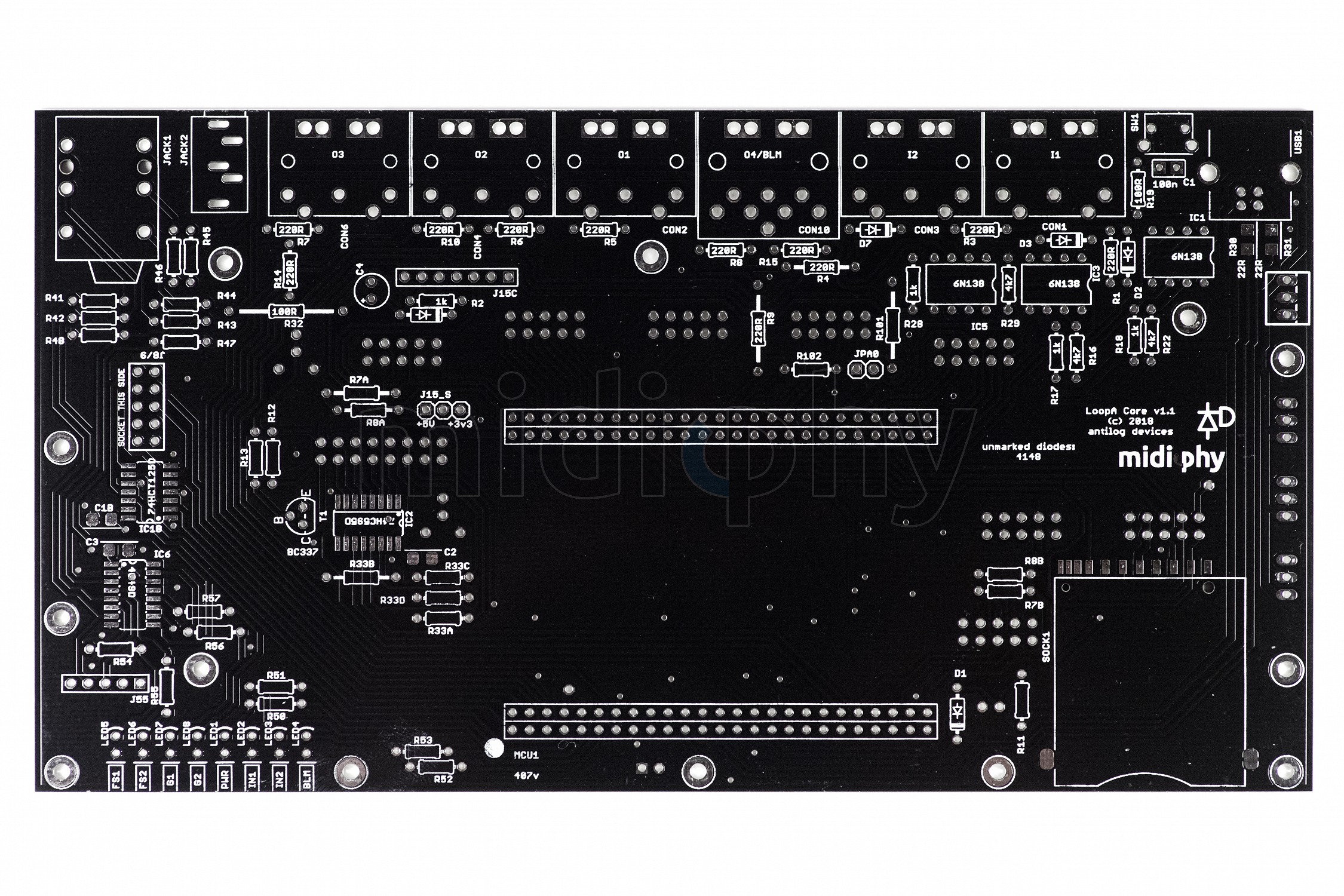
Find a few PCB shots of the three to-be-stacked and hopefully final LoopA PCBs attached:LoopA Core PCB v1.1 - note the additional 6N138 optocoupler for a third MIDI IN (2 normal INs, one BLM) and the moved SD-Card slot that would open up an option for a nice "pro" metal case made my Adrian (with wooden sidepanels) :). But nothing confirmed, yet, just the acrylic variant for now.
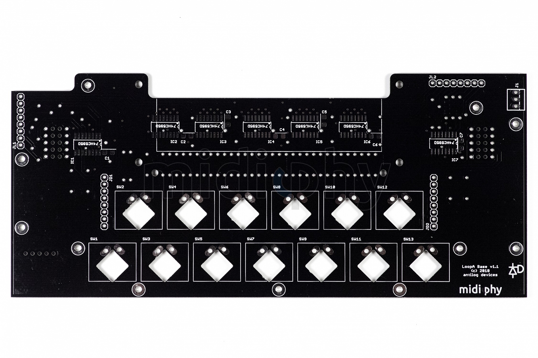
LoopA Base PCB v1.1, with improved interconnectors
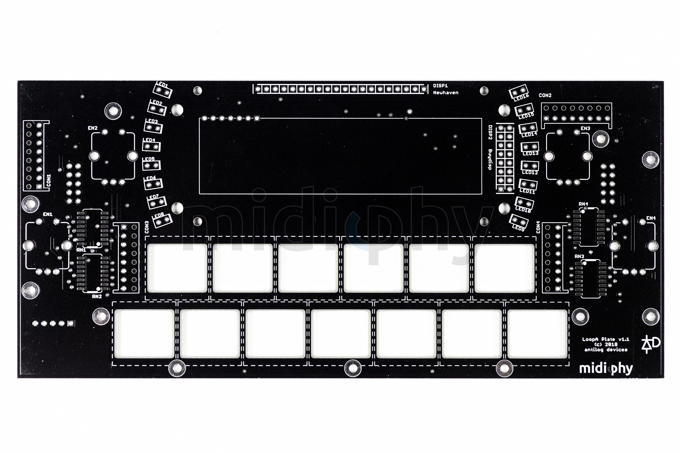
LoopA Plate PCB v1.1, with support for two different OLED manufacturers:
Many greets and enjoy!
Peter -
Sneak preview of the new Seq V4+ UI PCBs & essential parts kit - arranging that stuff on the photo table took, well, too long! :) After the first few shots were in, the little one stormed the room and rattled on the table, she is cleary no fan of ordered stuff :)
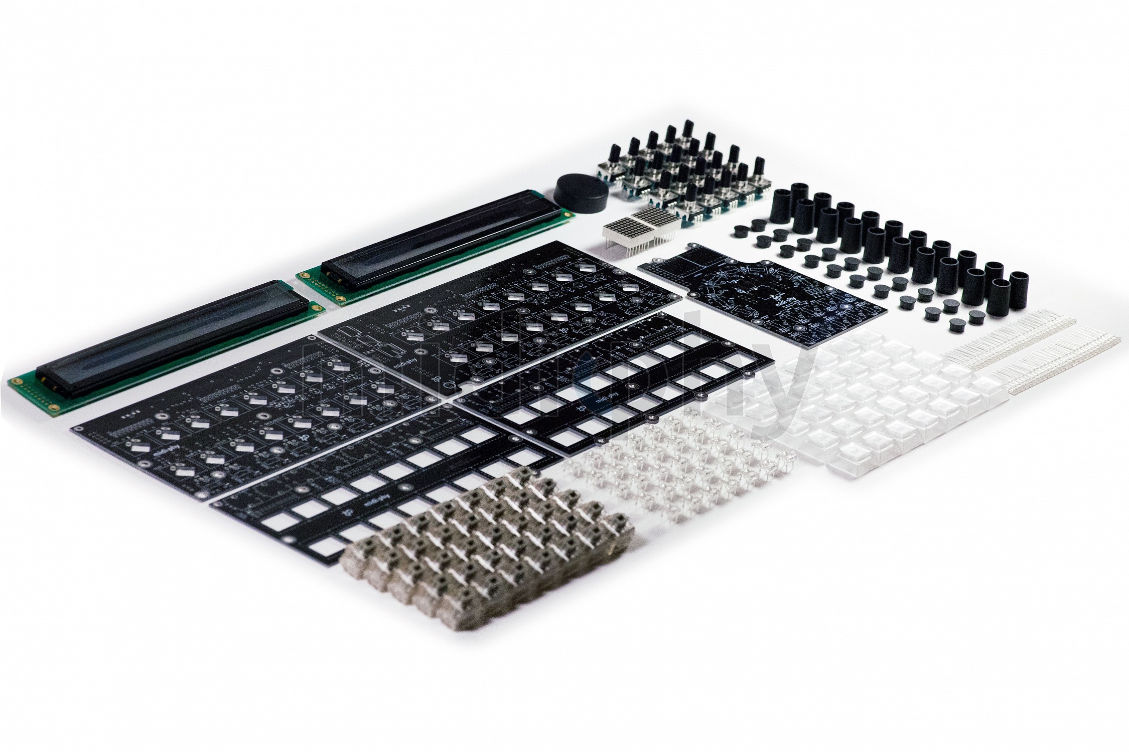
We'll be going to holiday soon (a bit delayed shipping in the shop, sorry!). Meanwhile, Andy is working on the validation of these new v4+ UI PCBs, and after all of that, we hope to be able sell this new UI kit (probably somewhen around mid October). By then, there should also be some progress on the case. Generally it all looks good - it should be possible that you can have a working v4+ under the 2018 x-mas tree :)Many greets and enjoy!
Peter -
Many OLEDs depending on the cap/resistor reset line do actually need a power down/power up phase (try unplugging from USB, no MIOS studio needed for correct start). That is because a successful display init depends on the hardware reset mechanism via cap & resistor. For the new LoopA boards, Andy has invented a solution, how the reset switch will also perform a hardware display reset without the need of powering down/up :).
If this was not the problem, please ignore :).
Many greets,
Peter -
36 minutes ago, Antichambre said:
Hihi, this Nudelholz will become famous, can we get a picture of it ? lol

Haha, it's definitely too bloody to show here!
@roschthanks a lot! :)
What we can show, is progress on the case! Adrian sent us this pic of the unpainted left-hand-jogwheel version directly from his workshop today. So, that's how the (probably) final case looks without paint/labels, during assembly/fit test. It has been slightly reduced in height to fit properly in a 3U rack, as an alternative to using it in normal desktop mode. It also features the cutouts for the beat LED and the two new 8x8 matrix LEDs (TPD).

Now, while the cases are being painted, labeled and stocked, you can think about whether you rather want the left-handed or rather the right-handed jogwheel version
 .
.
Enjoy and have a great day!
Peter -
Thanks, Bruno, it is great to see, that there is interest in the SEQ out there! Amazing response!
Many greets,
Peter -
While being a pacifist, i've got to say, that the M16 Interface wiki graphics is awesome! Well done! :)
Many greets,
Peter -
Great job! Looking fine & nicely compact!
Many greets,
Peter -
Ok, no problem, can write down my thoughts of the v4+ vs the v4, trying to be as neutral as possible.
But first of all, thanks so much for the facebook ads, Bruno! :)
We got a few new youtube subscribers within the last hours, so I was wondering what was going on, hehe! ;-)Regarding the v4+, by coincidence, i have given it an extended test-drive last night, just the v4+ and a Kawai K3M (that happened to somehow come to a rest on my doorstep lately, i really don't know how it happened!!! :). Gladly, the better half did not take note of it yet, otherwise the Nudelholz would have been swung at my poor head again! :)).
Differences of v4+ to the v4. Really, this is not meant to be a sales text - we fortunately don't depend on selling the kits (as we have other jobs) and also hope to be able to provide fair prices, long term. We do it, because we love these things!
Key differences v4/v4+, personal viewpoint:
* The Matias switches with proper large-scale keycaps themselves. In my opinion, they are just so much better than the previous generation of switches/caps used in the classic v4s. If you like mechanical keyboards, it is a dream! In computer nerd talk, to me it feels like an upgrade from HDDs to SSDs :)
* The second row of matias switches and the new "v4+" selection row mode, that can be chosen using the right-hand mode selection "wheel". Imho, it adds a whole level of interactivity while eliminating a lot of page-switches. E.g., last night, i spent probably an hour in the "transpose page" (that is controlled with the primary "GP" row of Matias switches and the encoders). Using the new selection mode wheel, i also at the same time ended up in "Selection: Mute mode", that is then assigned to the secondary row of Matias switches. Now, on a single SEQ page you can mute/unmute single tracks, while also transposing whole groups of selected tracks - that was really a lot of fun :). On the v4, this would of course work, too, but would require menu page switches for every new mute/unmute or transposition change, here you can just stay on a single screen and use the 32 matias switches for both functions at once. As the mode wheel acts as a mix-in feature, you can effectively control two things on a single page and there are lots of combination possibilities.
* Direct track access. Yes, i had grown used to the four+four Seq v4 Group and Track buttons, but using 16 buttons to directly choose a track or a multi-selection of tracks, that will also be highlighted via backlit Matias switches, is a big advantage.
* The look & feel. Ok, i only have a shabby old selfmade v4 and a secondary selfmade quite flat v4, but the OLEDs and Adrians nice metal case, as well as the integration of every PCB in that really compact case feels good. I have to admit, that i really love the VFDs on my my ancient v4. But the OLEDs also have zero latency/ghosting and look fantastic in white, i will adjust to them in time! :)
* The (possible) color bling. Ok, this is a personal preference :).Other than that: if you have a v4, and if you like it and if the keys are not failing: keep it, it is great!
Many new features of the v4+ will likely be instantly available as a function for the v4 as well, if you have a new STM32F4 core in there.--
Regarding prices: as Andy wrote, we are currently estimating around 700-750€ in total costs, but it is not fixed yet, that sum is likely to be split up into:
* Core PCBs + essential parts kit ~ 99€ (available in the shop)
* UI PCBs + essential parts kit ~ 299€ (working on it, validation is ongoing, all parts in stock)
* Case ~ 159€ (Adrian is printing the new case labels to test them this week, the case has been adjusted for better optional 3U rack integration)
* Mouser parts ~ 150-200€ (that position is a bit unsure yet and is just an estimation)The UI kit is a bit expensive, as it contains the OLEDs (~100€ for both), the Matias switches, keycaps and Superflux LEDs, as well as five large-size PCBs and two LED mini matrices. But it effectively also contains a TPD, that is integrated in the case and uses up the last bit of available space (much to the dismay of Andy and Adrian, sorry guys, that i had that last-minute wish, i really feel bad about it, but you would not have needed to incorporate it, despite me begging for it! :))
The Mouser parts could probably be optimized to drive total costs to sub 700€, by sourcing from cheaper parts sellers, but we will only provide the Mouser "master" cart. While i personally had good experience e.g. with sourcing cheap resistor/cap kits from China, and e.g. MIDI connectors can be bought for a lot less than the mouser price, there are different opinions to this. I would say: you will probably build this only once, to last for at least a decade or two, so i'd recommend to use the best parts you can source!
Many greets!
Peter -
3 hours ago, mcmurray said:
Hi Peter, thanks for the Mouser BOM!
Is there any mechanism with your website which could alert us via email when the complete kit (minus Mouser components) can be ordered?
Definitely interested. Cheers.
You are welcome!
Make sure to refresh the BOM, as some gremlins mixed up the crystals for the I2C PCB, 20 MHz instead of 10 MHz are needed. We've instantly updated the BOM and notified all kits purchasers, our apologies!
Regarding your question, yes, a notification feature when something is "back-in-stock" is definitely planned, but it will work only, if a product is already available. Will think about it, how it could be best incorporated in the case of not yet existing products.
Many greets,
Peter -
A little update:
Finally, we have finished the bill-of-materials 'bot (nicknamed b.o.m.b.
 ), that generates complete BOM lists and parts placement/solder guides, for each PCB. It also automatically aggregates those lists for multiple PCBs contained in a kit and creates mouser-cart compatible text output, that can just be copied & pasted into your mouser cart for your convenience. The idea behind this effort was, that you should be able to get everything needed for a build on mouser and midiphy only, and that it should be very easy to import needed parts into the shopping carts.
Hope you enjoy the reduced time for parts sourcing :)These BOMs have been derived/automatically created from the PCB CAD master files. In theory, they should be good: I tried to double-check every part during its creation in the parts database, but we would be glad, if someone could externally validate the parts list, to see if the 'bot works correctly, thanks a lot! :)
https://www.midiphy.com/en/shop-details/0/1#bom
There is a copy & paste link to conveniently put all necessary parts (from all PCBs) into your mouser cart, just follow the link to mouser, you might need to login at mouser first before the "copy & paste" text window appears.
If you test this order from mouser, please give us some feedback, if every part was correct, thanks a lot!Now, on to the UI PCB & parts kit and to the case finalization :) - it will still take a bit of time, but we are confident, that you can haz all of your Seqv4+ parts and start building during autumntime or early winter in 2018 :).
Many greets,
Peter -
Hi there,
the MB6582 is great, you will love it!
A few answers, just the ones i could directly answer :)
* personal opinion: regarding a mixed SID setup: i'd recommend to go for all 8580/6582, the filters are just better, the noisefloor of the 6581 is higher and imho the "flexibility" to divide it up is not worth the "cost" of not being able to play four near-identical sid stereo voices in poly mode.
* power supply: recommended to change it, because the 5V vreg can (and will, i have a defective C64 original PSU here :)) go haywire over time and will burn your SIDs and maybe the PICs... 11.06 V AC is not necessarily cricital if it was not measured under load. The PSU might be ok, but for long time use, it is highly recommended to replace it. There are recipies around this forum how to do it, look for a solution from orange_hand to go for an energy efficient one :)
* OLEDs work, see Izze's thread:
* A case fan is imho not really required if you use 8580/6582. I had my MBSID in use since 2010 without it, not a single SID failed so far. Just use thermic glue and normal IC headspreaders for classic DIP ICs. Fans are known to add noise to the audio outs and physical "airflow" noise in your studio.
* 1.5mm acrylic will not be stable enough, got to go for an aluminum frontplate, it is expensive, but it will last!
---
Sorry for incomplete answers, you should be able to find answers to most of the other questions here on the forums.
Many greets, Peter
-
Thanks!
Regarding BOMs, yes, we are working on an integrated solution, that will directly export parts from the PCB CAD files into the shop. For a first look of a completely auto-generated bill of materials, look here:
https://www.midiphy.com/en/shop-details/138/2/
(it is yet incomplete, some parts are still missing, still working on it :))
The cool thing about this method is, that it should be theoretically completely error-free! No copying and pasting, no google spreadsheets, and so on. This method also allows to aggregate necessary Mouser parts even for kits consisting of multiple PCBs! There will be a "download mouser cart text" file button below each BOM table and the generated text file can just be copied&pasted it into your shopping cart at mouser. Will try this method for the video documentation of the UI interface PCBs myself, to see if it works and if any parts were missing :).
Regarding builders:
We cannot provide built units for legal reasons.
But there are known and reliable builders around, that you could hire on a personal basis. Some of them have even registered on this thread. A recommendation is to find someone from your country to minimize shipping costs and do a phone call first. If you found someone with a track record of built MIDIboxes, then everything should work out, the build process will be fully video documented and should (hopefully) be fairly easy to follow.Many greets,
Peter -
Thanks a lot for testing Bruno, and sorry for spamming this thread with shop tech discussion, if there is more to be discussed on that matter, we should probably move to PMs! But your feedback was really helpful and very welcome - because you develop a bit of a "developer blindness", when you work with such a system for years, it is great to "see" it through new users eyes, and hear any comments. Thanks again! :)
Some remarks:
* The now blank address fields are expected, this is to be explained with the changed address form, i.e. it could not remember everything, as it is now stored to a new dataset.* But: your updated address will be remembered after your first order, no way to change it in the customer center currently (other than deleting your account and reregistering which is a brute force method, but should also work! :)). The shop always remembers the last valid order address (or the first address entered when creating a customer account.). In short words: you just need to enter your address normally for your first order. Then you should be set and it should remember it.
* The cart should be remembered during your web session, as long as your browser window is open. We might add "persistent cart storage" a bit later on.
Good feedback on the country list, keyboard searching helps for sure! The shipping country list is also growing larger by the day: as that request came up, we've now added more shipping countries, especially Australia and New Zealand. :).
As shipping to these countries is not the cheapest (prices identical to DHL prices listed on their page), we would recommend everyone interested in a v4+ from these countries to wait for the availability of the v4+ cases. Then everything crucial should fit in an insured and tracked 5kg parcel and it won't be that expensive anymore.
For the EU or for everyone wanting to have a functional v4+ (without case) as soon as possible: Andy will test the new UI PCB boards as soon as humanly possible (it is a lot to build and verify!). And if it all checks out, we can offer the new UI PCBs and all relevant essential parts (like OLEDs, Matias switches and Keycaps) as another essential kit, even, if the second and final video tutorial (which depends on the case) will take a bit longer until it is ready.
Have a great evening!
Many greets, Peter
CC-Looper (4ch controlchange looper)
in MIDIbox User Projects
Posted
Looking good! :)
Just out of curiosity, how many CC samples can you store on a track (resolution)? Will you support more inputs than one CC per track?
I've recently found some unused memory on the LoopA and was thinking of limited CV support, too. But it will be a single CC per track only at limited resolution. So yours will be the dedicated machine for it, for clean filtersweeps and such, no competition there, no worries! :)
Many greets,
Peter