.CID
-
Posts
18 -
Joined
-
Last visited
.CID's Achievements
MIDIbox Newbie (1/4)
0
Reputation
-
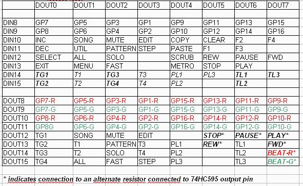
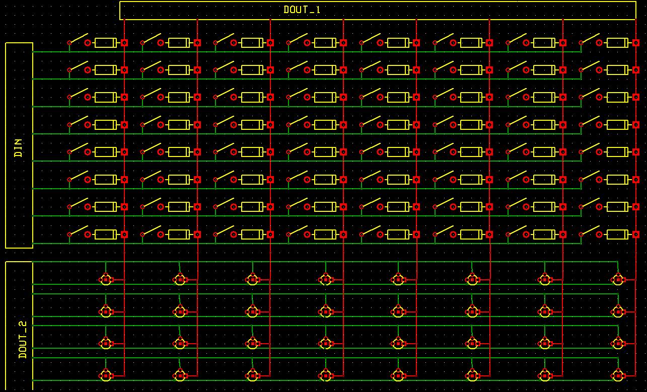
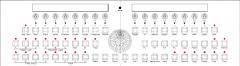
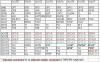
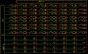
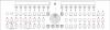
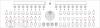
Thanks guys, that clarified a lot. I think I have figured out how to wire the 64 switches, but there's still one thing unclear: beneath the 4 rows of GP LED connections (in the attached JPEG) there is 4 rows of what seem to be duplicates of the key names, I assume these are the LEDs fitting those keys. I intend to use separate modules rather than building a PCB like Wilba's wich includes all of them since I'm quite the newbie at this. Does the "<i>* indicates connection to an alternate resistor connected to 74HC595 output pin</i>" mean there should be a different resistor than 'standard' on a DOUT module? I've also attached my 'simple' version of the schematic, this is how I now figure the key wiring should be. Have I connected the diodes correctly? (I find it too hard to tell from Wilba's PCB PDF) Thanks for the hints and tips so far! ----- EDIT: accidentally there's 4 rows of bicolour LEDs in the wiringTest.JPG, this should be 2, obviously. EDIT2: I found http://www.midibox.org/dokuwiki/lib/exe/fetch.php?media=mb-6582:mb-6582_cs_din_wiring.pdf, wich clarifies the diode question.
-
Thanks Findbuddha, after what you told me I found this. If I understand correctly (I am completely new to this subject) all encoders are wired to DOUT pin 0 and two DIN pins, and a bunch of buttons are connected to DIN Unit 2 and various DOUT pins via a diode(or is this diode set between the DIN and the button?) Also, I don't understand the use of Unit 8 (DOUT)yet, but I'll have a go at that tomorrow.
-
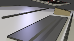
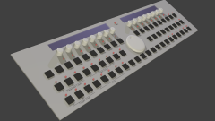
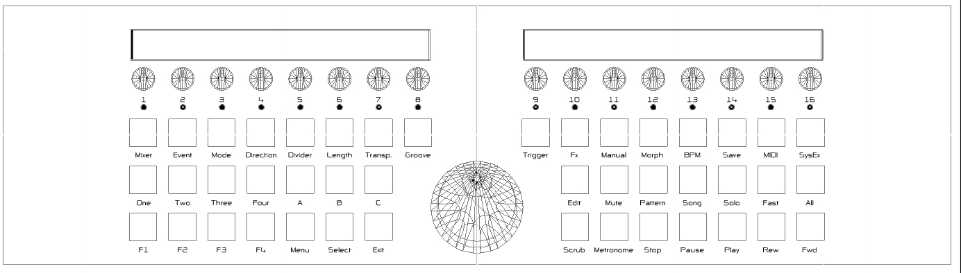
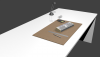
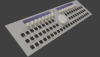
Hi, me again. I'm trying to figure out the wiring for all of the keys, and I'm running into some difficulties. I don't really understand the MBSEQ_HW.V4 file, but I think I can manage the pin assignments if I take a closer look at it. However, can someone tell me what the mentioned '8x8 BLM from Wilba's frontpanel' is? I don't see a BLM on the frontpanel, at least not one like the 16x16+X BLM. Are these the keys that have LEDs next to them? oh, and for those like me who like images, another render just for the heck of it ;-)
-
I think this qualifies as a ROFLCOPTER. nice find :")
-
-
-
 The idea was to make the BLM in a 'drawer' so both it and the CS are reachable. I think the other way around would mean that 'playing' using the BLM would be some hell of a lot harder.
 -
Hehe,ok. Good luck on finishing yours, that topic of yours is really nice to read! Ah, thanks. I'll edit my layout to fit that : ) *10 minutes later* There we go! I also buried the datawheel a bit deeper to get some better access to the moved buttons. I might bury the encoders a bit deeper for some better viewing of the LCDs. Now to find a function for those two extra buttons ;-)

-
I tried to combine the "MENU+.." buttons so they should be easily accessible, I'm glad someone with more experience thinks it works. Wich ones would that be?
-
I included Hawkeye's comments, but since I don't know the SEQ that well I may have mistaken some functions. Comments please : )
-
thanks for the tips! as for the buttons:I had the ones from the attached PDF in mind while making the 3d model, but I found out they can't be used with PCB switches (only with €1+ other ones). I'm now trying to find matching caps for https://www.distrelec.com/ishop/Datasheets/03565306.pdf or the similar ones from Conrad( http://www2.conrad.nl/goto.php?artikel=700622 ), but although the PDF form Conrad says 12.4x12.4 mm caps for the switches exist I can't find anyone selling them yet. *** EDIT *** I've finally found a website selling both square caps and switches that suit them =D I'll be going with this switch and this cap. Since they're 12x12mm instead of 14mm I'll be having a bit more space to mess around with : ) 5AC5-2,5AC52,,Cap black,Pla..pdf
-
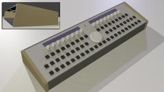
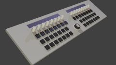
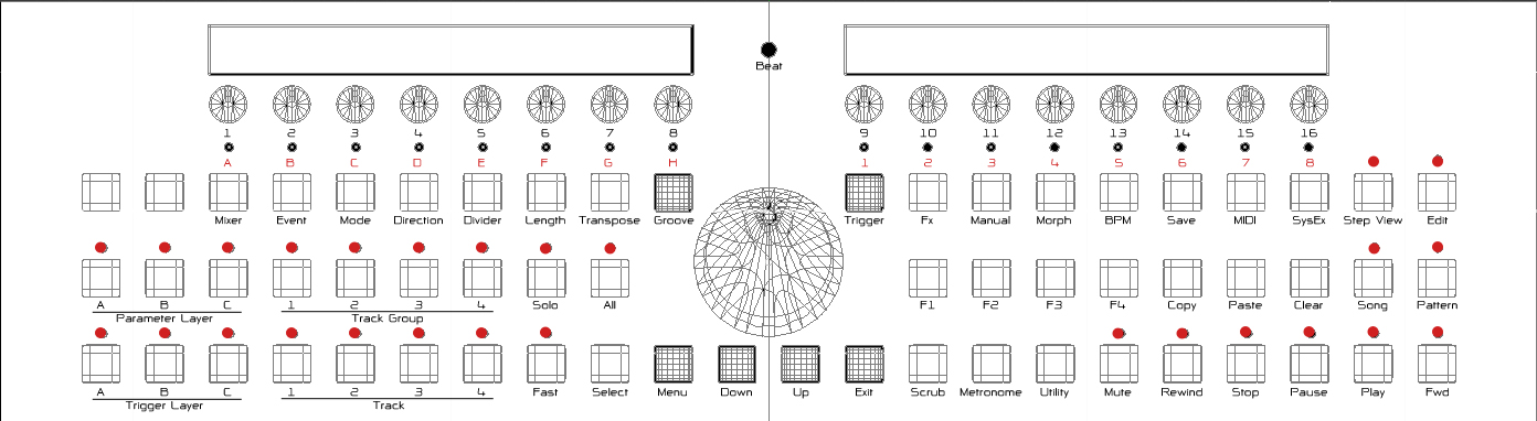
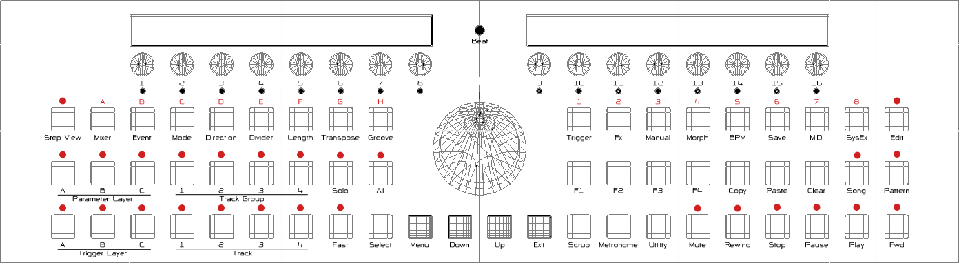
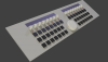
Hey all, being an IDE student, I'd like to come up with my own control surface rather then build one someone else thought of. I know, it's stubborn and maybe not the best idea, but I'd like to give it a try nonetheless ;-) This is what I've come up with. It's -heavily- based on the TK/Wilba layout, but with differnt buttons and caps. I'd also like it to be symmetrical because I think that looks great. The only problem is, that I've never used a sequencer before (just some softsynths) and therefore have no idea whether this layout is comfortable while playing. What do you think? Also a 3d render of the entire thing to clarify what you're looking at: Kind regards, .CID ***EDIT*** I just noticed I based this on the v2/v3 button layout rather than the v4 button layout, so I'm missing a few keys. Still, comments are uch appreciated!
-
Hey, after I found this topic I discovered these encoders at the same website: http://www.pollin.de/shop/dt/NjE2OTU3OTk-/Bauelemente/Passive_Bauelemente/Potentiometer_Trimmer/Encoder_Noble_RE0124PVB17_7FINB_24.html 0,50€ each, without a built-on knob (a plus for me, I like to use some prettier ones ;-] ) As far as I can tell they are suitable for the SEQ v4,can anyone confirm this? I'm just a poor student (boohoo, QQ, etc. hehe) so if these are an option I'd be very happy since it saves a lot of cash.
-
Hello all, first of all, thanks for doing all this work. I've been reading through the entire thread, and you've really done a lot so far. I've added myself to the bulk order list (but only figured out how to unhide my email address a few days later), so I'm now waiting for anything to happen : )