

Elektruck
-
Posts
279 -
Joined
-
Last visited
-
Days Won
10
Content Type
Profiles
Forums
Blogs
Gallery
Everything posted by Elektruck
-
Hi, I'm playing with Midibox NG and would like to add some touch sensors to my next project. I'm aware that they were supported by MIDIbox64 and NOT by MIDIboxNG. After searching the net I came across this little board: https://learn.adafruit.com/adafruit-cap1188-breakout/ I would add this to my MIDIbox NG but I'm not sure how to. It has I2C, ISP and outputs that go from 3V to GND when touched the corresponding input. On adafruit there are some examples but they are with Arduino, i don't know how to use them. I'll start experimenting with adding the outputs to my DIN's an see what happens, but all help/idea's are welcome!
-
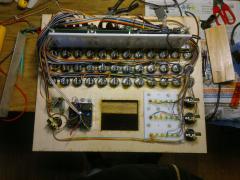
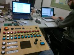
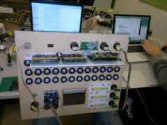
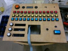
The Mayhem Machine is a video/music sequencer I build together with Martijn Verhallen for video artist Marieke Verbiessen. Martijn builded the complete Machine in Max/MSP and I made the hardware controller for it with MIDIbox NG
-
-
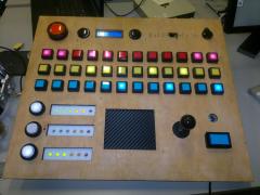
From the album: Mayhem Machine
Mayhem Machine ready! -
From the album: Mayhem Machine
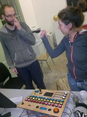
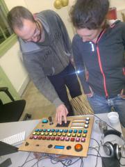
Martijn (Max/MSP-programmer) & Marieke (video-artist) @ the Mayhem Machine -
From the album: Mayhem Machine
Martijn (Max/MSP-programmer) & Marieke (video-artist) @ the Mayhem Machine -
From the album: Mayhem Machine
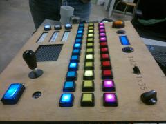
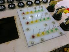
LED there be light! -
From the album: Mayhem Machine
wiring -
From the album: Mayhem Machine
-
From the album: Mayhem Machine
-
From the album: Mayhem Machine
-
From the album: Mayhem Machine
-
From the album: Mayhem Machine
DIY ledbar VU meter -
From the album: Mayhem Machine
-
From the album: Mayhem Machine
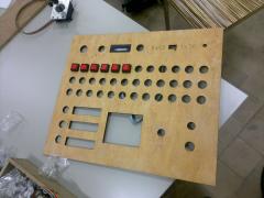
just started -
From the album: Mayhem Machine
testbank -
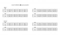
I made a pinout sheet for my own clearance. Maybe someone can use it. It's just for the R3 boards!
-
From the album: Elektruck
Here's the pinout for SmashTV's DIN en DOUT REV.3 boards. It's different than R5 AND... the pinout labelling of the R3 DIN Shift Registers 2, 3 & 4 is wrong on the board! -
That's exactly what I did and ment by shortcutting the pins to ground. It had the same results, so I knew it wasn't just bad wiring. But... problem solved!!! I used 2 different DIN boards from SmashTV, R3 and R5, they look exactly the same but they aren't! They have a different pinout, like in reverse. So that's why my buttonboard was good first time (years ago), but after connecting it to a different DINx4 board the buttons react like 2,1,4,3,6,5,8,7. I resoldered my buttonboard, then it was good again with a R3 board except for the strange mirroring on SR 2, 3 en 4. Today I reconnect it to a 'new' R5 DINx4 board and my buttons react like 2,1,4,3,6,5,8,7 again, but on all 4 shift registers the same, woha!!! After beep testing the SmashTV R3 DINx4 board with my multimeter, I found out that the labeling/pinout of D0,D1,D2,D3 of SR 2,3 and 4 is wrong (mirrored) on those boards. All really confusing but I'm happy it's not just my stupidity. Thanks for the replies! Cheers, Roel
-
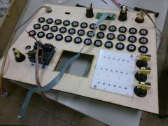
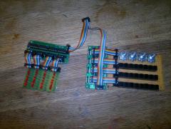
I think you're wright about building a new core won't solve the problem, cause the problem is in some basic (wiring) thing. But sometimes I get stuck and starting over again clears a lot. When I first soldered my buttonboard, see picture, I soldered it wrong. My buttons were like 2,1,4,3,6,5,8,7. So I re-soldered the first row and checked it again. Now it was good, so I copied the other rows. After I plugged them in I noticed the strange behaviour like I mentioned before. I thought I soldered it wrong again, so I attached button row 1, wich was good on SR1, to SR2 and it did the same strange mirror thing. So I'm quite shure the button rows are soldered correctly. I even tried to shortcut the pins from SR2 to ground and see what happens, and the mirror thing is still there. That's why I started thinking I maybe changed the DIN pinout on the software side. But I guess that's not possible,I installed a new bootloader and formatted the SD Card, and the problem is still there with the new DEFAULT.NGC Anyway thanks for your replies, I hope tomorrow will clear things up.
-
From the album: Elektruck
DIN/DOUTx4 -
That was my expectation also, and SR1 is like that, but SR2,3,4 behaves indeed like if D0..D3 are mirrored. I did test it with MIDIO128, and it shows the same mirroring. I couldn't see the button ID, but I looked at the generated notes. SR1 D0....D7 shows C,C#,D....G# but.... SR2D0...D7 shows D#,D,C#,C,E,F,F#,G# I just don't understand, tomorrow I'll solder a new coreboard, for an other project but I'll check if my buttons reacts the same, if it does I'll try your idea Marxon.
-
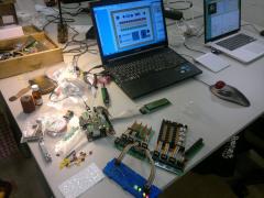
I've made a prototype/testboard with a STM32F4 board, running midiboxNG. I've connected a 2x40LCD, a SCS board, a DINx4 with 24 buttons and 4 encoders, a DOUTx4 with 32 leds and an Ainser board with 8 pots, and a SD card of coarse. After changing the DEFAULT.NGC to activate the Ainser module and the 4 encoders everything seems to work like a charm. But I got a strange problem with my DIN SR pinout and the button/encoder ID's. The first SR acts just normal, like I would expect it to do. D0=Button#1, D1=Button#2, D2=Button#3 etc. But SR 2 acts like: D0=Button=Button#12, D1=Button#11, D2=Button#10, D3=Button#9, D4=Button#13, D5=Button#14, D6=Button#15 and D7=Button#16 SR's 3 and 4 acts the same as SR2. I tried all things I could think of, like changing the buttons boards, changing a DINx4 board. I've uploaded Midio128 with the same result. After that I flashed a new bootloader, formatted the SD Card. I made a new 'button only' NGC file with RESET_HW to check the button ID's but the problem stays. I can't find were to check/change the DIN SR pinout/Button ID's. I can only find that Button ID1 is equal to SR1D0, Button ID2=SR1D1 etc.. but in my case it's not after SR1?! any help appreciated! Cheers, Roel
-
Thanx for the tip, I saw the site before but it's great, with pcb-layouts and and hexfiles for PIC's! really cool, gonna check this out further. Thank you, you made a nice one too. Great news that it'll read wave files!
-
 Thanx man!
 -
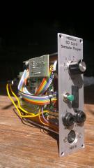
Here some pictures of my newly build SD Card sample player module. It's the smallest module in my modular, but so powerfull! Till now I only used one bank full with hardcore-basskicks,kicking through some analoge filters, really lovely! I made a reset button on the module cause when you change MicroSDCards it needs a reset. I don't need the pushbuttons on this kind of module, midi in works great. But I wanted to make an other module for using in a live-theatre show where I have to trigger some (only2 )sounds. Now we use two CD players for that, and it would be great to swap those CD players with this tiny sample player. But the audiofiles are 5 minutes each and I noticed this SDCard sample player only playes a couple of seconds/sample, or can I change that somewere?