Search the Community
Showing results for tags 'scs'.
-
From the album: Midibox NG
-
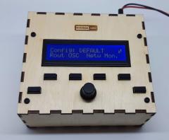
Hi all, today I would like to share my experience with encoder on scs, the board version made by ilmenator (semper laudetur), attached to MBHP_CORE_STM32F4, midibox_NG project. I noticed that sometimes, especially when fast rotating my encoder (I choosed a bourns PEC12R), midibox_NG detects more events than really executed, or worse, events in opposite verse. Using an oscilloscope I saw many spikes on encoder pin, duration shorter than 1 ms. Following suggestion on attached datasheet (I hope attaching this document is permitted, I did not find any rule against, but if so I will remove it immediately), second page, bottom right, I modified circuit with some patches. Now it works perfectly, but I have some requests/suggestion to improve design if anyone knows, please tell me if there is a NGC parameter to allow debouncing on encoder inputs, otherwise for TK, please modify SCS scheme to suggest RC filter usage; for ilmenator, please modify your board design and allow to connect necessary 4 resistances and 2 capacitors. Thanks to anyone, Regards, Cristiano PEC12R.pdf
-
From the album: Panel-Work
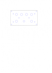
SCS Acryl Termplate for ITT D6 -
From the album: Panel-Work
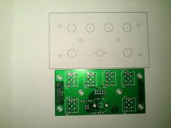
all in the middle -
TK has already mentioned it in I have created a PCB for the MIDIbox Standard Control Surface (SCS) that does not require any shift registers and connects directly to J10A of the core board. The SCS module integrates nicely into the MIOS framework, check out tutorial #027 if you want to learn how to use this in your own project. Or just use it for a simple user interface in your MIDIBox CV V2. I have tried to accommodate footprints for a number of different switches: I succeeded with the Marquardt 6425 series, the ITT Schadow D6 series available at Reichelt, and the E-Switch 612-TL1100 series. That makes the board a pretty universally usable PCB, I believe. Also, it will align perfectly with a 20x2 character LCD, which should sit just above this PCB in the front panel. The bare PCB is about 98x49mm in size: Here are the different switches in place: A full documentation can be found in the Wiki. PM me if you need one of these boards for your project. Best, ilmenator
- 3 replies
-
- SCS
- Tutorial #027
-
(and 2 more)
Tagged with:
-
Hi all, as a by-product of my latest project, the MIDIbox Matrix (a MIDI router with up to 56 in- and out-ports), I have created a PCB for the Standard Control Surface or SCS. This little board assumes that you are using a 2x24 character LCD and 4 items per menu page. This is slightly more character space per menu entry than what TK is using, however the code is fully configurable to handle this. Personally, I find the 5 available characters per menu item much more comfortable and less cryptic than lower character counts. Assuming that you want to use both shift and exit buttons for navigating the menus, the board is prepared for one extra button to the left of the display. Also, two additional encoders (with push function) can be used - but these can also be left out, obviously! Specs of the PCB are documented in the WIKI. I have 4 of these available, but would be willing to order more if there is enough interest. Asking price is 13€ per board, plus shipping costs. Drop me a PM or answer in this thread if interested. Best, ilmenator
- 4 replies
-
- SCS
- Standard Control Surface
-
(and 1 more)
Tagged with:
-
Because my Waldorf Midibay became too small for connecting all of my MIDI equipment, I went ahead and designed my own MIDI matrix / programmable patchbay. The modular MIDIbox Matrix has up to 56 input and 56 output ports and provides a smart solution for the fact that not all MIDI equipment is usually located in the same rack or corner of the studio space. MIDIbox Matrix features break-out boxes (BOBs) that give access to 4 MIDI in and 4 MIDI out ports at a time. These are connected via 9-pin serial cables to the main unit and are designed to be conveniently placed in the back of your rack, e.g. attached to the inner sidewall of a rack enclosure with screws or velcro tape. This means that instead of running 8 MIDI cables to the MIDIbox Matrix in order to connect four synths, you only need a single, cheap serial cable from your side rack to the center point of your matrix. Two BOBs each connect to a single I/O board, which does all the level shifting and signal refreshing. Up to seven I/O boards can be attached to the heart of the MIDIbox Matrix, an FPGA-based switching and routing logic that is controlled via a core board such as the STM32 or the LPC17. As the system is highly modular, it is possible to start with a low port count (4) and then increase the number of available ports by simply adding I/O boards and BOBs as needed. Fully loaded, i.e. offering 56 input and 56 output MIDI ports, the MIDIbox Matrix consists of 1x FPGA board 7x I/O boards 14x BOBs plus a core board and the PCB holding the user interface. This is how a BOB looks like in my setup: Software-wise, this is almost ready - everything works as expected, just the PANIC button has to be implemented in the next weeks, and some code cleanup will be necessary. You can find more documentation in the Wiki if you are interested. Kind regards, ilmenator


