Search the Community
Showing results for tags 'MF_NG'.
-
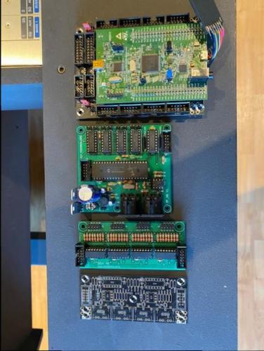
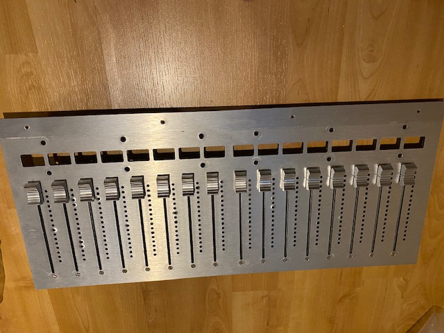
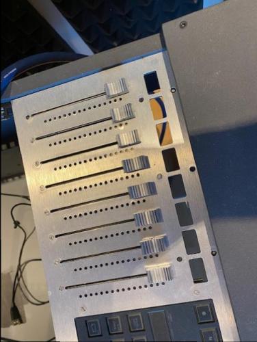
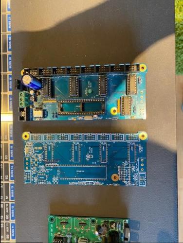
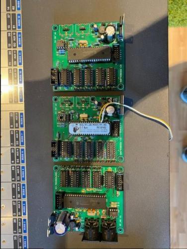
Hello all, After a long time with practically no time to continue my project I have decided to downscale my project. That's why I'm selling a lot of stuff: 1x STM32F4 Core Module Board+ STM32F407G-DISC Assambled, tested and working (no sd card), use at own risk 1x MF_NG Module + PIC Assembled, tested and working, use at own risk 3x MF_NG Module + PIC Assembled (1 board missing 1 IC), not tested 1x Custom MF_NG Module (no PIC) Partly assembled, not tested 1x Custom MF_NG Module (no PIC) Not assembled 1x DOUT Module Assembled, tested and working, use at own risk 1x MIDI IO Not assembled 26x 100mm Alps Motor N fader (some o-lead, some normal lead) Unused, only mounted, no caps 2x 19 inch frontfpanel from dibond (aluminium, plastic, aluminium) 1 with cutouts for 16 faders, OLEDs and led VU meters 1 with cutouts for 8 faders, OLEDs and led VU meters and 2 Steinberg CMC cutouts Preferably selling it as one lot, but I might consider selling individual items. (I might keep de STM32F4, but not sure, defends on the offer) Make me an offer. Shipping costs for buyer.
-
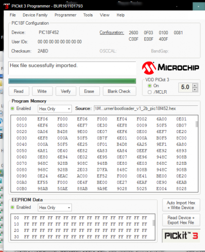
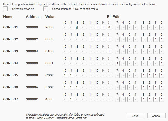
I know there are a lot of posts about this already, but I have gone through the troubleshooting guide and am still left with some confusion as to whether I am doing everything right. I am getting 5v everywhere on the mf_ng module. I've tried 3 different midi interfaces. a "usb uno" , presonus firestudio project, and rme raydat I have tried programming a pic18f452 and pic18f4523 using the pickit3 and the pickit3 software which is running in parallels. according to the the pickit3 software, the bootstrap upload has been successful, but I still can't connect to mios. When testing the grounds on the capacitors connected to the crystal i get 4.97v on one leg of either capacitor. I'm not sure if that is normal or not. But both capacitors get 5v on one leg. The crystal I am using is from Reichelt when I connect the pic into the socket on the module, I only get 3.23v on pin 14 of the pic, pin 12 is getting 4.97v (with the positive terminal of the multimeter connected to Vd of J2, and the negative terminal connected to the pic pins and capacitors) I've tried all the midi loopback tests and they have all been succesful 3.23v on pin 14 doesn't seem right to me. Maybe that is the problem? I'm not sure how to fix that though if it is I included some screenshots of the pic programming. The bit values are all default, do I need to change those at all?
-
I am brand new to midibox, I don't have any modules yet, as I am trying to figure out which ones to get exactly, I haven't found a sure answer to what I'm looking for specifically by looking in the forums and the general information on the ucapps site, maybe someone could help. I'm trying to make a controller for Pro Tools using 3 MF_NG modules , for 20 channels/faders total since it would be installed in an existing 20 channel console, but I'd also like to have buttons and leds for record enable, channel automation, as well as transport controls and automation selectors (read, write, latch, etc.) as well as leds for the record lights, which for me would be about 60 buttons, and 20 leds at least for the record enable lights. at least Ideally it would use mackie HUI, but I would be fine with using MotorMix if that works better. I'm trying to find someone here who has successfully made a controller with both motorfaders AND buttons/leds who could let me know what modules I would need My first thought was to get a STM32, and then connect the MF_NG modules and DIN and DOUT modules, but in the MF_NG thread there was a post that made me think that might not work. I posted the quotes below, they are from 2012, maybe this is dated? Would it be different since I am only using 3 MF_NG modules? Could I use just a STM32 or would I have to use an LPC17 and MIDIO128? If I did need to use the MIDIO128, would I have to use the LPC17 or could I use it with a STM32? My understanding is that the STM32 is an upgrade in a lot of ways to the LPC17, and doesn't require an external burner. My goal is to keep everything as simple as possible since i'm completely new to midibox. But since it's Pro Tools we are talking about, things can't be so easy.. Sorry for so many questions, any help is greatly appreciated!! Even if i had to use older modules, that would be okay! I just don't want to get/build the wrong components.. I also wanted to make sure this kind of configuration is something other people have gotten to work in pro tools Here are the quotes:
-
I have 3 MF_NGs linked in a chain. And it already worked some time ago. MIOS Studio does not recognize MF_NG boards, while amidi -p hw:4,0,0 --dump shows incoming MIDI Events for fader movement on all MF_NGs on fader 1. I tried to connect just one MF_NG, but that did not work eather. The boards are not showing up in MIOS Studio, no matter what I do. What am I missing?
-
Hey. This is my first time posting and my first build. Thanks for all the hard work on this project. Very cool stuff! I have a few questions on getting started. I have the LPC17 setup with the SD and working over USB. My configuration is going to be: LPC17 (2) DIN to control 21 Rotary knobs and 20 buttons (1) MF_NG to control 1 Motorized Fader (Alpha) (1) DOUT for LED I won't be using any midi ports for this project, it will be USB-MIDI. I have J4B of LPC17 connected to J11 of MF_NG. From here, I have no idea what to do to be honest. :smile: I would love to make a detailed PDF of the connections to share. I will be interfacing this with ProTools and Reason, what is the best emulation for those? Any help would be amazing. Cheers. -eric

