Search the Community
Showing results for tags 'j16'.
-

STM32F4 SDCARD Reading CID failed with status -256! Solved
gerald.wert posted a topic in MIDIbox SEQ
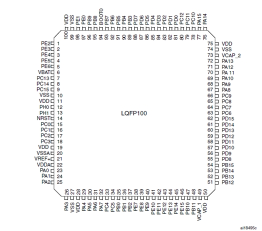
I had been getting the following error from the terminal when trying to access the sdcard on my STM32F4 core: [[35355.231] SD Card Informations [35355.231] ==================== [35355.231] ERROR: Reading CID failed with status -256! [35355.231] ERROR: Reading CSD failed with status -256! [35355.231] [35355.231] Reading Root Directory [35355.231] ====================== [35355.231] SD Card: not connected [35355.232] Failed to open root directory - error status: 12 [35355.232] [35355.232] Checking SD Card at application layer [35355.232] ===================================== [35355.232] Current session: /SESSIONS/DEF_V4L [35355.232] File /SESSIONS/DEF_V4L/MBSEQ_B1.V4: doesn't exist [35355.232] File /SESSIONS/DEF_V4L/MBSEQ_B2.V4: doesn't exist [35355.232] File /SESSIONS/DEF_V4L/MBSEQ_B3.V4: doesn't exist [35355.232] File /SESSIONS/DEF_V4L/MBSEQ_B4.V4: doesn't exist [35355.232] File /SESSIONS/DEF_V4L/MBSEQ_M.V4: doesn't exist [35355.232] File /SESSIONS/DEF_V4L/MBSEQ_S.V4: doesn't exist [35355.232] File /SESSIONS/DEF_V4L/MBSEQ_G.V4: doesn't exist [35355.233] File /SESSIONS/DEF_V4L/MBSEQ_BM.V4: doesn't exist [35355.233] File /SESSIONS/DEF_V4L/MBSEQ_C.V4: doesn't exist [35355.233] File /MBSEQ_C.V4: doesn't exist [35355.233] File /MBSEQ_BM.V4: doesn't exist [35355.233] File /MBSEQ_HW.V4L: doesn't exist or hasn't been re-loaded [35355.233] done. I checked around on the forum and had seen a lot of people having issues with wiring , the card slots and the format on the cards. Mine turned out to be bridged pins under the LQFP100 on the STM32F4 board. Here are the relevant pins if you are having issues as well: LQFP100 P1 PA5 30 15 PA6 31 18 PA7 32 17 PB2 37 24 Here is J16 looking down on it _________ | VS --- VS | -------> to ground | VD --- VD | -------> 3.3V (the STM32 actually only puts out about 3 volts) SI SO | SI ----> PA6 SO ---> PA7 | SC --- SC | --------> PA5 | RC2 RC1 | RC2 --> PD11 RC1-->PB2 (RC1 goes to the onboard SDCard reader or a card on J16 if there is no card in the reader ---------------- RC2 is for a second Card and not needed for most testing. I figured the board was already messed up so I decided to try fixing it. Those pins are super small and hard to work with. There was a dead short between PA6 and PA7 I was able to lift pin PA6 and cut the trace with a razor blade and solder a jumper directly from the pin to PA6. I would think this error would more likely happen from a solder bridge elsewhere and the STM should pass QC. The pins are pretty easy to test as they go straight to the ARM Processor. The also nicely went in order down the side. PA5 was pin 5 on that side of the chip. The white silkscreen on the board makes it a lot easier to keep track of the pins they are marked every 5 pins. The jumper might look a like it is crossing things in the photo but the pin is bent up and out so there is plenty of clearance. I tried solder wik, reflowing the pins, my hot air rework iron, cleaning between the shorted pins with a razor blade, and even removed the header pins hoping the short was there before lifting the pin but nothing else worked for me. -
Hi All, I need more digital outputs, making the J16 connector on the LPC1769 with exit to 128 LEDs. How to make this? I dont want matrix ... I must also not use analog outputs, only analog inputs, the connector J19 can be used the SR 74595? How to make this? TKS!!!
-
I haven't been able to find any reference to this info on uCapps.de and the forum so it's reference info for anyone who wants to connect an external SD card socket and ENC28J60 based ethernet board at the same time. Both of these devices are connected to the core with SPI. While I have been try to get them both to work at the same time I have learnt that SPI can be connected in two ways, "Star" and "Chain". The SD card socket and ethernet module need to connected in a "Star" configuration in order to work. Basically the two devices share Serial In (MOSI) , Serial Out (MISO) and Serial Clock (SCK) signals but each have individual Slave Select (SS) signals. The attached picture illustrates this pretty well.


