Leaderboard


Popular Content
Showing content with the highest reputation on 02/09/2018 in all areas
-
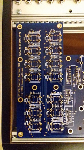
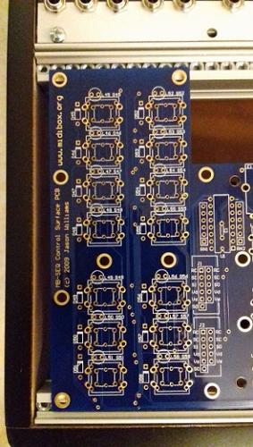
Hi, Just checked Wilba's PCB with my Eurorack case. Not sure how this will fit :/
 1 point
 -
It would be helpful to list the actual PICkit clone first (+ pictures). I use the DIAMEX one recommended here with flying connections (no external voltage) and simply buss powered from my computer. I also went for auto-detect Vdd level (choosing the correct family will ensure this).1 point
-
Well, the 16f88 is supported by the PICkit 2 and you should be able to program one directly on a breadboard. The biggest problem is if you load a Hex that sets the MCLR to a GPIO or uses timers (that use RB6 or 7), so once the code boots you can't enter PRG mode to verify or erase. I would advise against trying to 'force feed' Vpp to the chip as you can't control the timing needed and likely kill the chip. With a fresh chip you should be able to connect the PICkit 2 header, as above without external 13.1V or Vdd, and the PICkit 2 will supply Vdd and Vpp to the chip. If your USB port can't supply the needed current for the PICkit try using a powered hub. This is a very basic breadboard setup (pretty much what I use with the ICD2) : https://sites.google.com/site/picf88/16f88---tutorial Yogi1 point
-
Found it and my led on the AOUT is working... Getting nesr the end.. Yeeha... Posted 16 February 2013 - 13:35 Quote 1 - GND (Vs) 2 - +5v (Vd) 3 - CS 4 - SI 5 - SC Just to be clear, the connections to J19 are: J1:1 -> J19:Vs J1:2 -> J19:Vd J1:3 -> J19:RC1 J1:4 -> J19:SO J1:5 -> J19:SC In addition, the AOUT_NG interface has to be selected in the CV Configuration menu (by default, the AOUT module is configured) Best Regards, Thorsten.1 point