FantomXR
-
Posts
1,035 -
Joined
-
Last visited
-
Days Won
22
Content Type
Profiles
Forums
Blogs
Gallery
Everything posted by FantomXR
-
I'd like to help but I really don't understand what the problem is. What is connected to where? How many keys? Which keybed?
-
Hi @Zam, do you have a photo of the inside of the Juno 60? I'd like to see how it looks like with the Al foil ;-) Thanks! Best, Chris
-
Dear @Zam, you may be right. But I think, that wooden housings are way more complicated to build in a mass production than metal. This is also a reason why you do not find them on the market. Adding an Cu or Al foil is a good idea! Thanks! The LEDs are WS2812B ;-)
-
Btw: here you can see it in action. The video was made in the same room where also the problems occur. Today it worked the whole day flawlessly. Very strange, that it sometimes works perfect and another day it starts to freak out after 3min. https://www.dropbox.com/s/7ajek30k9qopmlf/Video%2004.12.17%2C%2022%2051%2016.mp4?dl=0
-
It's 19V DC. I didn't use SMPS! This was a translation mistake ... I used those modules (LM2596) after the 19V: https://www.ebay.de/i/171475050668?chn=ps&ul_ref=http%253A%252F%252Frover.ebay.com%252Frover%252F1%252F707-134425-41852-0%252F2%253Fmpre%253Dhttps%25253A%25252F%25252Fwww.ebay.de%25252Fi%25252F171475050668%25253Fchn%25253Dps%2526itemid%253D171475050668%2526targetid%253D382465680857%2526device%253Dm%2526adtype%253Dpla%2526googleloc%253D9061140%2526poi%253D%2526campaignid%253D905417723%2526adgroupid%253D44044883174%2526rlsatarget%253Dpla-382465680857%2526abcId%253D1129326%2526merchantid%253D112201694%2526gclid%253DEAIaIQobChMIh_fj6ajx1wIVCw4rCh1UeQIcEAQYASABEgKtGPD_BwE%2526srcrot%253D707-134425-41852-0%2526rvr_id%253D1383632515512 Anyway: I think I'll replace all of those (3 of them are build in the housing because I thought I also need 3.3V and 12V) by a single 5V 10A AC-DC converter from MeanWell. This sounds much more convenient and professional. Also the specs look better.
-
Dear zam, thanks for your reply. I understand your concerns. The whole case is made from wood and I don't have any metal parts inside yet. I'm aware of the fact, that all metal parts should be connected to "earth". The power supply is a standard notebook power supply, which of course is connected to earth on the primary side. On the secondary side there is no connection to "earth". The 19V from that supply goes into SMPS, which is where I get the 5V from. With that said: I'm familiar with GND and "earth" in the basics. So I made everything as safe as possible. If I got you right you suggest to add a connection from the power supply secondary side (-) to "earth", correct? If I talk about GND I mean secondary in any case. Sorry to be unclear. @peter: ahh! Got you. Thanks! Yes! I use 4-wire SPI.
-
It's a wooden case... Do I have to connect GND to "earth"?
-
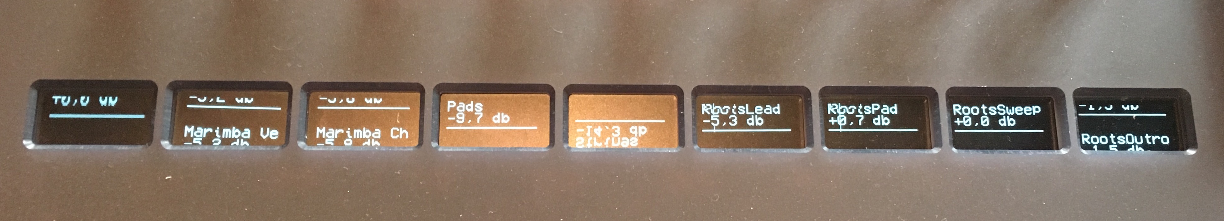
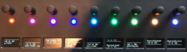
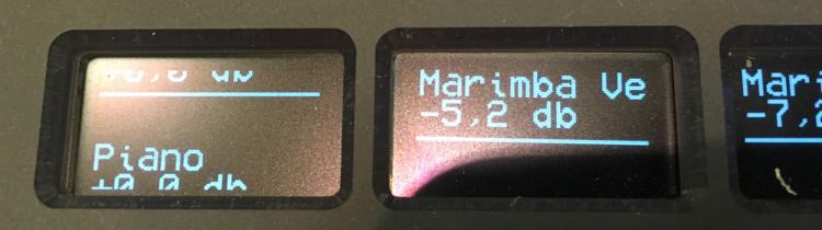
So guys.... yesterday I spent a lot of time in front of my controller. The room, where the controller is placed at the moment, has a carpet. I noticed, that I get a little shock after while walking through the room when touching metal. I was curious too see if it has an impact to my controller. So I walked through the room and after that touched the encoders, which are directly above the OLEDs. And guess what? The whole electronic became unstable: The OLEDs were freaking out (see pic above) and other illuminated buttons which are connected to the electronic went dark for a few milliseconds. I use those buttons to change the colors of my WS2812 LEDs and it seemed that some of these buttons got triggered, because the color of the LEDs were changing too. It seems that I have an ESD problem here. Is there anything I can do to protect my electronic? BTW: The caps of my encoders are made from aluminum, but they sit on a plastic shaft. So I'm not sure how the "shock" made it into the electronic. (//edit: I don't think that I can connect GND to earth on my AC input?) The first thing I'll add is the suggested cap between RST and GND. The second thing is a larger cap between VDD and VSS at the ribbon connector. For the next PCB revision I'll probably change the 10pin IDC to a 14pin / 16pin (or just add another 2pin header and use stronger wires) and add a second VDD and VSS wire for a stronger connection. Another change I'll make is adding another power supply to the unit. I thought about MeanWell LRS-50-5 which comes with 10A at 5V. I hope to get off the ripple that is inducted by the switching regulators which are working inside the case at the moment. Also for next revision maybe I can add the buffers to the PCB with Andys help... we will see ;-) Thanks for now! I'll report back.
-
It goes crazy!

-
Hey people, @Antichambre: I can't follow you regarding the decoupling cap. It should be in the right place....adding the cap to the supply-connector seems useful! Will do! I can't do too many changes at the moment to the electronic. But to try it out I killed the external power supply and power the core now via USB. As you can see I have the same problems (see pic). I hope I can do those changes we discussed here on tuesday...
-
Hey, thanks for sharing! In my design I don't have space for such a board and it would be overkill because I do not drive so many OLEDs. Anyway: I'll try Peters way first and report back! Thanks so much for your help!
-
Oh yes... I'd be really interested in this... I'm really looking for a professional / proper solution that works at anytime.... The 5V that powers the core is indeed a switching PSU running a LM2596. But I need to add an LC filter to reduce output ripple. I'll try that and the pF-cap on the clock-pin and see if it improves it... BTW: I worked with those OLEDs the whole last week without any problems! Than I moved with it to another place, and it went crazy.
-
Hi Peter, sounds great! I'll try! The only problem I have is, that this problem occurs random. It runs smooth for a while (like yesterday over 6h) or it can happen immediately (like today). Do you see a way to "force" this error? How did you check if the cap has the right value? Maybe I will add this cap not only to the last OLED but also to the 9th and see if that helps. Will do on tuesday hopefully. I don't use the onboard-regulators of the disco at all. BTW: If you say "it was good enough for me" and "it solved nearly all my problems"... what are the problems you still have to deal with? Thanks again! You saved me weekend ;-) Best, Chris
-
So to clear it up: You suggest adding a small ceramic cap between CLK and GND and see if the problem is gone? You are right... if that solves the problem, it's the easiest way.... I'll try and report back! Thanks!! //edit: I found that note: https://www.diodes.com/assets/App-Note-Files/AB023.pdf They suggest values between 50pF and 120pF if I understand it correctly: AC termination is recommended most for clock applications. An example of AC termination is when a 75? impedance is coupled with a 100pF capacitor. To allow for leakage in input impedance of the receiver, the resistor is selected to be larger than the trace impedance. To allow for rapid transition of the clock edge, the capacitor value is selected at 120pF. A higher capacitor value allows for heavier current levels to pass. However, higher capacitive values increases power dissipation. Capacitor values less than 50pF diminish the effectiveness of termination.
-
Hey guys, thank you so much for your help. @Andy: You are right: They both share the same GND. This has something to do with the LEDs. Those are WS2812B and they absolutely freak out if they have not the same GND as the core. This is why it's shared. @Peter: Yes, I'll overwork my powersupply with super-stable-low-ripple-3.3V / 5V (doesn't matter on those OLEDs... they are brighter with 5V though). So, if buffering is the solution, how would the schematic look like? Could you give an advice how such a buffer works? Is there a documentation that I can adapt to my needs? Thanks!! Best, Chris
-
I pulled the LEDs from the power and now it worked till now. Now the 10th display is "shifted".... I think I need to test your suggestion regarding connect RST to GND...
-
Meanwhile I think it maybe related to the power supply.... look at this... The LEDs are powered from a separate power supply. So the OLEDs and LEDs do not share the same.... The powersupply contains of a 19V laptop-supply which than goes into LM2956-module to break it down to 5V.
-
Also another strange thing: Yesterday I had the machine running for about 7h and it occurred at the end... today it happened already a few times.... strange...
-
Dear Andy, This should be correct. 8 CS signals come from the 595. The other two come from PC13 and PC14 of the core.
-
Dear andy thanks for the suggestions. To answer your questions: on this pcb there are 9 displays and another 6pin-connector on the very right or the pcb. A 10th display is connected through six 0.25 single wires to this 6pin connector pcb. Those have a length of about 35-40cm. In the boot loader the number of displays is x=10, y=1 I need to mention that this effect occurred on the first display as well as on the 10th. All other displays were still running fine.
-
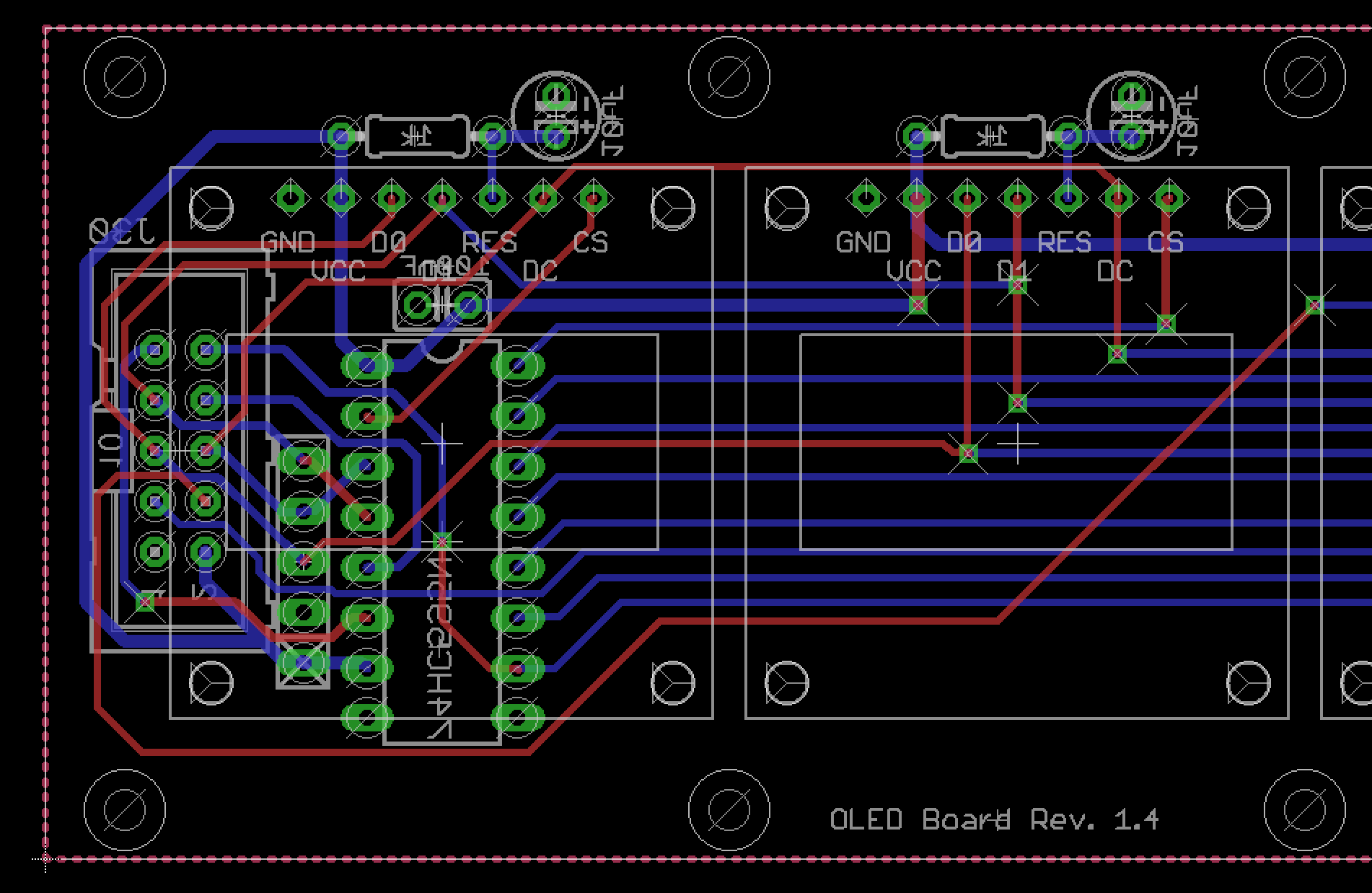
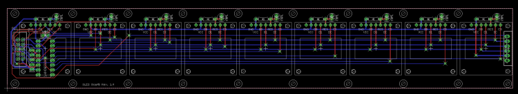
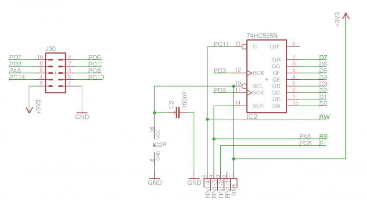
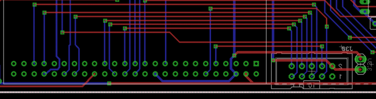
Dear Andy, thanks for the reply! I uploaded the pictures into the gallery! I designed my own core which has only the connectors on board, that I need. The core is connected through a 10cm ribbon cable to the OLEDs-PCB (there are 9 OLEDs on this PCB). The shift register, which is normally on the core PCB I've added to the OLED-PCB so I can save space on the core. The pinout of the connector you can see on the pictures: OLED-PCB schematic: OLED-PCB layout: Core-layout: Thank you for your help!

-
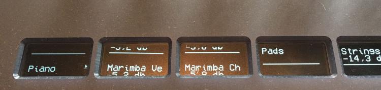
Hey people, I have some problems with my OLEDs. Technical background: The OLEDs are mounted on a PCB and powered through a stable 5V power supply (they can be powered with 3.3V or 5V). Each OLED has a 1k resistor between RST and VDD and a 10uF cap between RST and VSS. The OLEDs are triggered by NG. In NG I've added several receivers and senders, which translate sysex-streams into labels. That works very well... but! I uploaded a picture where you can see the problem. Sometimes after using the MIDIbox for a while I get those errors. I'm really not sure what the problem is. I need to powercycle the midibox, to "reset" the displays. As you can see the whole label gets moved down and it will NOT reset by sending new sysex-events. So, do you have an idea? Is it something in the firmware or is it hardware? Maybe also @TK. can help ;-) Thanks!! Best, Chris
-
Hey people, it looks like the NGR-function set_active is not working for senders and receivers. @TK.: Would you might have a look at it? Best, Chris
-
Set and control an element:ID based on the received value?
FantomXR replied to FantomXR's topic in MIDIbox NG
Sure! This might work (didn't check yet). But I thought that there might be a much simpler way which says: take the note # and activate the RGBLED with the same ID. But it looks like, that's not possible... And in the end you are right: I need to define every RGBLED anyway.... hm... alright! ;-) I'll come up with another task these days... but I need to think about it first a bit more ;-) -
Set and control an element:ID based on the received value?
FantomXR replied to FantomXR's topic in MIDIbox NG
I do not understand what you mean exactly. If "use_key_number=0", the receiver passes the velocity to the fwd-element. If it's =1 it passes the note-number. That's clear. But how do I "connect" the note-number with the corresponding ID of the RGBLED?