

FantomXR
-
Posts
1,035 -
Joined
-
Last visited
-
Days Won
22
Content Type
Profiles
Forums
Blogs
Gallery
Posts posted by FantomXR
-
-
No, the cables on the picture are not twisted. Again: Please check the link that I've posted above. There is a picture of how the cable has to be made.
-
Dear aurel33,
I already wrote you a message, that you need to twist the cable, that goes from the core to the DIO. Did you test it with a twisted cable?
Look here:
http://ucapps.de/mbhp_dio_matrix.htmland also I wrote you that you need to use straight cables, that go from the adaptor to the DIO. It will not work with a twisted cable.
-
Thanks for sharing fantomxr, one question regarding the fatar adapter, what are the BK10-03 and BK10-04 jumpers used for as it's not written on the pcb ?
For a 88 keys keyboard, do we need to solder bk10-03 + mk10-03 ?
of course not!
you have to check it with the schematic of your keybed. Normally an 88 boards need the mk10-03 and bk10-04 to be soldered.
-
I never checked out aftertouch deeply. But as far as I know you need only three of the four pins. 5V, GND and the analog input signal. Search the forum. Someone gave some great informations about it here in this thread if I remember correctly.
And the reason why you have two of those strips is that the black and white keys have separate aftertouch strips.
-
Connect the tip to 5V and the shaft via a 1k resistor to GND. Put the analog input of the AINSER right before the resistor.
5V -----/ ---- 1k-----GND
I
---> A0
BTW it doesn't matter if the tip is connected to 5V or the shaft. You can easily invert the values inside NG (should work in KB too) if the pedal works the wrong way around.
-
Just to make sure: once this board has been set up and configured it will always run stand alone, i.e. without any further PC-connection? Connect MIDI keyboard on USB, MIDI OUT to e-drum by MIDI cable, switch it on, reset it, done. Play. Retire the PC. Is it that?
Best, Michael
I'm interested in this too. I tried the USB-Host-Mode two weeks ago with two different devices and I was not able to get it working...
As far as I know the STM automatically boots into Host-Mode, if a usb-device is connected to the mini-usb. But how do I make f.e. routings? f.e. where do I set the midi ports the signal of the device is send out to. The core was not reachable via the micro-usb, if a device was attached to the mini-usb.
-
Yes, but this is not what I wanted to achieve ;-)
My goal was to set the range of the KB:1 via a button... like a "learn lowest note" and "learn highest note"....
But this is on another agenda...
-
Today I tried a bit to work with it but I was not able to get any results.
I'm missing something.
I have my keyboard:
EVENT_KB id=1 type=NoteOn chn=1 key=any use_key_number=1 range=0:127 ports=100011000000
and I know that ranges can be set via a NGR script to a fixed number. But I have absolutely no idea how to set the range based on the key that is pressed because the set_min command requires a value after the ID... I overlook something. I might be able to get it working with a lot of if-commands in the NGR. Than I would add an if-command for every key... but I don't think that this is the right solution.
I also tried to work with the MidiLearn and LearnEvent metas... but I was also not able to get it working. Any tips? Show me the part that I overlook... :) -
Hey people,
as I'm an active member of this community for quite a long time and I really appreciate the help that one gets here, I'd like to share the PCBs with you, that I've created over the last two years. I already created a wiki-entry a while ago but I think this might be overlooked and maybe I can give you some inspirations with those PCBs. The layouts are tested but there might be a few mistakes on the silkscreens. If you found out, somethings wrong, please do not hesitate to contact me. Also I didn't take time to make a clean schematic.... so this might look sometimes confusing ;-) But as I said: It's all tested and should work.
I will not share the PCBs I recreated from TKs schematics, because you can get the PCBs either at SmashTVs shop or the *.brd-layout on ucapps and I don't want to compete with Tim.
So let's start. If there is something in the layout that needs to be explained, I will add a little description to them.
In general regarding the SMD-layouts: They can be soldered by hand with a good solder iron. There is no need to have an reflow oven or similar.
1x DIN (SMD):
Description: No mounting holes due to a small size!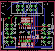
1xDIN.zip
1x DOUT (SMD):
Description: The package, that is labled with ULN2803 can be either used for of course an ULN. But the footprint fits also resistor-array (f.e. bourns 4816-series). No mounting holes due to a small size!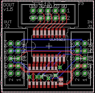
1xDOUT.zip
8x Encboard (SMD):
Description: This is an pcb that can be directly equipped with ICs and than be attached to the core without any other DIN modules. Distance between encoders: 29mm (fits the DTSM-64 distance layout (see below)).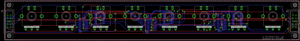
8xEncboard.zip
Fatar Adapter:
Description: This adapter can be used to connect an 76 or 88 keybed to a DIO-module. You need to solder the jumpers as needed.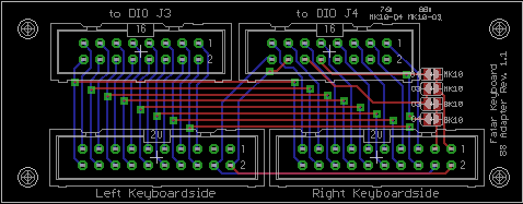
Fataradapter.zip
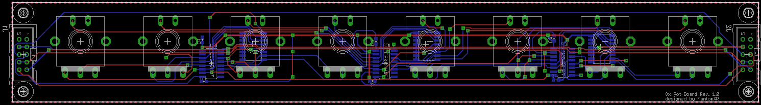
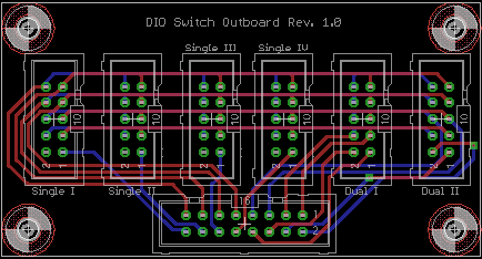
DIO-Breakout:
Description: This adapter is used to split the pins of an DIO-module into more usable pin-headers. See my switch-boards below.
DIO-Breakout.zip
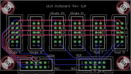
ULN Breakout:
Description: Same as DIO-Breakout.
ULN Breakout.zip
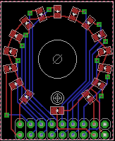
LED Ring (SMD):
Description: This LED ring is made for 0805 LEDs. Good soldering skills needed.
LEDRing.zip
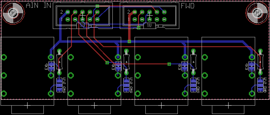
Neutrik-jack PCB:
Description: This PCB can be used to attach easily sustain- or expressionpedals to an AINSER8 module. Solder jumpers as needed and don't forget the 1k pull up resistor when using it for sustain-pedals / switches.
Neutrik.zip
OLED Breakout:
Description: The module can be directly connected to J15A/J15B of the core. You can then connect OLEDs in conjunction with the display-board directly to the core without soldering any wires.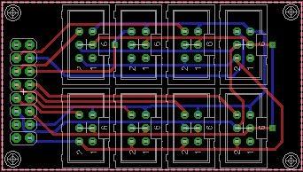
OLED Breakout.zipOLED Displayboard:
Description: You need this pcb in conjunction with the OLED Breakout above. This pcb will be soldered directly onto an OLED which you can get for good prices on ebay or aliexpress. Pay attention, that this will only work for OLEDs which have 7 pins single-header connectors.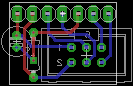
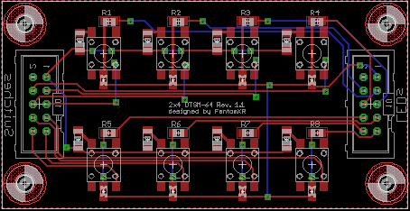
OLED Displayboard.zip2x4 DTSM-64 (SMD):
Description: You can connect this PCB directly to the DIO- / ULN-Breakout board (see above), but it should work with classic DIN/DOUT modules too. Switches are DTSM-64.
2x4DTSM.zip
8xDTSM-64 (SMD):
Description: You can connect this PCB directly to the DIO- / ULN-Breakout board (see above), but it should work with classic DIN/DOUT modules too. Switches are DTSM-64.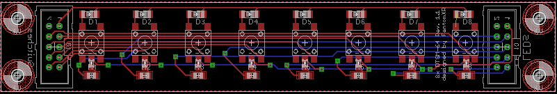
8xDTSM64.zip
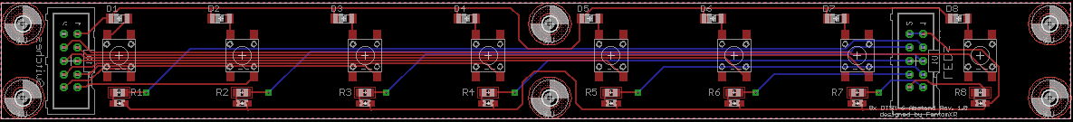
8xDTSM-64 distance (SMD):
Description: Distance between the switches: 29mm. You can connect this PCB directly to the DIO- / ULN-Breakout board (see above), but it should work with classic DIN/DOUT modules too. Switches are DTSM-64.
8xDTSM_distance.zip
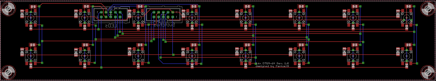
16xDTSM-64 (SMD):
Description: You can connect this PCB directly to the DIO- / ULN-Breakout board (see above). Won't work with classic DIN/DOUT modules. Switches are DTSM-64. Distance: 29mm.
16xDTSM.zipThat's it for now. This list will be updated if there are any news.
-
 1
1
-
-
Look at this:

it's turned by 180°
-
You are right. It should work this way. I have several keybeds connected like this. You used a twisted cable for connection DIO to J8/9?
-
Hey TK,
in the past two weeks I ran pretty much into the problem, that the keys of the keybed do not react equally...some are more sensible than others and vice versa. I could go and create a velocity-map for every key but as you can guess this would be a lot of code and a lot of stuff to do.
I'd like to ask you if you think it might be possible to somehow control delay_fastest / slowest for every key instead of the whole keyboard. Or does that require a lot of changes / addons in the code?
Thanks!
-
Hmm,
I still think there's some merit in this, for example with a single PCB and 4 displays (e.g. MBCV) you could get away with 4 standoffs and simpler wiring/less POR circuitry etc.
You can of course easily adopt my breakout-board to fit four displays instead of just one.
Did you consider FPC/FFC sockets? A quick search revealed that all of these are SMT but the metal pins are more amenable to solder than the flat cable. 0.5mm pitch correct? Tricky but doable.
No, it's not 0,5mm, which is the problem. It's 0,7mm and I wasn't able to find a fitting socket.
-
Well... it would be possible. But you would need to send A LOT of MIDI messages on patch change. I had no idea yet how to get around this...
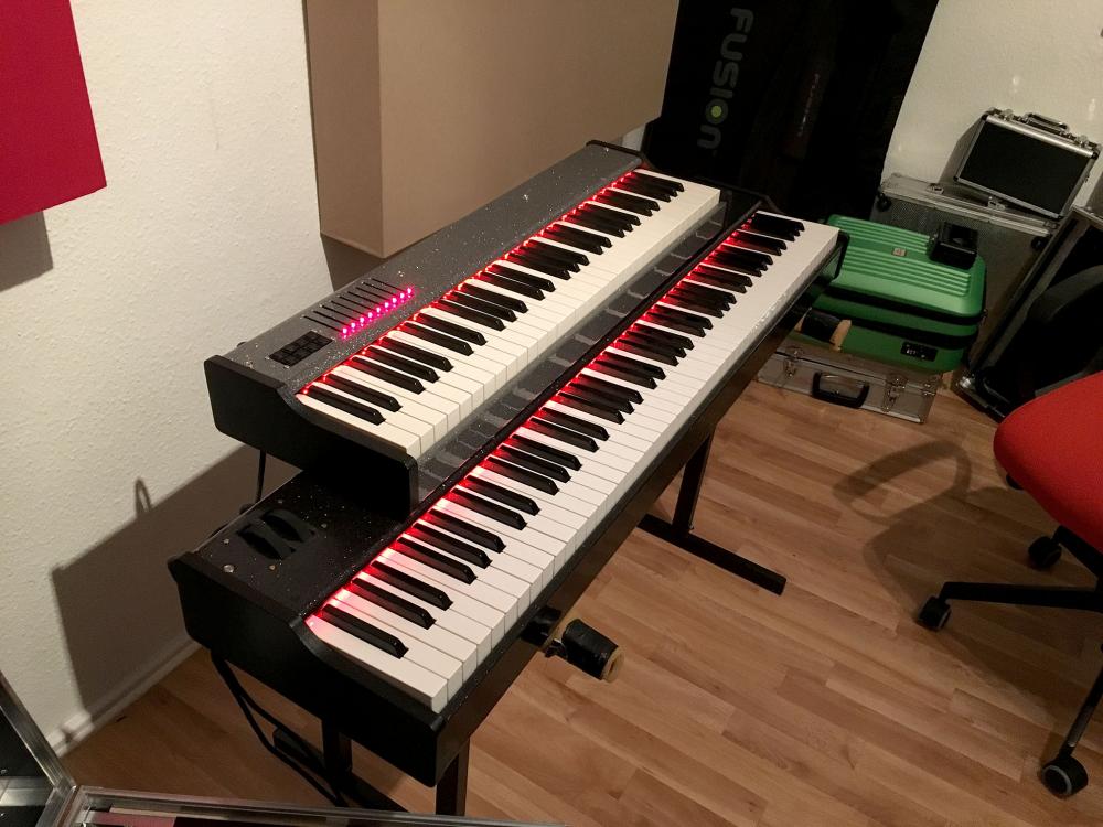
And finally: The distance between each LED is not the same as the keys... so not every key has it's LED. I have 71 LEDs on the lower board and not 88 :-) Anyway... it's already such a nice feature... I LOVE IT!! :-)
-
Thanks for making some things clear ;-)
It looks awesome... :-)
-
I did some more testing:
1.) Using a shielded cable doesn't help. I'll try to experiment with aluminium foil to shield the pots of the mod/pitchwheels
2.) The LED-strip seems to be directly connected to the AINSER-command. Create an empty NGC and put this code in:
RESET_HW
SRIO num_sr=2
now run ngr exec_meta rgbledrainbow:9:20. Now look at the speed of the LEDs changing.
Now create another NGC and paste this code:
RESET_HW
AINSER n=1
SRIO num_sr=2
The rainbow effect should still go on when you change between those two NGC files. But you an see that the speed differs. Is this meant to be like this?
And also changing the number of num_sr=x will change the speed drastically.
-
Hey people,
maybe this is just an easy thing... but I have a problem when I connect two midiboxes to my computer (Windows). I'm just able to access one MIDIbox only via MIOS Studio. The other one appears in the MIDI-ports list and I can click it and it seems, that MIOS Studio also connects to it. But when I switch to the file browser I see the exactly same content as on the MIDIbox before. Both MIDIboxes run NG.
Is there anything one could do? I tried to change the device-ID of one of the controllers... also without success.
Any help? :-)
Thanks,
Chris -
And btw: Is there a chance so control the LEDs with the internal MIDI clock so it can act like an visual metronome? :-)
//edit: just discovered another "bug". When I set the rainbow on and run after that RGBLedClearAll not always all LEDs will go off. Sometimes (random) a few of them are still on in different colors (no rainbow effect). I'd need to use the command twice in this case to shut off all LEDs. :)
//edit2: And finally I recommend to use a shielded cable which goes from the output of J4B to the strip. I didn't use one and I wonder why my pitchwheel outputs values all the time. I found out that it behaves normal when I disconnect J4B. I'll try the shielded cable tomorrow.
-
Dear TK,
there is a little error message, which the terminal outputs as soon as I start the midibox:
[15857.189] AUTOLOAD 'DEFAULT'
[15857.189] [MBNG_LCD] no response from CLCD #1.1
[15857.189] [MBNG_LCD] no response from CLCD #2.1
[15857.213] [MBNG_FILE_L:23] ERROR: 'EVENT std_rgbled': label too long, should be 8 chars maximum!
[15857.214] [MBNG_FILE_L] 1 error has been found while generating the .BIN file - please fix DEFAULT.NGL!
[15857.223] [MBNG_FILE_S] snapshot #0 not stored in /DEFAULT.NGS yet
[15857.223] Patch 'DEFAULT' loaded from SD Card!
[15857.227] [MBNG_FILE_R] /DEFAULT.NGR (optional run script) not foundDo you get the same message?
-
Works perfectly! :-)
-
Thanks for the explanation! I'll do that ;-) But I'll need a few days to complete the build!
-
As long as you don't enable all LEDs with full brightness, the power consumption is much lower, so that you could supply the strip via J4B
Ah, thanks! Today I found a power supply, that has 2A and I connected it to a 2m strip with 60 LEDs / m. Every LED worked also if I set them to full white. But I didn't control it with STM but with another RGB controller. I expected that not all LEDs will work with 2A... do you think that the LEDs will be even brighter with a more powerful power supply? They were already very bright ;-)
The meta description says "LED 1-64", because in the driver only 64 LEDs are enabled (each LED consumes 48 bytes, therefore I'm careful).
However, if somebody wants to drive more than 64 LEDs, I could increase the number.My strip has 120 LEDs but I will cut it to fit an 88 keyboard. So it will be around 90 LEDs. Will then only 64 LEDs work?
Thanks! ;-) Can't wait to see it in action.
-
Whooohoooo! Awesome!!!! :-)
My strip came today but I don't have a power supply that is strong enough.
So, in theory every LED could be adressed individually... right? The meta only says LED 1-64... that's why I ask.Thanks TK!
-
I finally found the problem... there was a short on the EncoderPCB... now everything works fine :-)


Debugging my core STM32f4 + diomatrix + fatar keybed
in Testing/Troubleshooting
Posted · Edited by FantomXR
When I created the PCBs I didn't put any attention on the notches of the sockets. So the orientation is random.
And again: You need to twist the cable. Why do you use still a straight cable (last picture you posted)?!? TK gave also exact informations...
Anyway... it seems that you need a more in depth-explanation. Here it is and forget about the cable relief for now:
1.) Put the core and the DIO on a table
2.) Place the DIO to the right of the Core so that J8/9 and the input of the DIO face each other
3.) Take a 10pin ribbon cable, which is about 10cm long
4.) Put an IDC connector on the left side of the cable with the notch facing the core (red cable is on the top)
5.) Turn the cable by 180°
6.) Put an IDC connector on the right side of the cable with the notch facing the left-border of the DIO-PCB (red cable is on the bottom).
7.) Connect the core with the DIO and it should work.
8.) Use STRAIGHT cables for connecting the adaptor to the DIO and NOT twisted cables (like you did in the pictures above).