

FantomXR
-
Posts
1,035 -
Joined
-
Last visited
-
Days Won
22
Content Type
Profiles
Forums
Blogs
Gallery
Posts posted by FantomXR
-
-
Thanks for the reply! Then I will try that tomorrow...
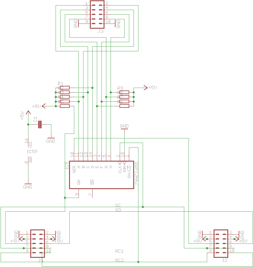
Anyway... here are the files. The 2x DOUT is not equipped with ULN but with 220Ohm resistors.


-
Hey people,
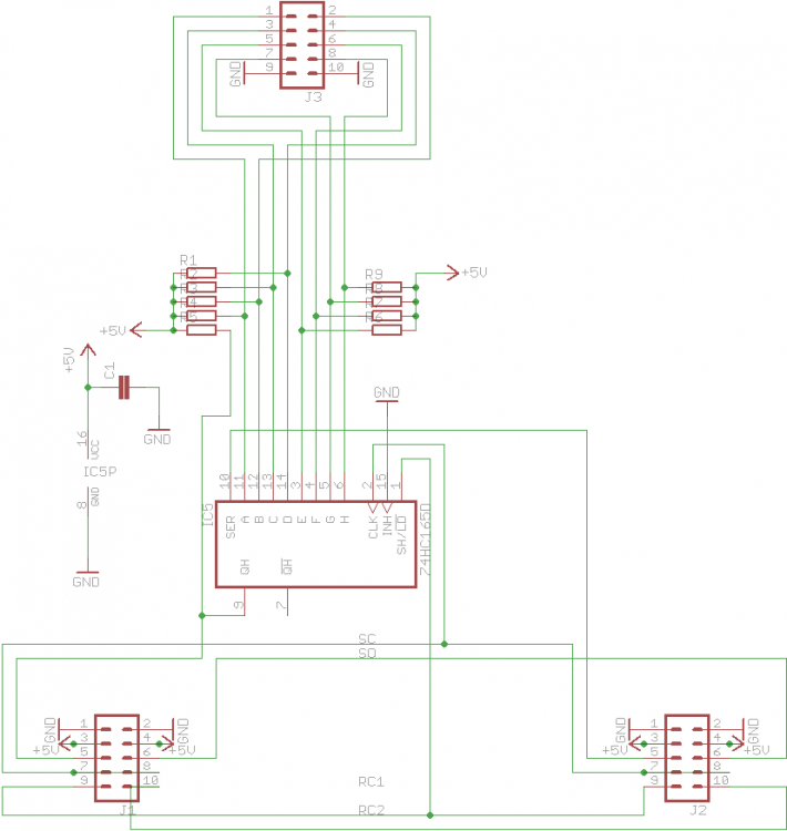
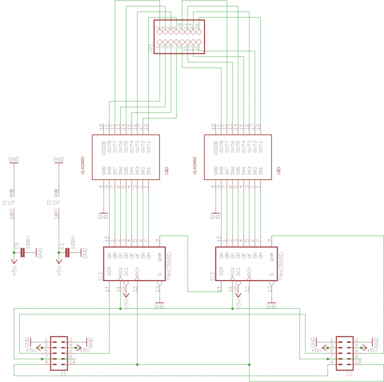
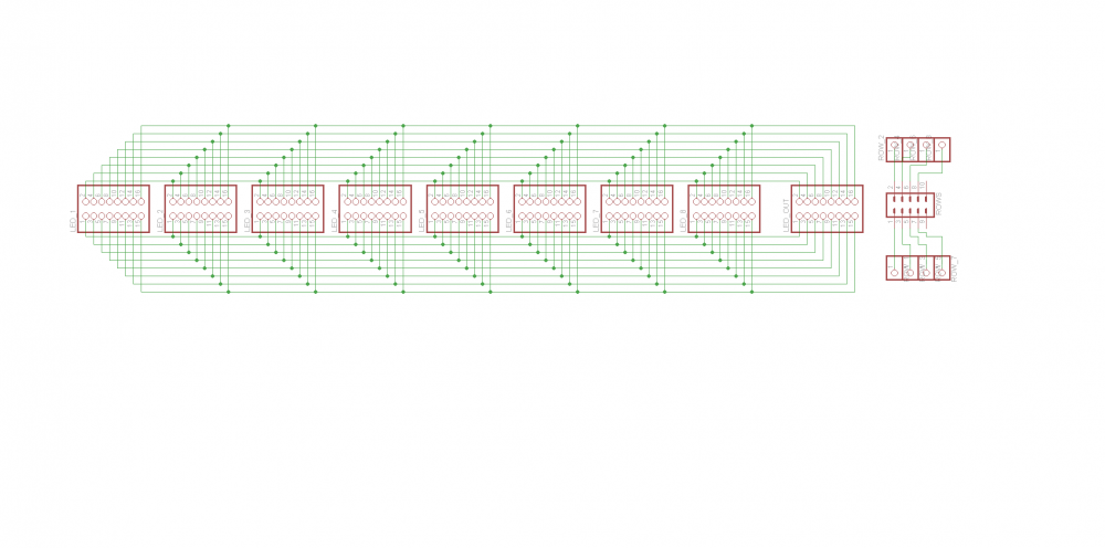
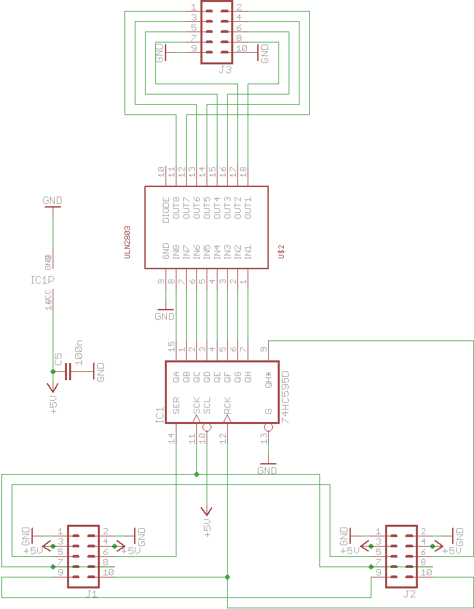
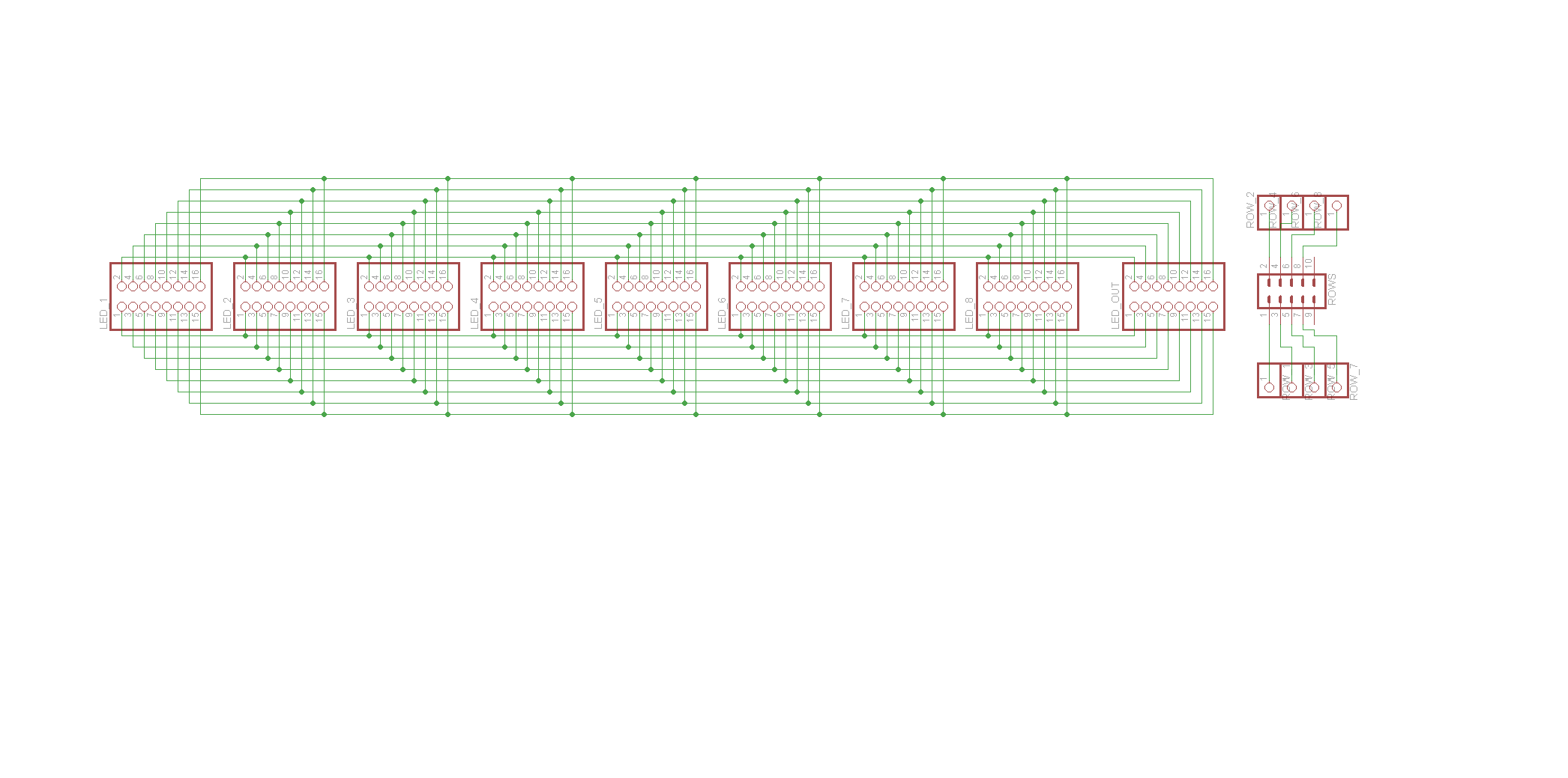
I have some trouble with self designed PCBs. I have three DOUT SRs which power 8 LED rings perfectly. The first SR is equipped with a ULN2803 as driver. This works as expected.
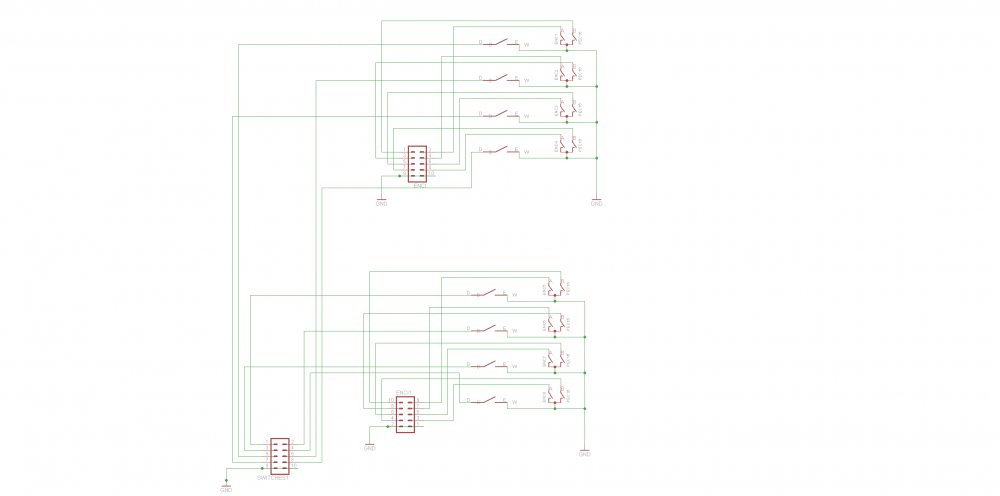
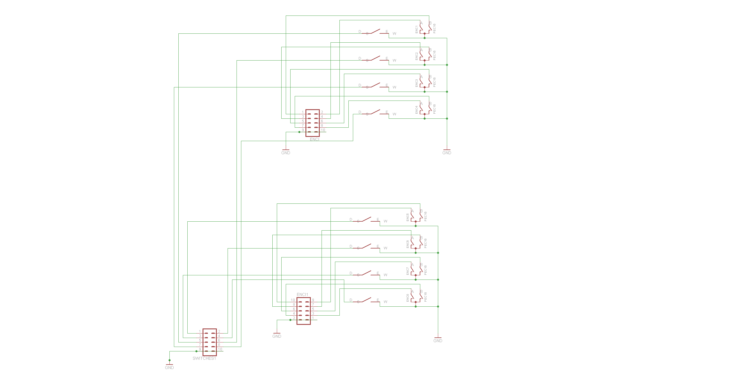
Now I want to connect the encoders and switches to it. I add a DIN-PCB but as soon as I connect the 10pin IDC of the switches to the DIN, the LED-rings go off. There is just one LED, that is still bright. If I disconnect the ULN-PCB, nothing changes. Still this LED is on.BTW: The switches are working! If I set debug modus on I see that the PCB works as expected... just that the LED-rings go off is really not clear for me.
I'll add the schematics here later on.
Just a question: Are RC1 and RC2 are supposed to be soldered together like in this schematic:
http://ucapps.de/mbhp/mbhp_dinx4_r5.pdfI have them seperated (DOUT got RC1, DIN RC2).
Maybe somebody has a hint for me?
Thanks,
Chris -
Whoopwhoop! I'm very curious about it ... I also just ordered such a strip (2m but I just need 1,30m). It should be here tomorrow. I didn't plan to control it with the MIDIbox... but if it would be possible..... awesome...
But: Keep in mind that those strips draw a lot of current. In purewhite they draw 60mA each which makes 3,6A per meter with 60 LEDs. So be sure your power supply is sufficient. :)
-
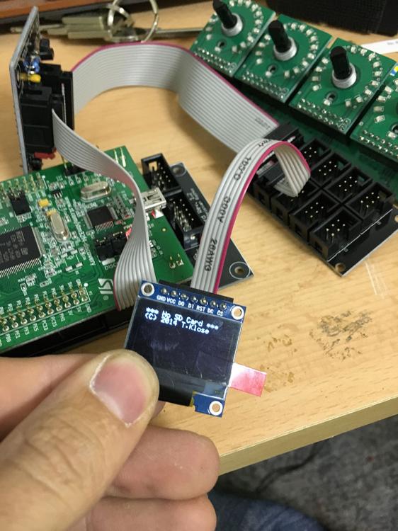
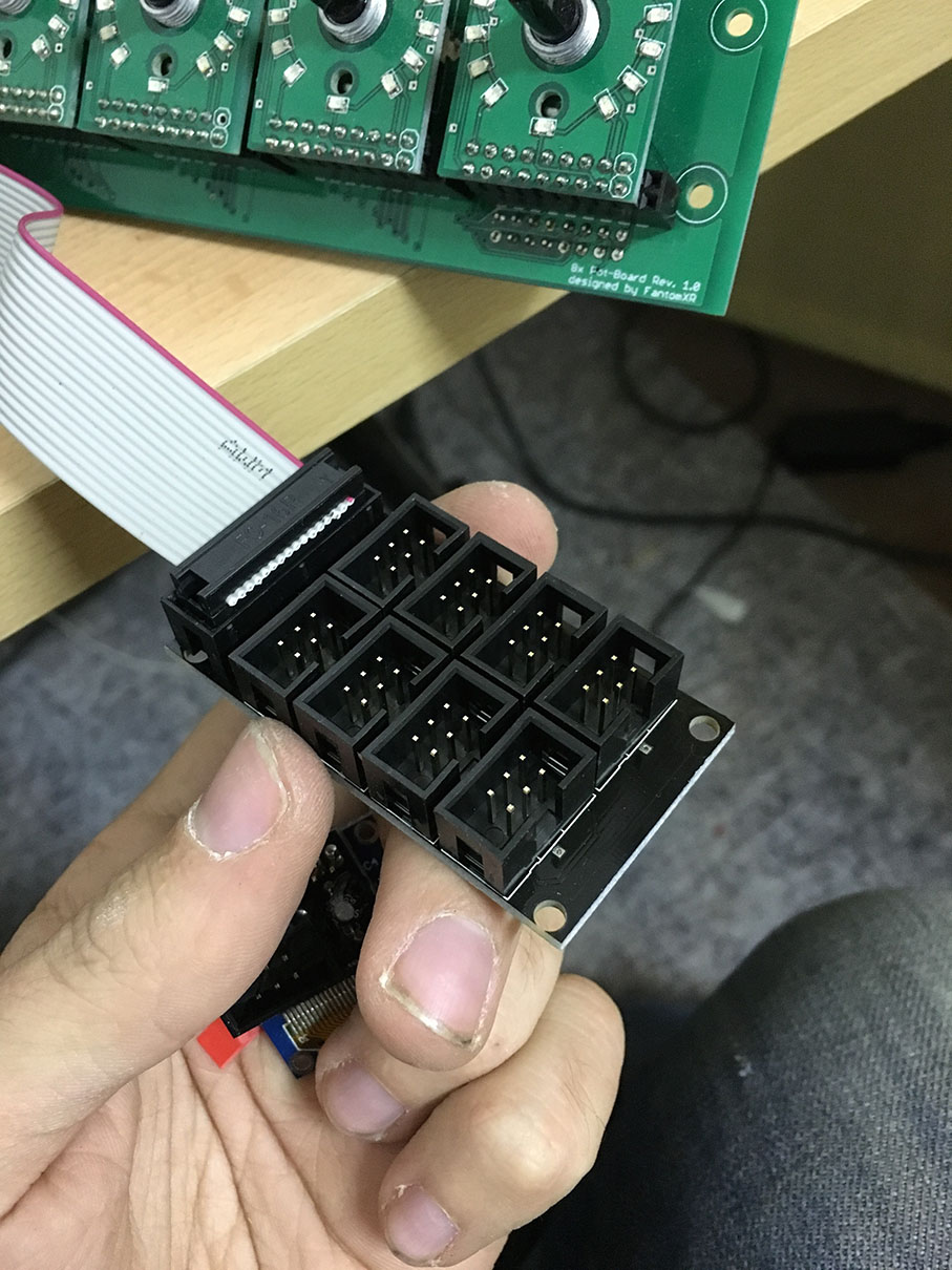
Interesting approach, what is the intermediate board between the Core and IDC6 connectors?
The core is designed by myself and normaly has no parts for LCDs on it. The intermediate board contains all parts for the LCDs (J15A/B, 74HC595, potentiometer, etc.). This is because I wanted the core to be as small as possible and I don't need displays for every build :)
-
Did you tried to disconnect the displays (J15A/B) for now and only use J8/9 for testing?
-
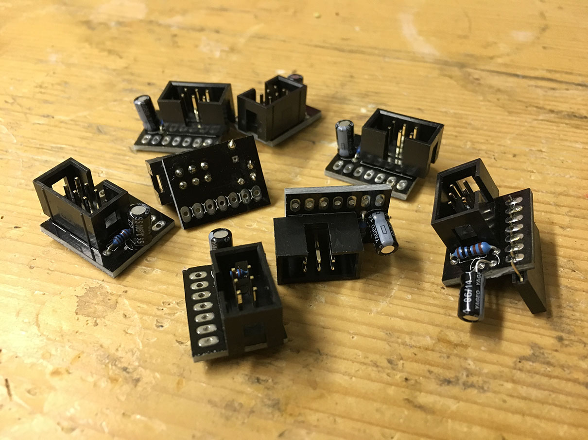
Okay... I kicked this idea. It's really too much work to get this working.
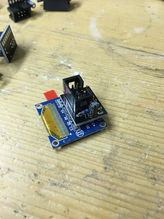
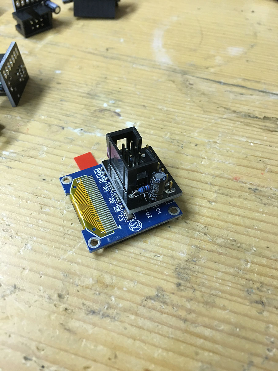
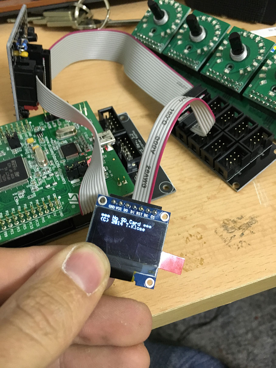
So I created something else. This is a simple breakout-board, which can be used with the core directly (pay attention of the voltage-selector). Every output of this breakout goes to another little PCB, that is stacked directly behind the OLED. This PCB contains a resistor and a cap... currently THT, but will be SMD in the next version I think.
OLED_Breakout_Displayboard.brd
OLED_Breakout_Displayboard.sch


-
Dear TK,
thanks for the conclusion.
Maybe 4 or 5 brightness levels are enough to give a bit of a fade-effect. I will check that with some of my led-rings. But I'm not sure how to program that into the NGR...
Thanks!
-
Good question! It's hard to see. I think it's about 6.
Didn't know that dimming of LED-rings is already possible. I need to check it out.
Thanks!
-
Hey people,
another question!
Today I had the MIDI fighter twister in my hands. It's a 4x4 encoder box with LED rings. It's a great USB controller... you should check it out.Anyway: When I turned an encoder I realized that the LEDs of the ring are dimmed... so they fade slowly into full brightness depending on the value. As far as I know the LEDs on MIDIbox are just going on and off. But the fades are quite fancy ;-) No big thing but I just want to ask, if this might be able in the future with MIDIbox as well ;-)
Thanks,
Chris -
Great! I'll wait for it then ;-)
-
Hey people,
inspired by another thread I'd like to create a pcb which has 3 RGB LEDs (or 9 single LEDs) on it. This PCB could be stacked on top of a encoder and illuminate it. I could cnc mill the caps for it by myself.
My question is now if it's possible to wire each color in series (so, all blue, all red and all green LEDs) or if the current and / or voltage provided by a DOUT (maybe with ULN installed) is not sufficient to light all three LEDs.The reason for this is, that it would be less programming because I only would need to add one string for each color in the NGC instead of three strings. Also it would be less wiring. There is no need to access the LEDs individually.
Thanks!
Chris -
Dear TK,
awesome! But the keypad was working flawlessly before anyway :-)
-
Hey Thorsten,
do you have any usecase-examples for inspiration? :)
-
Hey!
I just want to grab this out again. Maybe TK is able to give us a quick "yes" or "no" on this topic :-)
Here is another distributor of those displays:
http://www.wellbuying.com.tw/UP_pdf/PS007.pdf -
You use an LPC-core? Is that right?
And what do you mean by distribution-board?
BTW: Which kind of buttons do you use? They look great. -
Maybe you could provide a few pictures of the board which contains the switches, LEDs and stuff! That might be helpful.
-
Hi Andy,
a short question if you don't mind: Where do you have the layout from (text, symbols, etc.)? I'd be interested in that :-)
-
Is it possible to get the keyboard + console on one core module? Or i need to get one module for keyboard and one module for console?
I wouldn't recommend that, because by doing this you lower the resolution of the velocity of the keyboard, because more DIN/DOUT have to be scanned.
I know that for motorized faders it will be 4x MF_NG and 2x MIDI IO, for rotary encoders will use AINSER64 and for buttons and led go with DIN/DOUT or DIO_MATRIX?
Rotary encoders are also digital. So AINSER64 is not helpful here. For normal pots you want to use AINSER but for encoders you'll need to go with DIN-modules.
-
@norbim1: Which values do you use for SRIO num_sr= and debounce-cycle?
-
I discovered a bug in NG! Here is an excerpt of my NGC:
EVENT_KB id=1 hw_id=1 type=NoteOn chn=4 key=any use_key_number=1 range=59:127 kb_velocity_map=map1 bank=9
EVENT_KB id=2 hw_id=2 type=NoteOn chn=4 key=any use_key_number=1 range=0:58 kb_velocity_map=map2 bank=9EVENT_KB id=4 hw_id=2 type=NoteOn chn=2 key=any use_key_number=1 range=0:58 kb_velocity_map=map2 bank=9
EVENT_KB id=3 hw_id=1 type=NoteOn chn=2 key=any use_key_number=1 range=59:127 kb_velocity_map=map1 bank=9And here the NGR:
if (id)BUTTON:17 != 0
set_active (id)KB:1 1
set_active (id)KB:2 1
else
if (id)BUTTON:17 == 0
set_active (id)KB:1 0
set_active (id)KB:2 0
exit
endifif (id)BUTTON:18 != 0
set_active (id)KB:3 1
set_active (id)KB:4 1
else
if (id)BUTTON:18 == 0
set_active (id)KB:3 0
set_active (id)KB:4 0
exit
endifWhat I try to do is, to activate different channels on the keyboard. If I press BUTTON:17 Chn. 4 should be active and if I press BUTTON:18 also the keyboard should send on two channels (f.e. layersounds).
What happens now is that I can set the keyboard with BUTTON:17 to chn.4 without problems. But if I press BUTTON:18 nothing happens. But the strange thing is: If I now delete the whole "BUTTON:17"-part in the NGR file and try again, it works also with BUTTON:18 to set the chn. to 2.I set the debug messages on and with the code I posted it says, that there is no event assigned to hw_id when trying to use BUTTON:18.
So it seems that there are some problems with the ID-handling. If you need more informations about the problem, just let me know! Thanks!
BTW: Maybe there is an easier way to activate multiple channels on the keyboard? -
Okay! Thanks for the code! This is definitely better than before :-)
maybe TK will spend a bit time on this and can improve the app if we kindly ask him ;-)
-
Sorry I cant upload at the moment to my playground, but attached the diff. I modified the keyboard.c only in modules/keyboard. Here is my keyboard spec from the NGC file:
# keyboard configuration
KEYBOARD n=1 rows=10 dout_sr1=1 dout_sr2=2 din_sr1=1 din_sr2=2 din_inverted=1 break_inverted=1 din_key_offset=32 scan_velocity=1 scan_optimized=0 note_offset=0 make_debounced=1 delay_fastest=20 delay_fastest_black_keys=0 delay_slowest=500
Hope this helps.Norbim
Hey!
I checked that and compiled it. I have the problem that no Note Off is send when I release a key. Any suggestions?//edit: Okay. I did "set kb 1 release_velocity on" and it works ;) Thank you very much! I wonder if I can disable the release-velocity because I don't use it. But like I said. If I switch it off, there will be no note-offs generated :(
Ah! Now I understand. There are two options:1.) Set release-velocity on, set make-debounced off: High velocity-resolution but sometimes notes will send a velocity value of 1 when pressed (even when it's pressed much harder). This behaviour is random!
2.) Set release-velocity off, set make-debounced on: Lower velocity-resolution, but all notes play like they should. -
Hey,
thanks for the file! I'll try to compile the app tomorrow!
I'll keep you posted.
Best,
Chris -
Hi Chris,
I built a custom keyboard with inverted diodes, and had the same issue in NG. The solution was a massive rewriting on the nlate mentioned debounce processing code. It works now perfectly without any stacking notes. I will upload my modified routines to the playground as I get close to my PC.
Norbim
This sounds awesome!! Thanks!
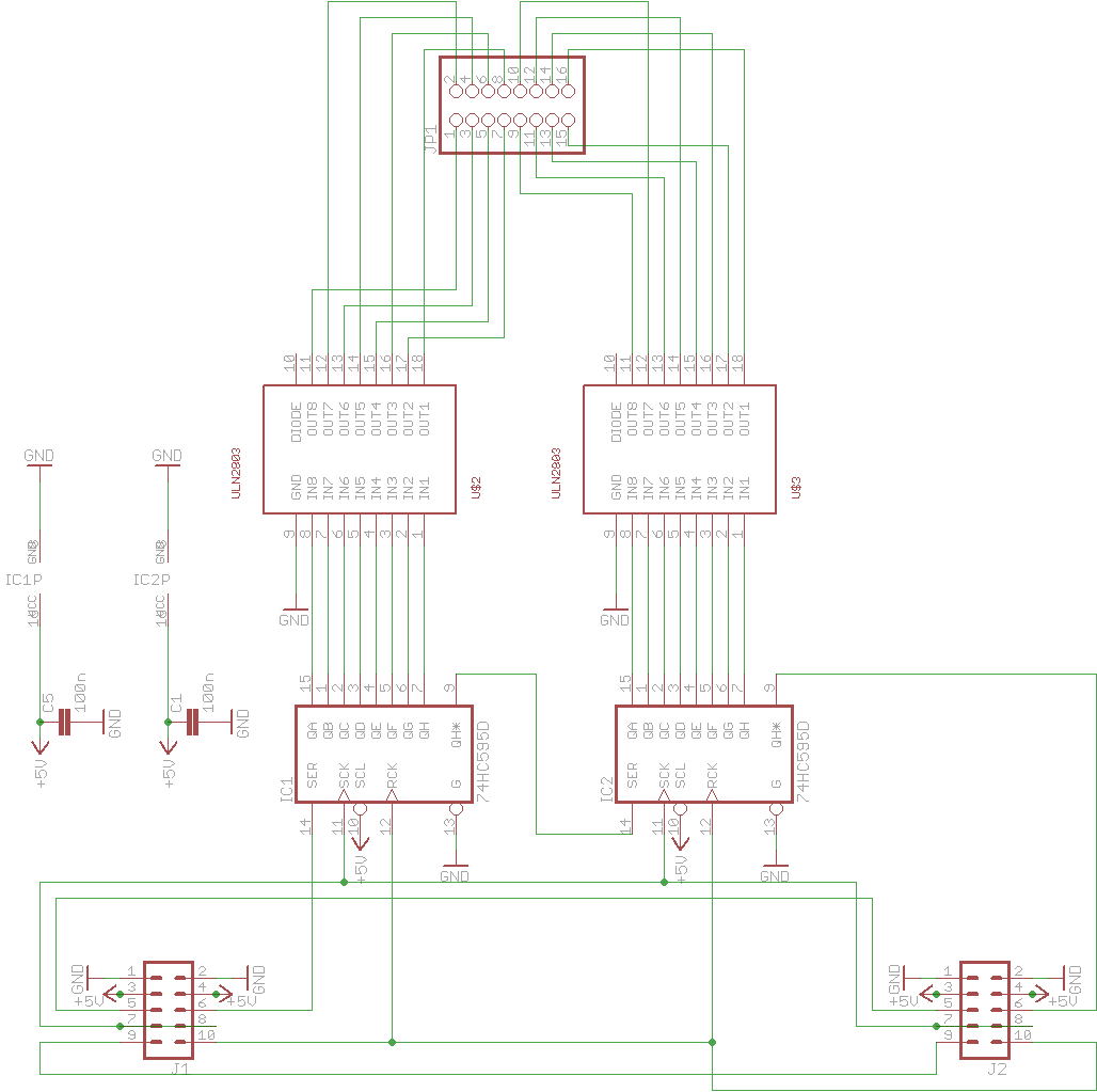
Correct connections RC1 / RC2
in MIDIbox NG
Posted
I checked now with original Midibox PCBs... same problem. So it seems there is a mistake in the encoder-PCB... but I don't see it...