novski
-
Posts
460 -
Joined
-
Last visited
-
Days Won
5
Content Type
Profiles
Forums
Blogs
Gallery
Everything posted by novski
-

Alternative to LED encoder rings: illuminated red-green encoders?
novski replied to latigid on's topic in Design Concepts
Hi I made my 8Enc PCB arround that Encoder. Its quite interresting. Then a year later i desided to make a Matrix modul and a encoder mounting pcb. Its not yet on Github because i was to busy and still waiting for the big sister with ledring to arrive but you are welcome to use it... The parts laks documentation as well because of time but im working on it... Have a look: http://www.vlrlab.com/home/29-bourns-rgb-encoder-pcb.html Im mot able to ship cheep because everything in switzerland is so expensive, as well as the parts.. I buy them for almost double the price that sparkfun sells them from the supplyers in switzerland... If you have any question regarding them please fell free to contact me or have a look into the schematics of 8enc on Github. Best Regards, novski -
Hi Romain Did you find the uCApps link? http://ucapps.de/mbhp_usb_gm5.html best regards, novski
-
Part List conversion for American buyers (Mouser)?
novski replied to kyleivanblake's topic in MIDIbox NG
Not to mention the different rates that europeans pay for a package to usa. Its really cheap to ship TO europe but not FROM europe.... -
Part List conversion for American buyers (Mouser)?
novski replied to kyleivanblake's topic in MIDIbox NG
You can find several Parts on my Fadercore Wikipages: http://www.midibox.org/dokuwiki/doku.php?id=fadercore_-_fadermodule_for_audio_daw Sometime it helps to find the right cathegory faster... Regards, novski -
Have a look to this almost at the bottom you can find the chapter MF... http://ucapps.de/midibox_ng_manual_ngc.html
-
Hi Yes, MF_NG can be connected to a chain of 4 Modules. It workes by connecting the midi out port to the in port of the second module and so on. But befor you will have to connect it with your Computer and set the Modul 1-3 to the Link through mode with Mios Studio MF Tool. The last Module you will have to set as End Point Module. Also the Protocol has to be set Right. Take a read in the Manual of http://ucapps.de/midibox_ng_manual.html Best Regards Ivan
-
Hi Yes right you can make your own J8/9. The SD card is used for the App. So you will have to load the Bootloader through the miniUSB connector. Then you will have to Download MIOS Studio to your PC/MAC and upload the MIOS system trough the microUSB to the controller. The Apps store the Controlling script on the SD card to save the space inside the chip... After that you need to Upload the App you whant to play with. Its like a PC where first is the bios then the OS like Windows or Linux and to do anything you will likely start a Program like an Texteditor that saves the file to a SD card... (Maybe) There is a walktrough tutorial on the ucapps site. Just click on the STM32 Core link. Best regards Novski
-
Just read the ucapps site. There you also find the link to the midibox-shop.com that sells a breakout board...
-
Did you look in to the ucapps.de site? Seams to me that thats not compatible to the standards set by midibox. You will have to get a special sd card adapter and make a adapter to get a J8/9 as well.
-
I think that you don't have to care about the measurement type because your DAW will send the Midi-Meterdata acording to your settings in the DAW it self. So if you have a Analog Needle Meter (generally called VU-Meter) you only have to convert the Midi Value in to the Voltage needed by your Needle. And if you like to have LEDs (digital Meter) you can just make a LED-Matrix. I have done that for me and created also supporting PCBs. http://www.midibox.org/dokuwiki/doku.php?id=fadercore_-_vlr-8x16ledmeter Best regards Novski
-
I still can't follow your topix here. Do you have digital or analog VU meters?
-
Hi Frederic You don't need the breakeout. Its just a sort of Basis for connecting different Modules. You can try to extract the pins you need with this schematic (http://ucapps.de/midibox_ng_manual_lcd.html) and the schematic of the Core. My pcb is made to fit 0.96" oleds. What size are you targeting? Best regards Novski
-
Hi Fredric Well the MB_NG is a Software you can find in the Download section of ucapps.de. What you need to get that wonderfull software running is just the newest core. The STM32F407. If you are interessted in the board i made to attach 8 OLEDs seamless have a look to vlrlab.com. The dokumentation to the VLR_8oDisp is in work and will be available soon. To those displays from taobao you have to check. It seams to me that there is a missing Enable line. And the Driver is not the same (SSD1106 instead of SSD1306) Best Regards, novski
-
Hi FredericSweden There exists a way of configuring a MB_NG with a chain of 32 OLEDs it is described in the Wiki here: http://www.midibox.org/dokuwiki/doku.php?id=fadercore_-_fadermodule_for_audio_daw And John E. Finster is a Username of a guy who already finished his setup and made a nice Tutorial about it in the Wiki as well: http://www.midibox.org/dokuwiki/doku.php?id=john_e._finster Best Regards Novski
-
<blockquote class='ipsBlockquote'data-author="latigid on" data-cid="169947" data-time="1430424581"><p> Heh, nothing too fancy!<br /> <br /> I'm still learning PCB design, but one rule of thumb is that you shouldn't have breaks in your ground plane where signals run across. If they go over a slot the return current has to take the long way around. Probably complete overkill unless you're getting into the MHz range, but I figure why not if it can be done without too much fuss.<br /> <br /> <span rel='lightbox'><img src='http://midibox.org/forums/uploads/med_gallery_5453_5_127181.png' alt='Posted Image' class='bbc_img' /></span><br /> <br /> The blue is a keepout zone as measured from the Core r4,</p></blockquote> Also have a look to the outlines of a 8pin socket for the optocoupler IC2. It seams to me that the resistors arround it are to near.... And maybe C4 will be hard to mount as well. Best regards, novski
-
Well thats certanly possible but also not easy to do if you are looking for a Motorized Fader. I can imagine some Magnetical Cap thats been moved throu a Motor from the other side of the Frontplane but still it would be a mechanical part and i think its more reliable to directly take a Fader with mechanical tracking then. Especialy in thaughts of my 5 fingers mostly stabalizing an laying on top of the next two tracks to fade gently the one my pointing finger is moving... 😄 But maybe for DJs with just a couple of Faders it would be more interessant, also because a DJ more or less does more Manualy than Automated. Best Regards, Novski
-
Hi FantomXR Yes there is also a Midi-Router inside MIOS so you are able to route the Hosts you have to different ports as well... What application are you running? you can type help in the MIOS "send command" line to get some help and the momentary status of your router...
-
As far as i know thats not possible. Because a Midi Port is quite similar to a Serial Port, and there for sure its not possible. But most of the core run more than one Midi IN/OUT ports. The only core known by me that has just one is the old 8 bit PIC18Fxxxx. What OS are you working with? best regards, novski
-
Hi The most advanced Fader builder is penny & gilles. Like this: http://www.cw-industrialgroup.com/Products/Faders/Linear-Motorised-Fader-PGFM3200.aspx But thats an expensive part. So the most used one is the Alps : http://www.alps.com/prod/info/E/HTML/Potentiometer/SlidePotentiometers/RSN1M/RSA0N11M9A0K.html They also produce pcb mountable ones. What you need to know is that midibox MF_NG is working with linear Faders. If you don't know about midibox have a look to ucapps.de and the shop selling the DIY kits midibox-shop.com Best regards Novski
-
Hi rosch Seams like the Kits (pcb & parts) are still available. Not so the pcb alone. I think i will make the PCB by myself. Did you buy the Kit? Best regards Novski
-
Oh yeh. Now i understand the datasheet reference desing as well! Thanks for pointing that out!
-
Hi FantomXR Thank you for the reply. I think i understand now. What happened is i connected the DOUT selection rows wrong. The first is the last and so on. Because i didn't have enough Headers laying around i tested just with two and didn't recognize my fault because i didn't see the last selection row glow when i tried to light up the first... Now because i got the Meters light up with Inverted=0 but not with Inverted=2 i was searching for a failure always with a inverse working circuit. Have to redo my board or live with the inversed Matrix number... Best Regards Novski
-
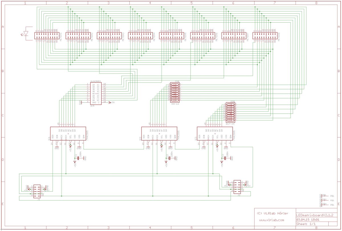
Hi Im currently Testing a 8x16 LED Matrix. I can't find out why all the rows are lighting up simultaneously. the .NGC config is a simple test: RESET_HW LCD "%C" LCD "@(1:1:1)OLED1" # Test D-OUT LEDmatrix board # Matrix control by a Encoder connected to DIN Board on Pin D0/D1 ENC n=1 sr=1 pins=6:7 type=detented2 DOUT_MATRIX n=1 rows=16 inverted=0 inverted_row=0 sr_dout_sel1=1 sr_dout_r1=2 sr_dout_r2=3 EVENT_ENC id= 1 fwd_id=LED_MATRIX:1 type=CC chn= 1 cc= 24 lcd_pos=1:1:2 label="^std_enc" LED_MATRIX_PATTERN=1 LED_MATRIX_PATTERN n= 1 pos= 0 pattern=0000000000000000 LED_MATRIX_PATTERN n= 1 pos= 1 pattern=1000000000000000 LED_MATRIX_PATTERN n= 1 pos= 2 pattern=1100000000000000 LED_MATRIX_PATTERN n= 1 pos= 3 pattern=1110000000000000 LED_MATRIX_PATTERN n= 1 pos= 4 pattern=1111000000000000 LED_MATRIX_PATTERN n= 1 pos= 5 pattern=1111100000000000 LED_MATRIX_PATTERN n= 1 pos= 6 pattern=1111110000000000 LED_MATRIX_PATTERN n= 1 pos= 7 pattern=1111111000000000 LED_MATRIX_PATTERN n= 1 pos= M pattern=1111111100000000 LED_MATRIX_PATTERN n= 1 pos= 8 pattern=1111111110000000 LED_MATRIX_PATTERN n= 1 pos= 9 pattern=1111111111000000 LED_MATRIX_PATTERN n= 1 pos=10 pattern=1111111111100000 LED_MATRIX_PATTERN n= 1 pos=11 pattern=1111111111110000 LED_MATRIX_PATTERN n= 1 pos=12 pattern=1111111111111000 LED_MATRIX_PATTERN n= 1 pos=13 pattern=1111111111111100 LED_MATRIX_PATTERN n= 1 pos=14 pattern=1111111111111110 LED_MATRIX_PATTERN n= 1 pos=15 pattern=1111111111111111 My diagram of the circuit shows the DOUTs that are connected to LED boards where all the Cathodes are parallel and the Anodes connected directly to the DOUT 2-3 as the example on the top left corner shows. What am i doing wrong here? Thanks for some help. Best Regards Novski
-
Hi The AOUT is sold out on midibox-shop.com Is there a update expected on that module? Best Regards Novski
-
Don't worry - be happy!