novski
-
Posts
460 -
Joined
-
Last visited
-
Days Won
5
Content Type
Profiles
Forums
Blogs
Gallery
Everything posted by novski
-
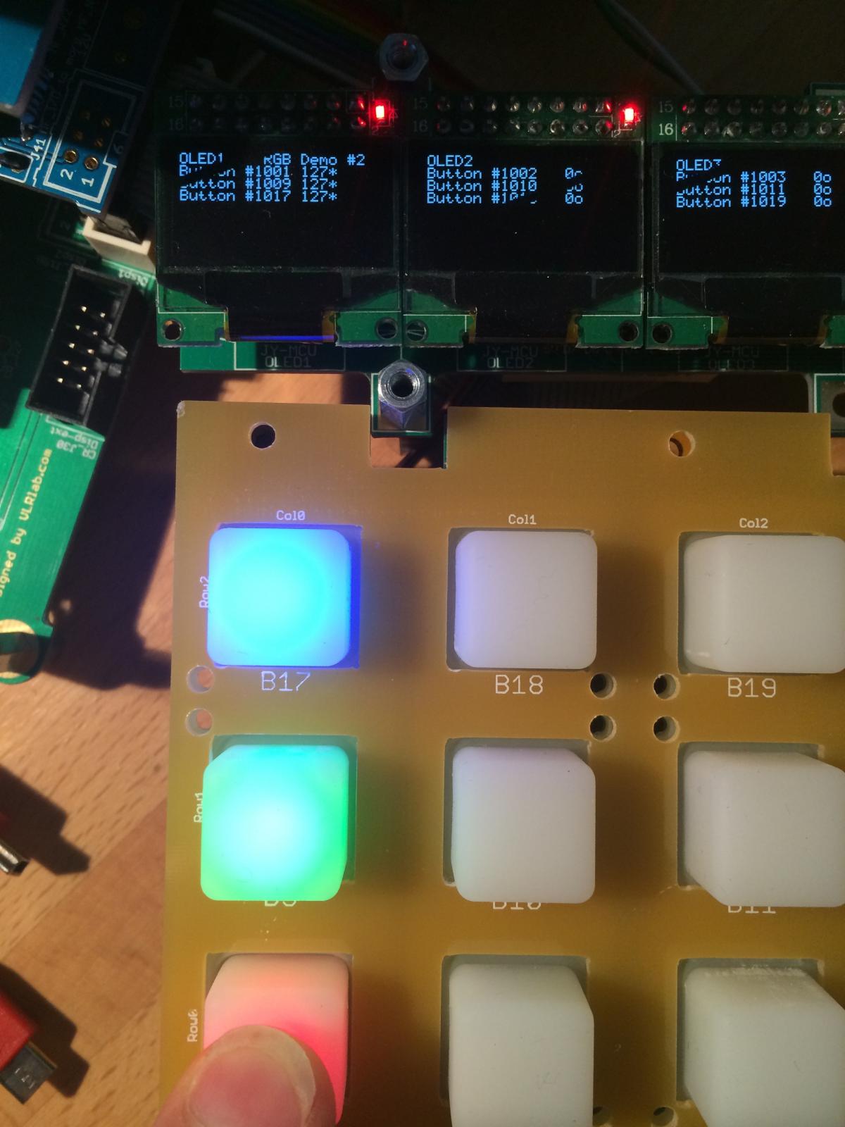
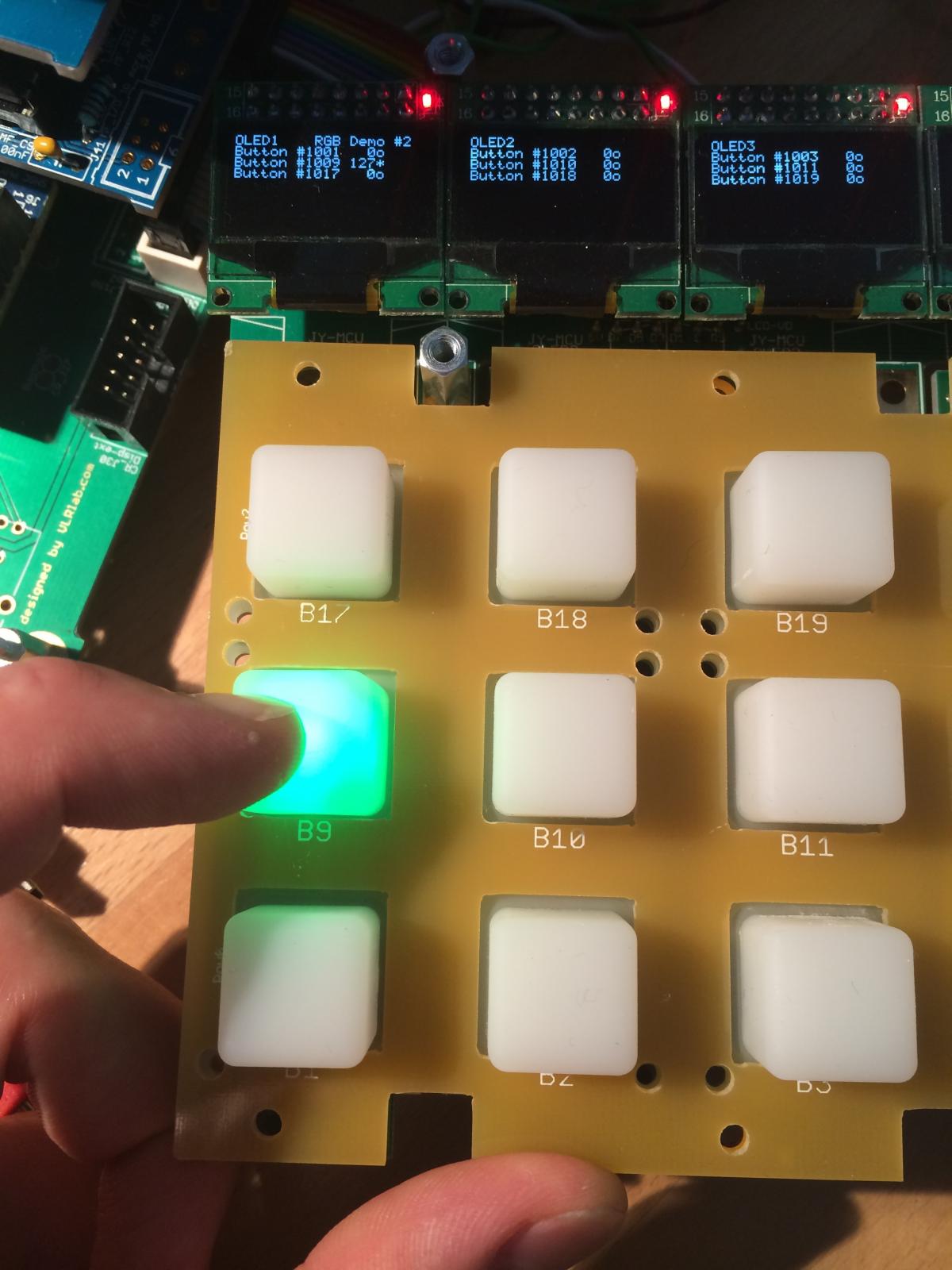
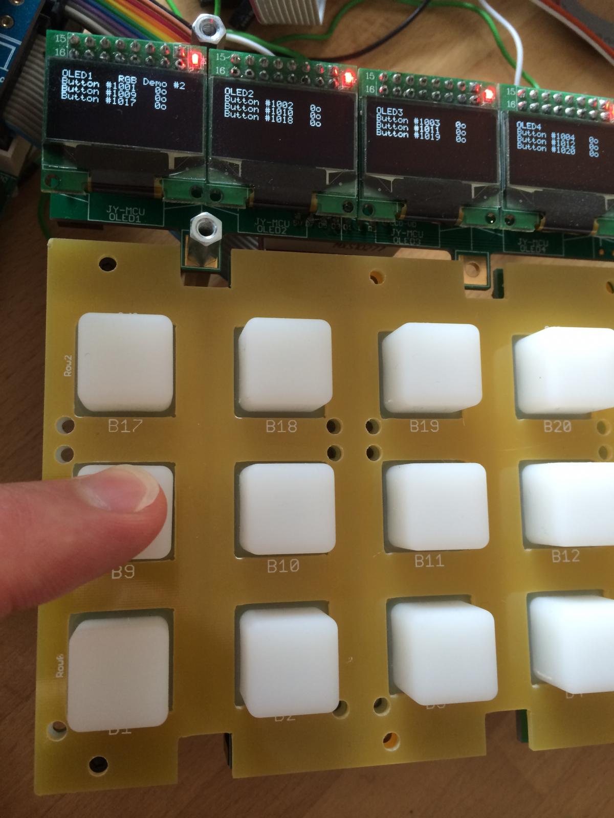
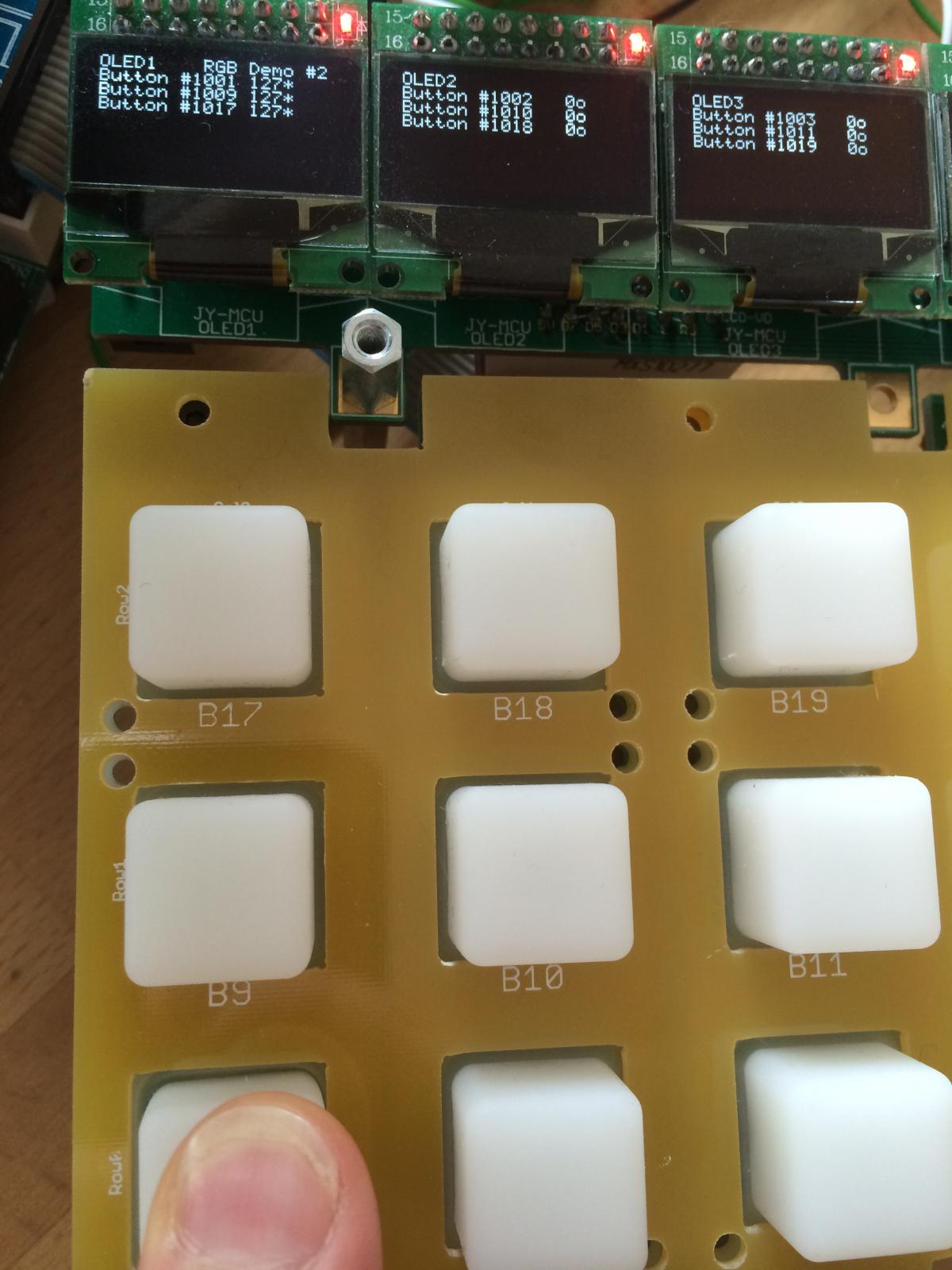
Why does this work RESET_HW LCD "%C" LCD "@(1:1:1)OLED1" LCD "@(2:1:1)OLED2" LCD "@(3:1:1)OLED3" LCD "@(4:1:1)OLED4" LCD "@(5:1:1)OLED5" LCD "@(6:1:1)OLED6" LCD "@(7:1:1)OLED7" LCD "@(8:1:1)OLED8" # In this demo we configure individual brightness levels for the LEDs from EVENT_BUTTON events LCD "@(1:10:1)RGB Demo #2" DIN_MATRIX n=1 rows=4 sr_dout_sel1=1 sr_din1=1 button_emu_id_offset=1001 DOUT_MATRIX n=1 rows=4 sr_dout_r1=2 sr_dout_g1=3 sr_dout_b1=4 led_emu_id_offset=1025 # These button functions forward their value also to LEDs # it's possible to set the rgb levels in the button event, it will be forwarded as well! EVENT_BUTTON id=1001 fwd_id=LED:1025 type=NoteOn key=36 chn=1 rgb=15:0:0 lcd_pos=1:1:2 label="^std_btn" EVENT_BUTTON id=1002 fwd_id=LED:1026 type=NoteOn key=37 chn=1 rgb=15:0:0 lcd_pos=2:1:2 label="^std_btn" EVENT_BUTTON id=1003 fwd_id=LED:1027 type=NoteOn key=38 chn=1 rgb=15:0:0 lcd_pos=3:1:2 label="^std_btn" EVENT_BUTTON id=1004 fwd_id=LED:1028 type=NoteOn key=39 chn=1 rgb=15:0:0 lcd_pos=4:1:2 label="^std_btn" EVENT_BUTTON id=1005 fwd_id=LED:1029 type=NoteOn key=40 chn=1 rgb=15:0:0 lcd_pos=5:1:2 label="^std_btn" EVENT_BUTTON id=1006 fwd_id=LED:1030 type=NoteOn key=41 chn=1 rgb=15:0:0 lcd_pos=6:1:2 label="^std_btn" EVENT_BUTTON id=1007 fwd_id=LED:1031 type=NoteOn key=42 chn=1 rgb=15:0:0 lcd_pos=7:1:2 label="^std_btn" EVENT_BUTTON id=1008 fwd_id=LED:1032 type=NoteOn key=43 chn=1 rgb=15:0:0 lcd_pos=8:1:2 label="^std_btn" EVENT_BUTTON id=1009 fwd_id=LED:1033 type=NoteOn key=52 chn=1 rgb=0:15:0 lcd_pos=1:1:3 label="^std_btn" EVENT_BUTTON id=1010 fwd_id=LED:1034 type=NoteOn key=53 chn=1 rgb=0:15:0 lcd_pos=2:1:3 label="^std_btn" EVENT_BUTTON id=1011 fwd_id=LED:1035 type=NoteOn key=54 chn=1 rgb=0:15:0 lcd_pos=3:1:3 label="^std_btn" EVENT_BUTTON id=1012 fwd_id=LED:1036 type=NoteOn key=55 chn=1 rgb=0:15:0 lcd_pos=4:1:3 label="^std_btn" EVENT_BUTTON id=1013 fwd_id=LED:1037 type=NoteOn key=56 chn=1 rgb=0:15:0 lcd_pos=5:1:3 label="^std_btn" EVENT_BUTTON id=1014 fwd_id=LED:1038 type=NoteOn key=57 chn=1 rgb=0:15:0 lcd_pos=6:1:3 label="^std_btn" EVENT_BUTTON id=1015 fwd_id=LED:1039 type=NoteOn key=58 chn=1 rgb=0:15:0 lcd_pos=7:1:3 label="^std_btn" EVENT_BUTTON id=1016 fwd_id=LED:1040 type=NoteOn key=59 chn=1 rgb=0:15:0 lcd_pos=8:1:3 label="^std_btn" EVENT_BUTTON id=1017 fwd_id=LED:1041 type=NoteOn key=68 chn=1 rgb=0:0:15 lcd_pos=1:1:4 label="^std_btn" EVENT_BUTTON id=1018 fwd_id=LED:1042 type=NoteOn key=69 chn=1 rgb=0:0:15 lcd_pos=2:1:4 label="^std_btn" EVENT_BUTTON id=1019 fwd_id=LED:1043 type=NoteOn key=70 chn=1 rgb=0:0:15 lcd_pos=3:1:4 label="^std_btn" EVENT_BUTTON id=1020 fwd_id=LED:1044 type=NoteOn key=71 chn=1 rgb=0:0:15 lcd_pos=4:1:4 label="^std_btn" EVENT_BUTTON id=1021 fwd_id=LED:1045 type=NoteOn key=72 chn=1 rgb=0:0:15 lcd_pos=5:1:4 label="^std_btn" EVENT_BUTTON id=1022 fwd_id=LED:1046 type=NoteOn key=73 chn=1 rgb=0:0:15 lcd_pos=6:1:4 label="^std_btn" EVENT_BUTTON id=1023 fwd_id=LED:1047 type=NoteOn key=74 chn=1 rgb=0:0:15 lcd_pos=7:1:4 label="^std_btn" EVENT_BUTTON id=1024 fwd_id=LED:1048 type=NoteOn key=75 chn=1 rgb=0:0:15 lcd_pos=8:1:4 label="^std_btn" but as soon as i have this: EVENT_BUTTON id=1024 fwd_id=LED:1048 type=NoteOn key=75 chn=1 rgb=0:0:15 lcd_pos=8:1:4 label="^std_btn" EVENT_LED hw_id=1 At the bottom of my .NGC it sets every Value in the Collum to 127. Now it works. :rofl: Wow. im so glad i found that... It took me an entire day!
-
Hi TK. Thanks for your reply I can't swap anything because of the rubber buttons i made all in surface mount on the Bottomside of the PCB... To me it looks like the column are short but if i measure B1 to B9 its a open line in both sides. also if i push the button B1 while i measure, B1 and B9 are not short connected... I changed both SR 1&2 but it stays the same. If i press B1 the Value of B1,9,17 goes to Value 127 and all three LEDs lit up. as they should but if they get V127 but i don't know from where they get the V127 because im pressing just B1. no clue. i need a beer. :mad:


-
Oh. Maaaaaaaannn... I purchased the wrong disco board!!! :hmm: Does there exist a solution for the STM32F401C-DISCO by now? I don't see it in the bootloader .zip file so i assume not. But wanted to ask first, because i have to order a new one if not... Best regards Novski
-
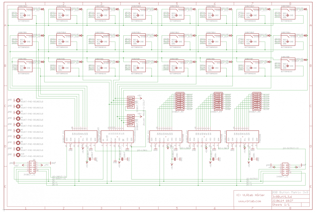
hmm don't now. but i just found that schematic at the end of page 4 in this tread: http://www.ucapps.de/mbhp/mbhp_lcd_ssd1306_alt_port__stm32f4.pdf
-
do you have STM32F4Disco core or a LPC17? The different connection of the 2 parts seam to be correct to me...
-
try this: best regards, novski
-
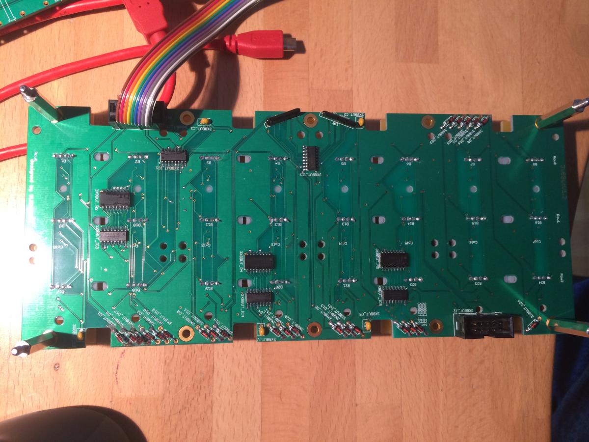
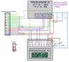
Hi TK. Yes thats correct i use 3 Rows for LEDs and 3 Rows for Buttons from the same Shift Register. I just tryed to change the rows=8 to rows=4 but that didn't change any of the behaviors. I also noticed that the DIN_Matrix line was inverting=1 what i now changed to inverting=0. Is the schematic done right? Thank you best regards, novski
-
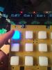
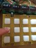
Hi Im Trying to get my Matrix working but have some problems with the commands. Getting back to this in my Vacation im now testing the self-made board of this Schematic: Im trying to program it in MIOS but i can't find out why the second and third button row doesn't react. And instead the First row shows all three Values by pressing the corresponding button of the first row. The LEDs don't light up at all... Based on the Testfiles i added some helpful code to display the pressed Value but in main its from repository: RESET_HW LCD "%C" LCD "@(1:1:1)OLED1" LCD "@(2:1:1)OLED2" LCD "@(3:1:1)OLED3" LCD "@(4:1:1)OLED4" LCD "@(5:1:1)OLED5" LCD "@(6:1:1)OLED6" LCD "@(7:1:1)OLED7" LCD "@(8:1:1)OLED8" # In this demo we configure individual brightness levels for the LEDs from EVENT_BUTTON events LCD "@(1:10:1)RGB Demo #2" DIN_MATRIX n=1 rows=8 inverted=1 sr_dout_sel1=1 sr_din1=1 button_emu_id_offset=1001 DOUT_MATRIX n=1 rows=8 inverted=0 sr_dout_sel1=1 sr_dout_r1=2 sr_dout_g1=3 sr_dout_b1=5 led_emu_id_offset=1001 # These button functions forward their value also to LEDs # it's possible to set the rgb levels in the button event, it will be forwarded as well! EVENT_BUTTON id=1001 fwd_id=LED:1001 type=NoteOn key=36 chn=1 rgb=15:0:0 lcd_pos=1:1:2 label="^std_btn" EVENT_BUTTON id=1002 fwd_id=LED:1002 type=NoteOn key=37 chn=1 rgb=15:0:0 lcd_pos=2:1:2 label="^std_btn" EVENT_BUTTON id=1003 fwd_id=LED:1003 type=NoteOn key=38 chn=1 rgb=15:0:0 lcd_pos=3:1:2 label="^std_btn" EVENT_BUTTON id=1004 fwd_id=LED:1004 type=NoteOn key=39 chn=1 rgb=15:0:0 lcd_pos=4:1:2 label="^std_btn" EVENT_BUTTON id=1005 fwd_id=LED:1005 type=NoteOn key=40 chn=1 rgb=15:0:0 lcd_pos=5:1:2 label="^std_btn" EVENT_BUTTON id=1006 fwd_id=LED:1006 type=NoteOn key=41 chn=1 rgb=15:0:0 lcd_pos=6:1:2 label="^std_btn" EVENT_BUTTON id=1007 fwd_id=LED:1007 type=NoteOn key=42 chn=1 rgb=15:0:0 lcd_pos=7:1:2 label="^std_btn" EVENT_BUTTON id=1008 fwd_id=LED:1008 type=NoteOn key=43 chn=1 rgb=15:0:0 lcd_pos=8:1:2 label="^std_btn" EVENT_BUTTON id=1009 fwd_id=LED:1009 type=NoteOn key=52 chn=1 rgb=15:15:0 lcd_pos=1:1:3 label="^std_btn" EVENT_BUTTON id=1010 fwd_id=LED:1010 type=NoteOn key=53 chn=1 rgb=15:15:0 lcd_pos=2:1:3 label="^std_btn" EVENT_BUTTON id=1011 fwd_id=LED:1011 type=NoteOn key=54 chn=1 rgb=15:15:0 lcd_pos=3:1:3 label="^std_btn" EVENT_BUTTON id=1012 fwd_id=LED:1012 type=NoteOn key=55 chn=1 rgb=15:15:0 lcd_pos=4:1:3 label="^std_btn" EVENT_BUTTON id=1013 fwd_id=LED:1013 type=NoteOn key=56 chn=1 rgb=15:15:0 lcd_pos=5:1:3 label="^std_btn" EVENT_BUTTON id=1014 fwd_id=LED:1014 type=NoteOn key=57 chn=1 rgb=15:15:0 lcd_pos=6:1:3 label="^std_btn" EVENT_BUTTON id=1015 fwd_id=LED:1015 type=NoteOn key=58 chn=1 rgb=15:15:0 lcd_pos=7:1:3 label="^std_btn" EVENT_BUTTON id=1016 fwd_id=LED:1016 type=NoteOn key=59 chn=1 rgb=15:15:0 lcd_pos=8:1:3 label="^std_btn" EVENT_BUTTON id=1017 fwd_id=LED:1017 type=NoteOn key=68 chn=1 rgb=15:4:0 lcd_pos=1:1:4 label="^std_btn" EVENT_BUTTON id=1018 fwd_id=LED:1018 type=NoteOn key=69 chn=1 rgb=15:4:0 lcd_pos=2:1:4 label="^std_btn" EVENT_BUTTON id=1019 fwd_id=LED:1019 type=NoteOn key=70 chn=1 rgb=15:4:0 lcd_pos=3:1:4 label="^std_btn" EVENT_BUTTON id=1020 fwd_id=LED:1020 type=NoteOn key=71 chn=1 rgb=15:4:0 lcd_pos=4:1:4 label="^std_btn" EVENT_BUTTON id=1021 fwd_id=LED:1021 type=NoteOn key=72 chn=1 rgb=15:4:0 lcd_pos=5:1:4 label="^std_btn" EVENT_BUTTON id=1022 fwd_id=LED:1022 type=NoteOn key=73 chn=1 rgb=15:4:0 lcd_pos=6:1:4 label="^std_btn" EVENT_BUTTON id=1023 fwd_id=LED:1023 type=NoteOn key=74 chn=1 rgb=15:4:0 lcd_pos=7:1:4 label="^std_btn" EVENT_BUTTON id=1024 fwd_id=LED:1024 type=NoteOn key=75 chn=1 rgb=15:4:0 lcd_pos=8:1:4 label="^std_btn" While the Midimoitor shows this while pressing and depressing button 1 row 0: [13821.564] 90 24 7f Chn# 1 Note On C-1 Vel:127 [13821.567] 90 44 7f Chn# 1 Note On G#3 Vel:127 [13821.578] 90 34 7f Chn# 1 Note On E-2 Vel:127 [13821.760] 90 24 00 Chn# 1 Note Off C-1 (optimized) [13821.763] 90 44 00 Chn# 1 Note Off G#3 (optimized) [13821.774] 90 34 00 Chn# 1 Note Off E-2 (optimized) Can somebody help me with that? Novski

-
Hi I can't upload a .NGC File to the Wiki because of some restrictions. Is it possible to make that available? best regards novski
-
Hi Marxon Well the first question is a bit complicated because the board is made to use for both cases: 1. Display 1-8, connected to J15A where the 595 is on the Core board 2. where the Select lines come from a additional SPI on J28 (LPC17Core) mixed with J15B over to max. 3 more 595 shift registers. Those drive a extended Display Range of oled 9-32. In your case the second use case is not needed because you want just 4 oleds. If its possible to change the Bootloader so your able to mix the Display types i don't know. Ask TK for that. To make that work you wold definitely need 4 more Select lines. Maybe its possible to take those from the additional DOUTs the new STM32F4 Core has onboard ... Maybe TK Comes around this post some day. He will now better whats possible... best regards, novski
-
I think TK sayed once that one is enough for 32 displays. But i cant find it at the moment on my cellphone. By the way: Im documenting my pcb at the moment. http://www.midibox.org/dokuwiki/doku.php?id=fadercore_-_vlr-8odisp br, novski
-
Thank you Ilmenator! I already forgotten it... :pinch:
-
Hi I made some new pages in past so i thought i was just missing it but now i read all over the syntax and further but i can't find a way to add a new page to the wiki. Do i really overlook it? Where is it? Thanks a lot. novski
-
Hi Zam I didn't forget you yet but i just made my front and will be able to test in a more handy way soon. Its quite hard to test without a solid "fixed" solution. It will take about 3 Weeks so im back to this task in August. best regards novski
-
made new post because nobody reacted.
-
Hi Zam I still didn't had enough time to check that. What im wondering is how it is placed because i dont think its a good idea to connect the minus of a pol-cap to the output of the motor. The voltage has to switch polarity to be abe to drive the fader back and forward. What capacity and volatge did you use for your tests? br, novski
-
Wonderful! 😀
-
Where did you insert that Cap? Between +/- of the motor connections? I have to try this on my deaigns too! 😀
-
Did you alredy tried to connect the shell of all Faders together to GND?
-
I was able to solve that shivering with grounding the shell of my fader and the Frontpanel properly.
-
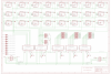
Hi Benoit Thats not all... I make a list of "STM32F4Disco Pins" and "Disp-Ext. 10pin Header" pins: Disp-Ext. Pin 1 : GND Disp-Ext. Pin 2 : GND Disp-Ext. Pin 3 : LCD_Voltage_Option its called J15 on the Core Schematic Disp-Ext. Pin 4 : LCD_Voltage_Option its called J15 on the Core Schematic Disp-Ext. Pin 5 : PA8 Core pin Disp-Ext. Pin 6 : PC13 Core pin Disp-Ext. Pin 7 : PC9 Core pin Disp-Ext. Pin 8 : PC14 Core pin Disp-Ext. Pin 9 : PC11 Core pin Disp-Ext. Pin10:PC15 Core pin Is that more clear? Best regards novski
-
my prefered choice is makepcb.com. Its not fast at all but its the cheapest i found. The Manufacturing days they present are to doubble. :rofl: The last PCB had 3 Months. Normal is about 1 1/2 Months. The Urgent service takes about 1 Month to arrive in Switzerland. But hey check the price... its ridiculous... for fast and smal designs i thake oshpark.
-
Hi Benoit<br /> I am doing the same at the moment but with a different approach. As Thorsten implemented a way to connect many OLEDs in a Serial chain i designed a way to make that connection easy available over a 10pin DIL Header. So maybe it wold be possible for you to implement that at your PCB so i don't have to do same again...?<br /> I just uploaded my Eagle files to github: <a href='https://github.com/novski/Midibox.git'>https://github.com/novski/Midibox.git</a><br /> There is a PDF with two marks that show the connection. I will attach it here.<br /> MBHP_CORE_STM32F4v1.1.2.pdf<br /> <br /> I had no time yet to Layout it. But if you can use my outlines (Dimensions) it wold fit with all my other Layouts to be stacked easy...<br /> It took me quite a while to find a matching form for all Midibox Parts... :-)<br /> its stored here: <a href='https://github.com/novski/Midibox/tree/master/VLR-Eagle%20Library'>https://github.com/novski/Midibox/tree/master/VLR-Eagle%20Library</a><br /> <br /> What do you think?<br /> <br /> br, novski Edit: maybe i have to mention what it is for... 😀 I have made a wiki page. Its still in progress but can help understand what it is for... http://www.midibox.org/dokuwiki/doku.php?id=fadercore_-_fadermodule_for_audio_daw
-
Well if you are building one piece and its not ment to be rebuilt, then i wold recomend to build it on veroboard. Thats stable enough and you will get faster to a working solution... The 8Enc board took me 3 Prototypes to make it work compleetly... ðŸ˜
-
TPIC6C595 works. I have it on my Rotary board for the RGB LEDs of Encoders... Maybe you want to look in to my eagle files. I will upload them right now so the Documentation is not jet made. https://github.com/novski/Midibox You may need the DIP Package. PM me for that as soon as its needed... br, novski