

MaG2k
-
Posts
111 -
Joined
-
Last visited
-
Days Won
1
Content Type
Profiles
Forums
Blogs
Gallery
Posts posted by MaG2k
-
-
hi kristal=
is your bulk order question about an SEQ V4 Case like that T.K. used (17" Desktop Case by Heidenreich)?
If so i am interessted in!
Regards
-
i added 4 PCBs yesterday
-
Great Tool nILS!
Thanx
-
Danke für eure Antworten und Erfahrungsberichte!
Dann halte ich mir Mouser mal als Option offen!
Ich hatte vor wenn bezahlen dann per Kreditkarte!
Danke nochmal!
Gruß
MaG2k
-
Hallo an alle Midibox'er
ich habe ein nur recht kurze Frage...
hat von euch schon mal jemand aus Deutschland bei Mouser Bauelemente und Kleinteile bestellt?
Klappt das? Gibt es was das zu beachten ist? (Zoll, Steuern...oder vertreiben die direkt aus Deutschland?)
Ich frage weil ich schon so meine kleinen Probleme bisher habe. Ich habe schon zwei mal versucht mir den Mouserkatalog als gedruckte Version (kann man sich kostenlos anfordern) zuschicken zu lassen. Bisher kam noch keiner an und das ist mittlerweile gute 6-8 Wochen her.
Wenn jemand von euch Erfahrungen mit dem Bestellen bei Mouser hat würde ich mich freuen wenn sie/er sie hier postet.
Danke!!
Gruß
MaG2k
-
okay i will wait...printed the PCB right now but good that i looked once again here on your thread...
i have a question to you...is there any possibility to add the BLM-connector directly to the PCB? I red Hawkeye told something about a Y-cabel-adapter to make the BLM-connector from both additional Midi-Ports of your PCB. is there only the possibility eighter the MIDI-Ports or the BLM-connector is there a possibility to have both (two additional MIDI-Sets (MIDI IN/OUT3 and MIDI IN/OUT4) plus BLM-connector?
i hope you understand my question.
Regards
MaG2k
-
short question....what are the values of R3-R10 and R11-R17 + R1???
they are not in the circut!
Greetingz
-
oh sorry...i saw right now that direct posting of pics isn't possible.
i have to look how i can upload and link them to here
okay i got it.
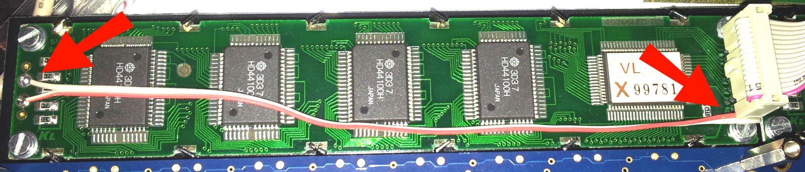
okay as i discribed at last...you can see on the following picture how i connected the LCDs-backlight (anode and cathode) directly to PIN1 and PIN2 of the LCDs Pin-Header.
on the second picture you can see the first type of LCD i have in whole.
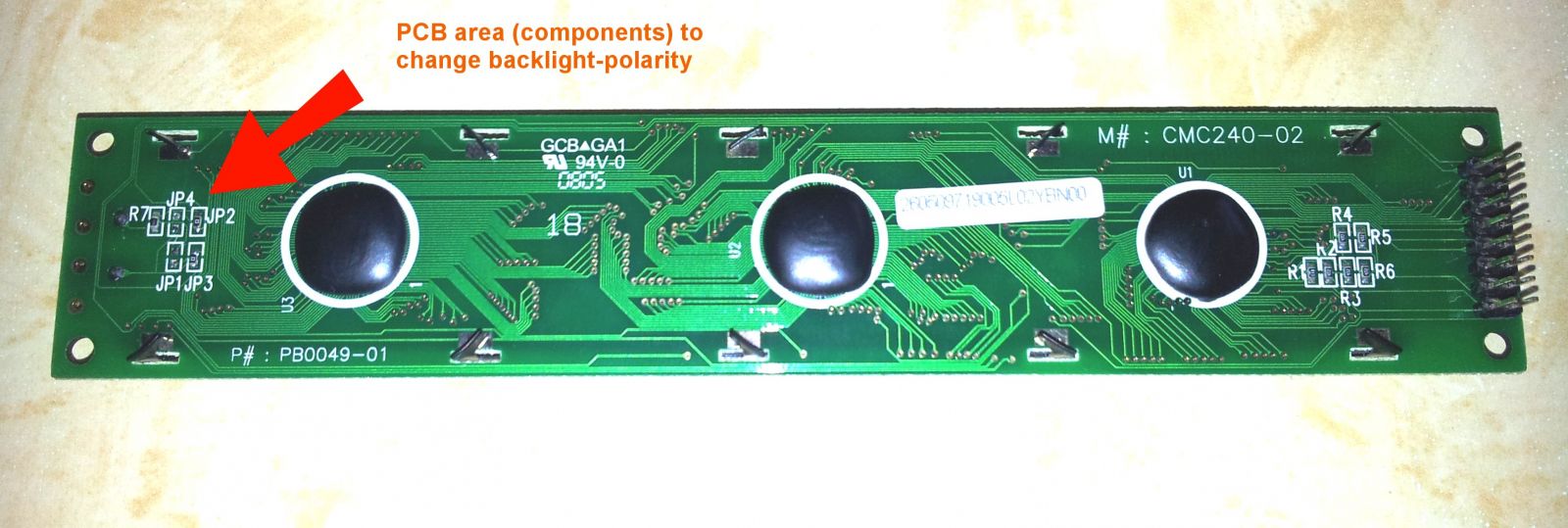
and on the third picture you can see the PCBs area in detail where it is possible to change the backlights polarity on PIN15 and PIN16. (changed JP1 and JP4 to JP2 and JP3)
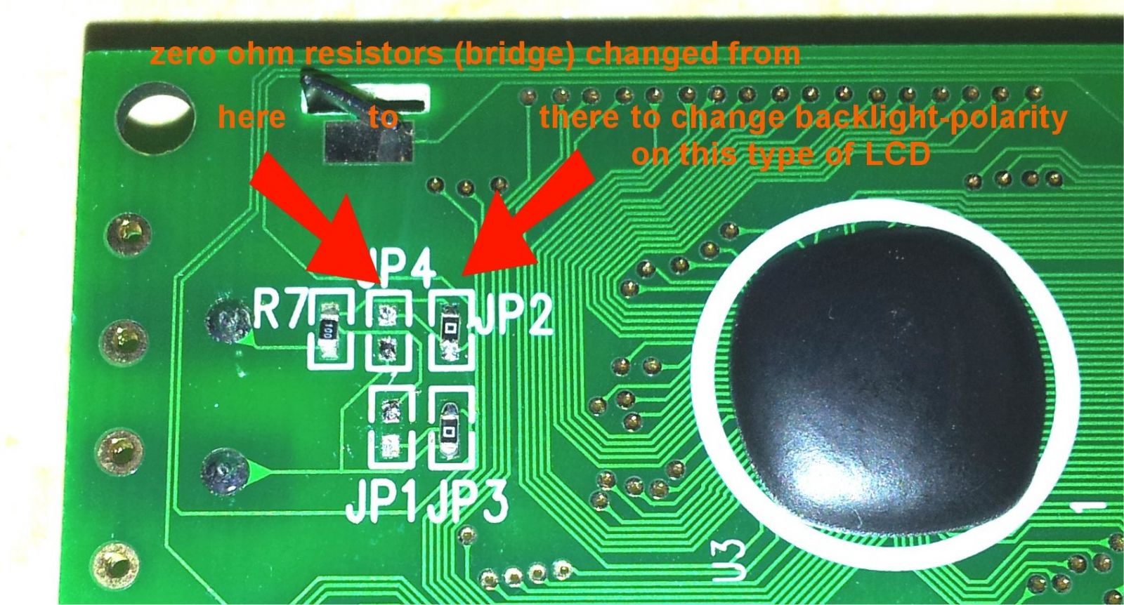
sometimes you have to take a look into the LCDs manual but dont trust them in every detail, cause my datasheet said PIN15 (B+) and PIN16 (B-) but on the panel it was inverted.
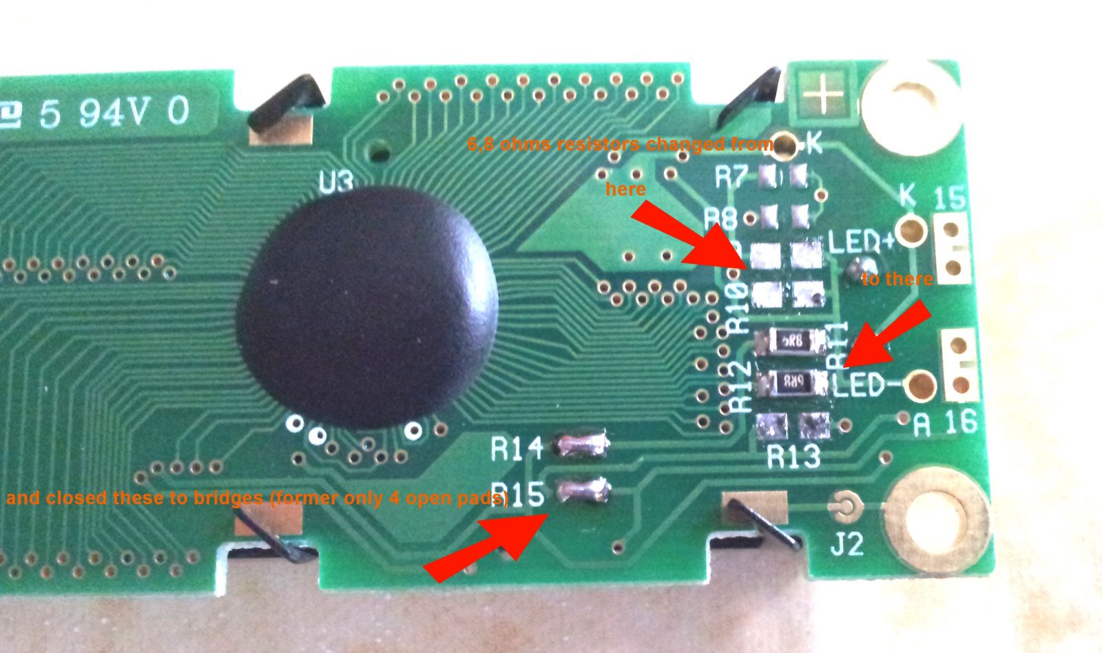
on the fourth picture you can see the backside of the second type of LCD i have in whole.

and on the fifth picture the same LCD in detail. (changed R9 and R10 to R11 and R12 and closed the brindges R14 and R15)
i hope that you can see and understand a little bit better what i tried to discribe. you have to search and measure (short-measuer-mode/beeper) from were to were the wires on the PCB going from anode and cathode of the backlight to PIN15 and PIN16.
Greetings
MaG2k
-
Hi Lamouette,
ist a long time ago i watched you thread...but now i saw...you didn't found bridges on your LCDs-Backside.
You made a photo of your LCDs Backside but only that half were the 16 Pin-connector is. Can you photograph the other half to? Because at "orange-hand's" photos you can see some resistors and some pads of not placed components. on that side it can be that there is that what we are searching.
But by the way...you asked if you coudn't connect the 5V and GND directly to the A and K of the Backlight. Hmmm...as the others told it can work but it can also be that you see yor backlight for a short moment and that was the last time the was lite. But i must say that i did it right that way...cause a use 2 2x40LCDs with only 14 PIN connectors. There the A and K is not connected so you have to make own wires. And that wires run directly to PIN 1 and 2 of the 16 PIN connector from the Corebord. The Bcklight is making light...it works but i have to say the the displays get a little hot for my opinon so it is only for testing issues in use in that constelation. Later i will connect the A and K PINs to 15 and 16 of the Coreboard cause the you have the possibily to dimm the light by using Pot P1 (or P2)...(one is contrast and one backlightintensity).
I hope that you dont got bad Displays with defectiv backlight. as i red you had testet a lot. what you can do is to use a powersupply were you can control the current limit. go to 3v and max of 100mA of current and try to go up tu 5V if nothig happens chance the polarity and try again...only to check if backlight is working...and if you see light at 5V (should be standard on those displays i think) then you can try the way i have solved it (for testissues).
If i have time today in the evening i try to make pictures of my displays, the changes i did on the backsides of thes Displays and the wiring of the Testdisplays i use at the moment so that i can post them here.
I think it will get a little bit clearer when you see on pictures what i did.
so till then...see you
MaG2k
-
Hey Lamouette...
could be that i have some informations or ideas to handle your LCD-Backlightproblem.
I will give you some new impulses...i also building the SEQ V4 at the moment and finished building the LPC17 Core yesterday! I Uploaded the Bootloader as discribed in the manual. Everythings seems to be fine.
Today i startet to build the wiring for the LCDs. I bought two different types of 40x2 modules. I had also the problem to get a manual to the LCDs but because i had two problems. First one LCD-Type 1 had no backlight and problem two, second LCD-Type had full backlight but not controlable via trimmer on LPC17 Core-Board. Let me start with the second problem...full power backlight...reason for it was that the display had 16 PINS but only 14 were wired und the displays-PCB. But no problem look at the Backside of the Display PSB and measure were the backlights Anode and Kathode are connected to the 16 PIN-Display-Header. (at my display A and K was hooked up to PIN1 Vss and PIN2 Vdd of the Display-PinHeader). But i measured were the PINs 15 and 16 are connected to because there was a wiring on them and i found out that there ar open pads on the Backside of the LCD-PCB and some Pads that are wired with zero Ohm resistors (briges). by measuring i found out that you have to close some of these Pad-Bridges and to open others and then the backlightpower doesn't come from PIN1 and PIN2 anymore but then from PIN15 and PIN16 of the Display-Header.
The other displaytype was a little differnt from that because the Backlight on the Displays PCB is wired to PIN16 and PIN15 of the Displayheader...but i had no backlight...cables were correctly made and measured. the Displays Manual said 16 is minus (kathode) and 15 is plus (anode) but after measuring i found out that the wiring is mixed up...so in reality on the Display PCB 16 was plus (anode) and 15 minus (kathode) but also on that display i found a circutry to switch that. there only to zero Ohm resistors had to be change places to two emty Pads. and the result was...now after correcting the displays backlight circutry it works!
Long tex but short help for you...look at the Backside of your Display...search around the backlights connection to the display-PCB for empty Pads...measure the connections from the empty pads to PIN15 and PIN16 of the LCD-PIN-Header (via short-checker) and i think you also will find those empty pads you have to stuff and/or open and your backlightproblem will be solved! :-)
To Contrasttrimmer i have to say that my second LCD-Type needs nearly the complete 5V contrast voltage to make something visible on the screen. the first one is a little more sensitv.
Regards
MaG2k
-
Hi Folks,
ich bin beim stöbern in der E-Bucht auf 2x40 LCDs gestoßen die interessant für den Bau des FM Syths und des SEQ V4 sein könnten.
Da ich selbst erst am Anfang der Planungen für den Bau dieser beiden Geräte bin konnte ich die Displays leider noch nicht auf Tauglichkeit testen.
Laut Datenblatt ist zumindest das CTC-Display HD44780 kompatibel...ich gehe aber davon aus das auch das EVERBOUQUET INTERNATIONAL Display HD44780 kompatibel sein wird.
Hier sind die Ebay-Item Numbers:310405195100 (CTC-Display für 8,46€) und 221040068351 (EVERBOUQUET INTERNATIONAL für 9,40€) aber beeilen...der Sofortkauf endet in 4 Tagen ab heute (27.06.2012)!
Ich halte die Preise für die Displays relativ günstig...die Elektronicriesen verticken sowas ja leider für unakzeptable Wucherpreise und auch Pollin hat langsam gelernt das Displays einen Absatzmarkt haben und verkaufen Displays heute deutlich teurer als das noch vor einigen Jahren war.
Wenn jemand bereits Erfahrungen mit diesen Displays hat wär es schön wenn sie oder er mal hier postet wie es mit der Trägheit der Beleuchtung und den Blickwinkeln so aussieht. Bei mir wird es noch etwas dauern bis ich alle Teile zusammen habe um das testen zu können!
Gruß
MaG2k
gm5x5x5 Bulk Order #4
in Bulk Orders
Posted
Paid!