
lis0r
-
Posts
74 -
Joined
-
Last visited
-
Days Won
1
Content Type
Profiles
Forums
Blogs
Gallery
Everything posted by lis0r
-
My experiments with 3D printing, mostly abandonned.
-
-
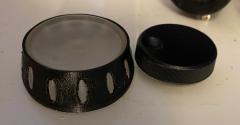
From the album: 3D printing experiments
A parameterised D-shaft knob design I made. It scales well, and works for both the more usual size, and this larger jog dial size. Sadly, the bureau I used provided a very stringy rubber component. -
Hi, I vertical line of pixels seems to have died on the top two rows of my MB-6582 display. I'm guessing this is down to the LCD panel going bad? Thanks! Lisa
-
Given this whole damn thread came about precisely because the files you feed a board house aren't available, this seems pretty damn petty! We're on the cusp of getting these boards built so they can be tested, and the files released as open source. Do you really want to sabotage that by pissing people off to the point where they can no longer be bothered? Because that's all you're going to achieve by reairing old vendettas!
-
Sorry for disappearing again - work is absolutely mental. I've been given permission to do a single small batch of the boards, which with my board house is 10 boards. If TK gives his permission, I'd be more than happy to open source the files. If someone else is willing to take over the boards under the same conditions, equally I'd be happy to pass them on, but again, permission from TK would likely be wise.
-
Hi all, Sorry to disappear for a while. Everything has been going wrong for me! First I lose my front panels, and then work becomes a nightmare - the company I work for is being sold, and everything is looking very hazy from this point out. I'm pretty sure the PCB files are good - I went over them in software and all the nets look good, they look right when I upload them to DirtyPCBs, and Gerald graciously tested the fit as best the image would allow. However, I can't guarantee the boards are going to work until I've had a chance to build one up, which is where we come to the problem. I don't have any of the components, and I don't have a core32 board. With the future of my job looking shaky, I can't really afford to buy all the parts and the risk of ordering the boards. I could sell the boards I don't need untested with no guarantee, but that's not ideal, and I'm not overly happy with the idea. If there's a willing, trusted member of the midibox community who's willing to abide by the restrictions set out by T.K., it could possibly be better for me to pass my project files on to someone who's more able to see this through to completion? Sorry I've been unable to help as much as I'd hoped - I very much understand everyone's frustration. Lisa
-
Hi all, I'm afraid I've not ordered PCBs yet. Unfortunately, I've managed to misplace my control surface aluminium panel, so I can't check if the holes will line up. The most recent PDF file I printed above seems to be the right size - I printed it out and stitched it together, and the dimensions looked correct. If anyone else with a panel can do the same, and check the holes do line up, then I'll be a bit happier that the PCB is right. Lisa
-
Sadly my home printer is not really good enough for the task. Hopefully I will find the time to try printing out the layout elsewhere so I can compare it to panels, etc. early next week. Anything anyone can do to help regarding layout review would be much appreciated.
-
Those are exactly what I used for reference :) The thing is, I have gerbers, so once I'm happy with them, I can get boards made.
-
http://www.bismuth83.co.uk/~lisa/v4.pdf When I load this in preview, the dimensions look about right, so fingers crossed this has converted properly this time.
-
Ignore this, it looks like the conversion from EPS to PDF has screwed it up.
-
I believe L31 is rotated on the original CS PCB, so I duplicated that to ensure the same instructions could be followed. i will have a think about the trace - the board is autorouted, and the tool is a bit of a pain to use. i'll try and find the time to make a PDF, hopefully that will deal with scale better than SVG.
-
Yeah, I've used the rule checks in Eagle before, but this board is too big for the free version! It's passed all the tests (automatic and manual) that I have available to me, but due to the nature of the board, it'll cost a non-trivial amount of money to run, so I'm trying to avoid getting it wrong!
-
An SVG of my layout is available from http://www.bismuth83.co.uk/~lisa/v4.svg If this needs converting to PDF to be printable, please let me know. Because I'm allergic to the bad GUI that is kicad, I built this design using PCB-RND. If anyone has sufficient knowledge to review it electrically, I can send them the source file that will be used to generate gerbers, etc. To protect the midibox IP, I won't be making it publicly available. Thanks! Lisa
-
Thanks Gerald - I will try and sort something out for you to look at this evening. Thanks!
-
Hi all, First things first: I've got TK's and Wilba's blessing for this. I have almost all the parts required to build a SEQ v4 except the control surface PCB, which has been out of stock. So I've recreated my own clone from the available schematics and dimensional drawings. I have permission to run a small batch, and sell those surplus to my personal requirements. Would anybody else be interested in this? Is there anyone with the needed skills who'd be willing to help me verify the board layout before it gets sent for manufacturing, please? I'm pretty sure it's right, but I'd like to make sure it's right first time. Thanks! Lisa
-
Hi Phatline, I'd suggest reading up on some sampling theory, specifically regarding the Nyquist frequency. Once the signal has been low pass filtered, it won't be discernible from a fully analogue signal. Low pass filters include a filter circuit, which for audio could be as simple as an RC filter, but also persistence of vision also acts as one, which is why you can see films, TVs, etc. Most microcontrollers have dedicated hardware to help with PWM generation, but I'm not sure of the specifics on STM32. Normally it involves selecting a switching frequency, and then setting a duty cycle - what proportion you want it on/off. Very easy to program. You don't select your capacitors based on your desired output frequency, but based on your sampling rate - then you just play back a sample. Lisa
-
Wouldn't it be easier to drive the LEDs, body shaker, etc. from PWM modulated outputs, instead? Given you'll want power transistors between the controller and the effector, that would be more power efficient too. The PWM can drive the transistors rail to rail, leading to better power efficiency and less heat generation. If needed (and there's a strong likelihood it wouldn't be) you could use a reconstruction filter between the power transistor and the effector to get a truly analogue signal. Also beware back EMF from the body shaker! You probably wouldn't want to connect it directly to a DAC or a PWM output. An H-bridge driver would give better protection to the circuitry. That leaves audio, but the STM32F4 discovery board already has an audio output on it, so you could use that or copy the circuitry? I've considered similar things myself, using an H-bridge to drive bipolar TENS signals through an isolation transformer in addition to lights, sound, etc.
-
Me too - no one seems to have them on the fleamarket :(
-
Hi all, I'm looking to buy a SEQ V4 control surface board, preferably unpopulated. Does anyone have a surplus one they're willing to part with? I'm in the UK. Thanks! Lisa
-
Will this new layout fit into the old aluminium cases, or should I still plan on obtaining a current SEQ V4 CS PCB?
-
Oof, this thread is getting difficult to keep track of. Perhaps we need the current proposal in the wiki somewhere? I thought Cherry MXes were still the favoured component. It's looking a lot like this won't be compatible with my case, so I suspect it's not going to be for me anyway. Guess I better keep an eye peeled on the shop for if the current CS boards come back into stock.
-
Sadly, I'm pretty bad at drawings too, so I'll try and describe it better. Sorry about the Poker2 reference - I read that it did not use a separate stabilising plate. 1) At the back, you have a solid, flat, metal back plate. 2) The next layer up is the keyswitch PCB, which is bolted to the solid plate on standoffs, leaving space for the PCB stabilisers and plungers of the keyswitches. The keyswitches would be staked with diodes to the PCB, and so wouldn't need a stabilising plate. 3) The next layer would be the boards for the encoders/aux switches. Instead of being on blind standoffs, these would have holes in the PCB, and sit on spacers. 4) The next layer would be the front panel, which is bolted through spacers, through the encoder boards, through the encoder board spacer mentioned above, and finally through the back plate. At the side without an encoder board, it could be bolted straight to the backplate through a single spacer. This pulls the whole sandwich together. The back plate provides stiffness and reinforces the front panel, and the back plate provides a surface for having lots of mounting points for the keys, without consuming all the internal space in the case. So 1+2 have lots of mounting points, to provide through support, and then 1+3+4 provide rigidity and overall mounting. Because 1 only involves cutting and drilling, it would hopefully be cheaper to manufacture than the cutting, milling and folding that a keyswitch stabiliser plate design would require.
-
Hmm, or maybe dispense with the switch plate entirely, PCB+diode mount the swiches (like a poker 2). Instead, have a single simple plate hung from the left and right of the front panel, and maybe the middle by the encoders, reminiscent of IBM keyboards. The PCBs then mount to that. It'd be heavy as hell, but much stiffer, and easier to have manufactured? I've just realised this design dispenses with the big datawheel! A pity - I'd designed a parametric clone of the ALBS DK16-190V3 in OpenSCAD. I was toying with the idea of printing one at iMaterialise at the appropriate size to test the design.
-
Regarding the inner plates, I was reminded of the C64 keyboard, where tiny screws were used to mount the PCB to the plate, then the plate mounted to the front panel at the edges. Is there any way this could be used to simplify the internals.