

Phatline
-
Posts
1,285 -
Joined
-
Last visited
-
Days Won
72
Content Type
Profiles
Forums
Blogs
Gallery
Posts posted by Phatline
-
-
37 minutes ago, latigid on said:
For your drum modules: always cool to see, but many of these have PCBs available already e.g:
http://www.falafular.org/modules/
http://www.hexinverter.net/pcb-projects/
These are known to work, so might save some time and money.
For a "bit bashing" register-based AOUT, see AOUT_LC on uCapps.de
MB808 runs on Core8.
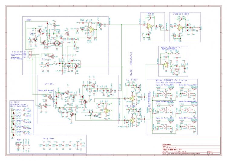
TR606 HH+Cymbal? - with Mods(or place4Mods) - cant see it anywhere out there
AOUT_LC was the right hit - thx - i will do it that way > http://www.ucapps.de/mbhp/mbhp_aout_lc.pdf
I think 8 Bit is enough... and we could use 2x8Bit to make 2 Accents Seperatet, so HH+CY have a own Velocity, and BD SN the other... i think that give more flexibility.
@Psykhaze Orginal HiHats and CY have no Noise (i think...)--- thats a Mod - (to have the ability for more 808 hats)
-
is there any Driver-code out there - in the MidiboxWorld - to use the onboard Audio DAC for CV? (0-127)
i just need it for Velocity Control for the Accent of a TR606 which need a Voltage from ~4V to 15V (a little scale with an OP amp should do the trick hardwareside - i think)
In the past i have done Accent with a Shiftregister, 8 Varistors and a Transistor... worked well, but steppy.
thx phat
-
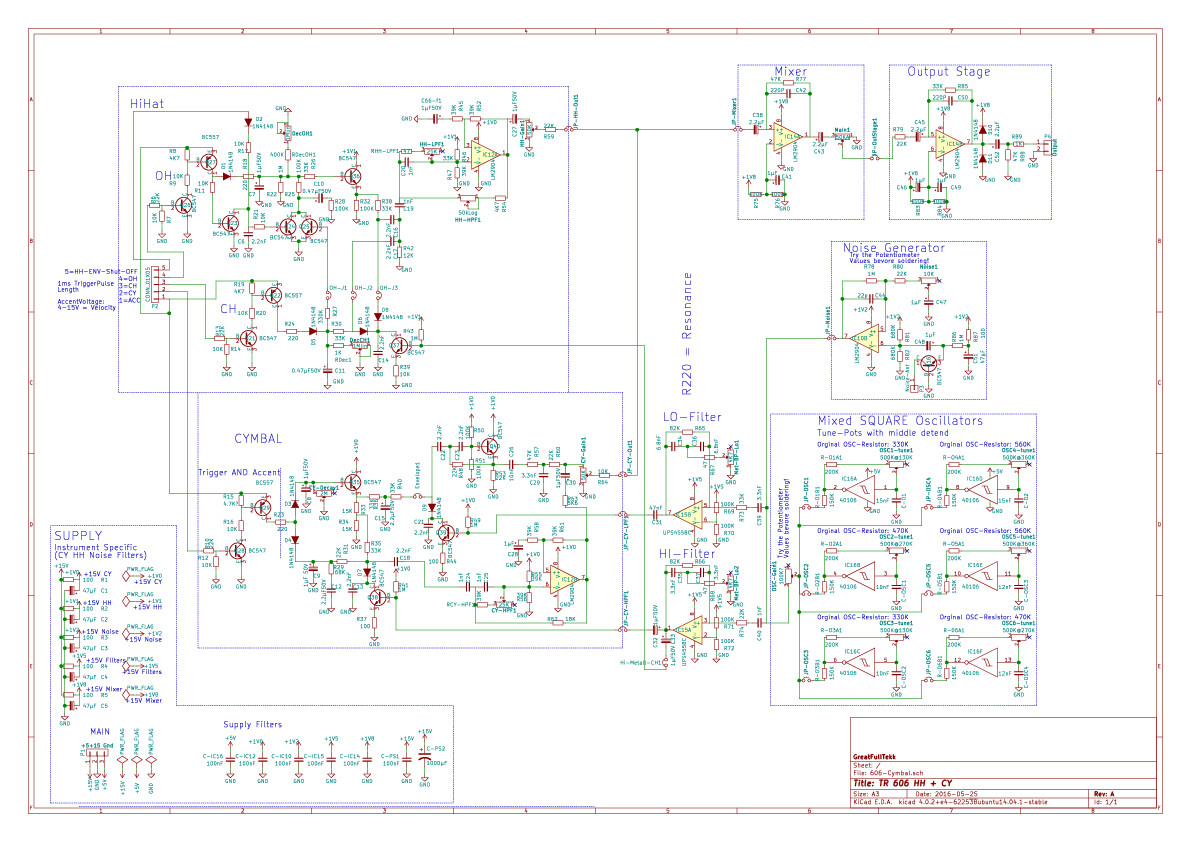
Here my last version with the snare in it... just combine the snare section with the noise section, delete the rest - except some parts of the power part which you will need.
I will use the mixer by my side to get the orginally OutputStage-Filtering, and maybe also as some kind of Overdrive...,
since we are modular, i will add a Pinheader and a Input Jack on Frontpanel for your BD/SN - to get into the mixdown... for me its easy, CY CH OH are good Triad to mix analog...BD SN are very differnt to each other and to my Triad, anyway i will make Input Jack for that - question is 1or2 Jacks.
--- if you have already a Module System, then use the Module Power System Connector, we need +15V and Ground, i will need a extra 5V for the Osciallators and the Core Module (later i will copy that part from you, because i dont have a system supply)
we could use a tiny 8Bit core... 32Bit has a DAC onboard, which we maybe could use for Velocity Control. (also 32Bit Plus is, i have already a program for it, but i have also some 8Bit devices, and the code is?t that difference.(MIOS32...string...)
-
 1
1
-
-
update:
+ noise source which is originally for the Snare Drum - is now mixable to CY and Hats
+ mixer section - so HH + CY-Mixdown should sound like 606... (filters? Impedance)
+part of the original Power Supply Section which give every instrument its very own power source (left downer corner) - i don’t know exactly why they did this...
+the 6Square Wave OSCs for the Metal sound: now are tunable with trim pots - in order to tune it to my Setup (A@~432Hz..) (by the way: 6OSCs? 606 interesting...)
+added some explanation to the schematics - which i got from thru the internet research...
+Add Jumpers for every Output from the different stages - in order to better debug the prototype - and to better mod - and to better tune - and to better make a modular...
+pcb will be bigger then excepted
- i lost the orginally Part Nrs as a mistake... i only restored the OP-Amps and Transistors - (bad)
-
thx
i put there a 2M now.
i dont found backgroundimage settings... but a good idea to look at the orginal pcb.
-
Shematic are all over the net: http://privat.bahnhof.se/wb447909/dinsync/service_manuals/TR-606.pdf
Module: CY + HH on one Modular Module (Gnd, +15V), driven with a MidiBox Core32 - the midibox side is already programmed and tested a lot... there is somewhere a Topic on this....
Why only CY+HH.... whell, i have already a TR606 but i only use the Cymbal - and for that it is to big, so why then HiHats also? because they use the same Metall-Oscillators... but maybe i skip the HHs (they take much place)
the midibox side i made 2015 here:
but sorry shematic are very tiny because of Forum Move and Dead Gallery Pictures....
-
@Zam thx!
i drawed the Cymbal and HiHat Section of the TR606 into Kicad Shematic... the pcb is still left, i dont have the mood right now... but maybe it helps anyone - anyhow...
I have used the orginal NRs (R178...) and the MODs for this Section are in it...
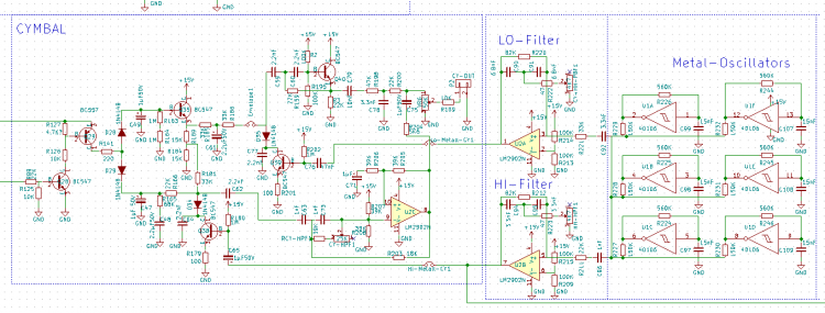
it would help if KiCad whould place the components like or simular like on the shematic... > säcke.
-
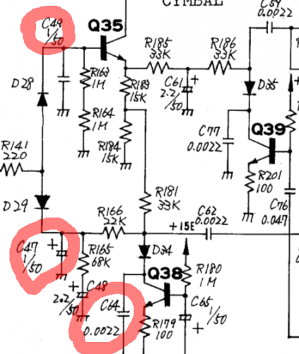
in the picture below - i marked 3 capacitors... i dont understand what that mean:
C49 - 1/50 ---- i think that mean: 1µF 50V ... but 1µF is untypically for a unipolar Cap?
C47 - 1/50 ---- 1µF 50V Electrolyt cap - could be
C64 - 0.0022 .... ceramic 0.0022F? = 2200µF cant be > way to much for a ce
rco...
(by the way its the Cymbal circuit of the 606)
-
...this time only one cam...
-
1
-
-
thx,
we will cam more of our weekly jams.... except the beer parts

-
memory donna summer
-
7 hours ago, Psykhaze said:
First part :
I remembered about electronic drums and piezo sensors for velocity detection. I looked some around the forum but did not find any refs for a piezo that could fit.May someone advice me a mouser ref@Phatline Edit : is This Piezo ok ? (seems u used some piezo for your bongo trigger)short answer: YesNo maybe...but they are allmost the same i have ordered
i am still in beta state...give me a week or two... maybe i know more then... in the mean time i have a lot of "if" "maybe" "i gues"
 it works but not testet on real bongs (only on table...)
i have ordered that: EPZ-27MS44 they are not wired (you have to solder a cable) and have no feedback loop, but they have all-much the same Resistance (400-500Ohm)when soldering a wire you have to reduce the heat of the soldering iron...with 450°C you burn a hole in the top-metal...300-350°C is ok
but they are very big about 4cm diameter...maybe for a PAD-Solution smaller are a better choise: mouser they are 1cm and used as loudspeaker thery are for high-tone (vs midtone), dont know what that means in the sensoric way, but mine have peak when hit hardest about 5V.
your linked piezzo have a feedback-loop - that is sometimes needed when you use it as loudspeaker(the 3rd wire)... but maybe the have use as triggers too? why that?
>>>problem: coupling vibrations from one pad to the other: if you hit the piezzo to hard, vibration goes to the other pad... this is no problem for me, because i use it on bongos...they vibrate also to the other bongos but not that much, so i programmed software side a minimum voltage threshold (software decouple) which also reduce the velocity sensitivy a bit... much more of course when you use it in pads
triggerpads are a other story...and here comes the Feedback loop in the game > maybe wired on a Digital Input, it helps to find out the correct piezzo element > means if you hit piezzo 1, the DIN Pin 1 gets HI, the software now knows - ignore all other Analog Inputs from the other Piezzos for this moment...so you have the full velocity (stroke the pad)... but that is a bit tricky software side, because- what happens if you hit more pads @ once.... like i said a lot of "if"
also the hardware decouple... the stand-the-base-the-case should be very heavy (kilos), it should not vibrate when you hit a pad, because every vibration give Piezzo information on all other pads
then the pad, on its backsidein a hole of diameter about the diameter of the piezzo, in it the piezzo.
and between them case and the Pad should be a very good shock absorbing material, which? > dont know? but they should make a good decouple job...and it should not be to loosy because loosy means vibration - and vibration make fail-triggers on the other pads - a internet search for such triggerpads for drummers should bring more information...but thats not my site...i am on bongos there are other problems.
just my 2 cents
-
The Test Equipment

This Kroko cand hold on surfaices up to 4cm (piezzo - clamp)
572a2859eefc1-

The Piezzos dont need Active components...

The Electrete Mic- Stands ---- the will be placed inside a bongo (since a bongo is open at the ground)

Midibox Stuff...

-
2 hours ago, latigid on said:
design all of the parts from the beginning, so how the front panel works with the case, the connectors, heat management etc.
Something that a 32-bit Core might be useful for is display options. Part of the mystery of FM synthesis is how all of the operators/modulators interact to create your sound. If there were graphical representations of waveforms/levels/routing I think that would be a great contribution.
agree!
-
A new concept:
The Piezzo take the Wood Hits
The Electrete take the Skin Hits
the software decide which one was hit, because of Amplitudes.
some first thougts about how to decode that 2 differnt Mics...

How to Finetune the Amplitudes > Tune the Setup for your Bongos:

1.Select Trigger-Input
2.Press AutoSet
3.Hit The Bongo HARDEST, and be Quiet
3a.On Skin for Electrete Inputs
3b.On Wood für Piezzo Inputs
4. >>> The Trigger goes now into an AIN which is set for to high Resulution > 1K... instead of 0-128, so Auto do what? > I got from ain e.g. Values from 45minAmplitude & 600maxAmplitude.
so 600 is peak Amplitude, and 45 is silence or better: the RoomNoise
now we have to scale that for a Note Velocity Value 0-127... so first
max-min=new max (600-45=555)
min=0 (instead of 45)
555/127=4,37
------ these are Settings----- Saved Variables on SD-Card (a Preset)
All Values coming from the Bongo now get calgulateted with -45 /4,37 to get 0-127 Velocity Values
-----
But I dont trigger them out now... now the "fun" or pain (ahh i like it) begin with, calculate - which one was hit now? Skin or Wood, is the Retrigger time over? Are the Amplitudes still fallin? Retrigger? or do Nothing... and so on
-the pain maybe will be to get exact AIN-Values... the AIN is more programmed for Controller is?t it? > avoid to much data mess and jumps and other (maybe) programmings... i will see
the "Dont-Retrigger" time has to be set by Hand... depending how fast you can play...
-
good idea... if someone make a pcb and or OLED-Bulk i am in
to "verwurst"-code...i would use some modules in first case for aout-Filterbank-version.... and many other cases
-
each display show labeling and values for 2 encoders (one row above, one below)?
-
they drive the LM324 with 8V.... how ever, a mcp6002 is also in the basket
edit: they connect the Piezzos directly to the AINs https://www.sparkfun.com/tutorials/330
-
Just now, latigid on said:
To protect from overvoltage you connect the anode to the pin and the cathode to 3v3. This ensures nothing greater that 3v3 can pass, it's also normal to include one or two current limiting resistors. To protect from undervoltage you connect the anode to ground and the cathode to the pin.
very clever
---the OP-Amp- as Limiter.... do the Shematic below that trick?... since i am not very good in analog basics
i found the EDRUM (DIY) Project which also uses Piezzos, here is the Analog Shematic
which is connected to the 4051ers on a Microcontrollerboard - so it is for 0-5V, when I use the multiplexer Midibox Variante I could use it 1:1 right?
http://www.edrum.info/schematics.html)

-
very interesting link

i will try that piezzo first, I already soldered the prototype AMP today.. piezos and krokos are ordered.
Schottky? did that work similar like Zener?
while Zener 3,3V exist: http://www.reichelt.at/ZD-5W-3-3V/3/index.html?&ACTION=3&LA=446&ARTICLE=145329&artnr=ZD-5W+3%2C3V&SEARCH=zener+3%2C3
i have real troubles to find a 3V Schottky?
-
Idea (good? false?better?)
The lower placed Electret Microphone (eg this: MCE-100 ) is reacting more on the bass sounds, because of its Location where are more low-frequency-signals, and because of its BANDPASS-Filter Settings. The Filter is needed because the AIN will react on Amplitudes... the more specific the Filter is set for a specific sound - the more accurate is this Amplitude methode - to get Velocitys...
The higher placed Electret Microphone is reacting more on the Direct Tap of the Skin or Wood, to avoid FALSE-Triggering from the Middle-Skin-Taps (Bass-Drum) it is place more near the Wood, and a Bandpassfilter that is set for MID-BandPass-Filter-Settings.... or so....
The Zener Diode should clip above 3,3V which is the max. Voltage for the Cores Analog Inputs
ndensator bestimmt die untere Grenzfrequenz, je grösser dieser ist, desto tiefere Frequenzen können übertragen werden.
 Maybe there are better ways? - please tell me - i will draw a new shematic then.
Some Test for that Capsula...: http://www.loetstelle.net/praxis/elektretmikrofon/elektretmikrofon.php
The Output-Voltage goes ...from a few mVpp to over 100mVpp... you need a amplifier with a great dynamic bandwide....
hm to bad out of stock: https://www.adafruit.com/products/1063
-
WORKED for STM32F4 and LPC Cores @ Reichelt.de:
NOT WORKED!!!! I bougt @ conrad 4x that (dont do that!!!!)
Transcend "microSD ADAPTER": I have no MicroSDto Card that work with that adapter, it is difficult to get it working on LINUX, because of the BAD contact from MicroSD to SD internal, LINUX get many connects and less USER-Made disconnects ... thats a problem under linux because - if you dont Remove the SD-Software side, it can happen that no new SD card will shown up... restart and so on...that is a sign that the Contacts have not enough pressure to ensure a good contact.
When you moove a microSD Card in, it feels like "that should fall out from earth-gravity"
and on a STM32F4 it can be seen by my application, but when i start to write or load from that sources it hung up.
DONT USE THAT TRANSCEND ADAPTERS: PREMIUM CLASS WTF?
-
do you have some usefull input about:
how to get a drum trigger from a bongo drum (best would be velocity sensible) - with midibox?
i thougt about microphones... but when it comes to electronic amplified music, it could make fail-triggers...
then i thougt about to mount the microphones in the resonance body of the drum... but there mainly is the bass sound of the signal, while hi tones (outer ring or low velocity playing) are almost not hearable there...
but what to do with the mic-signal...
ok first make it simply take only 0-xV instead of -0+Volts...,
amplifie it to a range from 0-3,3V (stm32F4) a amp with built in Clipping?
connect to the 8 ain inputs onboard
write a program.
or is there any Bongo-Trigger-Crapper out there that could get connected directly to the Skin?
i dont know much of this, but i want to jam with an bongo player
-
mb_ng? > mf_ng?
my expirience:
working: 2x40LCD connected via 30cm grimped cables to stm32f4 ...
pic based - working 20cm long cables...
i think it can be a whole lot more cm then this..
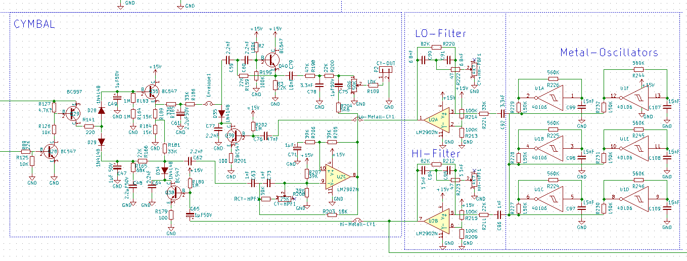

TR606 CY+HH Kicad Shematic (Capacitor labeling on old shematics)
in Miscellaneous
Posted