flyweight303
-
Posts
19 -
Joined
-
Last visited
flyweight303's Achievements
MIDIbox Newbie (1/4)
0
Reputation
-
Wow that looks just awesome. Thanks for sharing. Cheers Tim
-
Hey Psykhaze i did my study and meanwhile got an opportunity to buy the yocto kit so I think its not a bad idea to get some boards from you. I will build this project without a sequencer and will use TK's Midibox seq to drive it.
-
Hey JK, are there any enclosures available? could you hint me on some source? its great to see how TK's brainchild was adopted in the Yocto808, Nava 909 and the TR9090 is this btw the project: http://www.synthage.com/Sequencer/default.html ? cheers Tim
-
Ah now I get it. The documentation helped a lot. Osc is supported over WiFi on lemur android. So if I connect the midibox to a WiFi router it should work. Better even because its wireless. So the whole USB Ethernet is pointless :) thanks a mil. Cheers Tim
-
Hi Shuriken, good tip for an Ethernet module. The reason for USB Ethernet is the ability to connect an android device and run lemur.
-
https://github.com/fetisov/lrndis I did some digging on lemur on android. It supports only direct cable connection via usb-tethering . however there seems to a working rndis driver available for the stm32. Could this work with freertos? Are there any applications other then lemur android which could benefit from a USB ethernet implementation on the seq4?
-
Hi Thorsten, Indeed the sdcard command failed, i just soldered another sdcard socket and it works! I am really happy that i didn't braek anything while troubleshooting. Still don't know what was so different with the socket which didn't work, but still really happy that it works now. Thanks all, Best regards, Tim
-
STM32F407 Discovery not detected in Win 8.1
flyweight303 replied to flyweight303's topic in MIDIbox SEQ
Still no luck with the SDcard, All pins are connected ok. 9 NC 1 PB2 2 PA7 3 GND 4 VDD 3v 5 PA5 6 GND 7 PA6 8 NC SD cards Shield connected to GND When connected to micro usb LD1 is blinking. When ejecting or inserting the SD card nothing hapens. 3 v is available on pin 4 and 2 data lines The correct IC's in the sockets, the resistor network connect with common pin on 1. After flashing the seq4 app should some jumpers be removed?
-
STM32F407 Discovery not detected in Win 8.1
flyweight303 replied to flyweight303's topic in MIDIbox SEQ
MmM i just removed the extra pin. desoldered it and bend it slightly to remove the contact. On 3 places i measure 3v is this OK? I am afraid i toasted the data pins from the stm32f4..... -
STM32F407 Discovery not detected in Win 8.1
flyweight303 replied to flyweight303's topic in MIDIbox SEQ
Thanks CJ55, it looks my holder is correctly installed. I will check if 3.3v is coming in on pin 4. -
STM32F407 Discovery not detected in Win 8.1
flyweight303 replied to flyweight303's topic in MIDIbox SEQ
Mmm OK so if you check the pin out how I have it connected it looks fine. I now start to doubt if the core board is correctly working. I think I need to check if 3.3v is going to the sdcard. -
STM32F407 Discovery not detected in Win 8.1
flyweight303 replied to flyweight303's topic in MIDIbox SEQ
Check the data sheet, I used that holder, it has 1 pin more than the one on the original bom. So pin 3 and 4 are on the holder not pin 3 and 4 on the PCB, or on the actual sdcard -
STM32F407 Discovery not detected in Win 8.1
flyweight303 replied to flyweight303's topic in MIDIbox SEQ
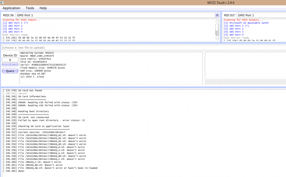
When is send the SDCARD command via MIOS studio then get error: reading CID, CSD -256, SD Card not connected. Is there some way to force the card detection on the socket to be always thrue? I might soldered the socket wrong so the card detection does not work. -
STM32F407 Discovery not detected in Win 8.1
flyweight303 replied to flyweight303's topic in MIDIbox SEQ
So i managed to flash the core with the mios bootloader and sequencer 4 application. I first flashed midibox_seq_v4_088_pre9 but the sd card is not detected (4GB fat32). Messages: SD card not mounted If i take the sd in and out while connected to miosstudio nothing happened. i reverted to midibox_seq_v4_087, and also tried the GM midi driver but MIOSStudio fails to see the SD card. I used the following reader, and soldered pin 3 and 4 together. http://katalog.we-online.de/em/datasheet/693061010911.pdf Pinount from sdcard holder solderjoints to the STM32F4 core board. -8 not connected -7 PA6 -6 GND -5 SCK PA5 -4 VDD -3 GND -2 PC5 -1 P82 -9 GND The sd cards holder case is also connected to ground. Does anyone see a mistake? how should any SDcard be connected to the Coreboard? otherwise i can still try it with wires. How i can further test if the coreboard is soldered ok? The 1k resistor network is soldered with the letters faced to the right of the board.The ic's are connected as displayed on the board. Any help more then welcome, Best regards Tim -
STM32F407 Discovery not detected in Win 8.1
flyweight303 replied to flyweight303's topic in MIDIbox SEQ
Issue was due to the cable, now with a new micro usb cable and the stlink util in compat winxp sp3 mode everything is fine