

Nirokesan
-
Posts
46 -
Joined
-
Last visited
-
Days Won
1
Content Type
Profiles
Forums
Blogs
Gallery
Everything posted by Nirokesan
-
TK, Thanks so much, I'm back in business! Lumi pot dims the screens to black, but contrast doesn't do anything at all no matter the Lumi setting.
-
Great news, TK! Thank you for your efforts! I will fix my connections when I get home and see if things work again. This however does not explain why Evil is still having a problem with new LCDs and correct connections....
-
Yes, I just looked at a few other pics of working LCD connections and see that they are opposite to mine. It's possible that when I connected my LCDs to run bootloader and MIOS, I went by the datasheet.....and when I later assembled my enclosure, I went 1:1. So does that mean these LCDs are cooked? Need to order new? I will attempt to find info on my LCDs, ordered from eBay I will still run "testlcdpin" when I get home (if I can figure out how)
-
TK, Thank you for your reply! I can only answer your first question right now because I have to leave for work...but my LCDs have only been connected two or three times, and each time the same way as far as I can recall. The red stripe on my ribbon is at the arrow on the keyed connector at the Core, and at Pin 1 on my LCDs. PLEASE NOTE: I think this is not how the connection is shown in Evil's thread! That connection shows red stripe at Pin 1 of Core but at PIN 16 of LCD! Turning the contrast pot has no obvious effect, but turning the LUMI pot makes the bars nearly invisible. I will investigate your other points when I return home for lunch in 4.5hrs Thank you!
-
Seems ok via MIOS Studio, as far as I can tell at least
-
Evil, thanks for your response! Strange, I never noticed your post, didn't make the connection. I will read through the replies there soon. Glad to hear that was not solved by replacing the discovery board or core, as that would add some wait time while I ordered a new one, but at the same time this news is rather unfortunate. Did you also add modules/peripherals between when it worked and failed? Are you using external power? Perhaps this is covered in your thread. I haven't loaded up MIOS Studio yet, I only connected to the computer for USB power. Will try that and report back within 24 hrs
-
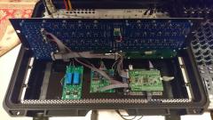
I finished my build today, turned on my SeqV4.... some LEDs lit up, and there are solid top rows (black bar) on the LCD displays. There is a red LED flashing on the STM32F4. What's going on? I built my core and tested the discovery board months ago with LCDs attached. Successfully set up, read SD card, screens displayed as expected. I haven't turned on the core since then as I've been focused on enclosures and other aspects of the build. Now today, I assemble the enclosure with my CS board, two MIDI I/O, one Quad IIc, and one Line Tx. I removed the USB Power jumper and connected this 5V DC/DC converter that was recommended to me by another SeqV4 builder https://www.adafruit.com/product/1385 The AC adapter I used was 7.5V/2A. When I turned it on, I got the results described at the top of this post. I powered off, disassembled, and tested the output of the converter which measured 5.27V. Next, I replaced the USB Power jumper, disconnected all peripherals except the LCDs, and powered up using the USB port. Same result, core won't boot. Could the 5.27V supply have damaged the discovery board? Do these symptoms sound indicative of some other failure or user error? Thanks so much for any help!
-
Thanks for your reply. The sim works fine with the configuration you suggest, but I haven't tried much on the breadboard, haven't had time and my SEQv4 and DOUT are not ready to use for testing. Part of the reason I had the LED on the emitter is because I'm trying to salvage some of the version 1 boards which already have sockets and LEDs installed, so adding a daughter board with the drivers would save me from desoldering or scrapping those parts. I had figured out a way to send signals back and forth to the daughter using existing headers, but I can't go to and from the LEDs, only one or the other. So R1 doesn't limit current in the sim above? There is certainly a change in LED brightness when changing R values.
-
-
I know this topic has been raised before, and I've read through some of those threads, but I haven't found a definite answer and couldn't find Altitude's files on the wiki to use as reference. I saw that Hex Inverter's MIDI2CV was mentioned as an example of a usable LED driver. The specs of the MIDI2CV quote a gate output of 0-5V. Some research proved that this is a common method of LED driving, and of course that there is plenty of debate about which method is best. I have designed an 8-output board based on that, but I had D0-D7 reversed on my first batch. Before I order new boards, and as I'm not an EE, I figure it's best to confess my ignorance and get some input on the circuit from some other MBHP builders here before I have these fabricated. Below is a schematic of the circuit, one instance per output. The 220Rs are already installed on my DOUT board, so I've included them in the sketch. The 33k is based on the original circuit, but I changed his 1K at the collector to 150R (based on a basic LED-resistor calculation) and plan to use some of the 220s I have left over instead...but this doesn't account for other variables (the 33k, the 3904) because I honestly don't understand the equations. Here's the datasheet for the 3904 http://www.mouser.com/ds/2/308/2N3904-1118515.pdf I tried this circuit in a simulator with various resistor values. I was attempting to tune it for Vbe saturation per someone's advice, but I don't know what I'm doing. If I change R2 to 18K, I get the following results, but I'm not sure that matches my targets from the datasheet (again, I don't pretend to have a grasp of this yet). What are most people doing for their gate/trig/clock outs? Sockets wired directly to J3-6 on DOUT with no LED or output protection? Am I totally off track? Thanks in advance for any advice!
-
Face palm. Now I see that the first link you sent goes to the kit, but I couldn't find that available when browsing their shop. I already ordered the PCB, so I'll just get the parts from Mouser
-
I only see a kit for the adjustable PSU, but I can source these parts myself with ease, I'm sure.
-
I must have been ordering from MFOS as you were posting that...but I only got the PCB, didn't realize there was a kit. I'll go back and have another look. Thanks for your help
-
Thanks Eptheca! I actually just commented on your photo before seeing your comment here. What value caps did you use? Was this just to reduce the overall height of the PSU? I'm looking for a PCB for that now, modular addict is sold out.
-
 Super work! Are you using the MFOS PSU just for the AOUT_NG? I was looking at that as an option for mine, but the boards are out of stock at the moment. You are using just one pair of bypass caps?
 -
Any of these been used? http://musicfromouterspace.com/analogsynth_new/WALLWARTSUPPLY/WALLWARTSUPPLY.php Doepfer DIY or MNT? (DIY seems too big physically and the MNT may be underpowered)
-
I'm trying to finish the design of my breakout box and need to decide on a power supply. What are some proven solutions that builders here have used? What is the max power draw of the AOUT_NG? I would prefer to maintain a low profile and small footprint to keep my breakout box compact. Thanks!
-
Hey! I was going to wait until it was finished to post it here, but no worries. Thanks, Mongrol!
-
Hey! Posting on behalf of someone waiting for access to the forum... wondering if there is a SeqV4 user in the UK who's willing to meet up for a demonstration of the user interface. He has a good idea of what is possible with the device, but as he is legally blind, he really needs to try it himself before he can commit to a purchase or build. His name is Tim Burgess, based in West Midlands. I'm not sure how far he's able to travel, not because of his eyesight, only because I didn't ask before making this post. He can be reached at tim@raisedbar.net Thanks for anyone able to help! nick
-
Thanks for figuring this out! I had already started working from the "test" file when I received this reply from Dan at Ponoko: "Looks like the templates are causing issues in the new version of Inkscape. The easiest solution is to copy and paste the designs into a new template and then scale up the artwork by 124.999%. It should be at the right scale after that." I'm just going to continue working from "test", but this info might be useful for others
-
Hello! I'm looking for a set of Line Driver boards (or built/tested). I'm located in the US. Does anyone have some spare? Nevermind, see new for sale post