niles
-
Posts
56 -
Joined
-
Last visited
-
Days Won
4
Content Type
Profiles
Forums
Blogs
Gallery
Everything posted by niles
-
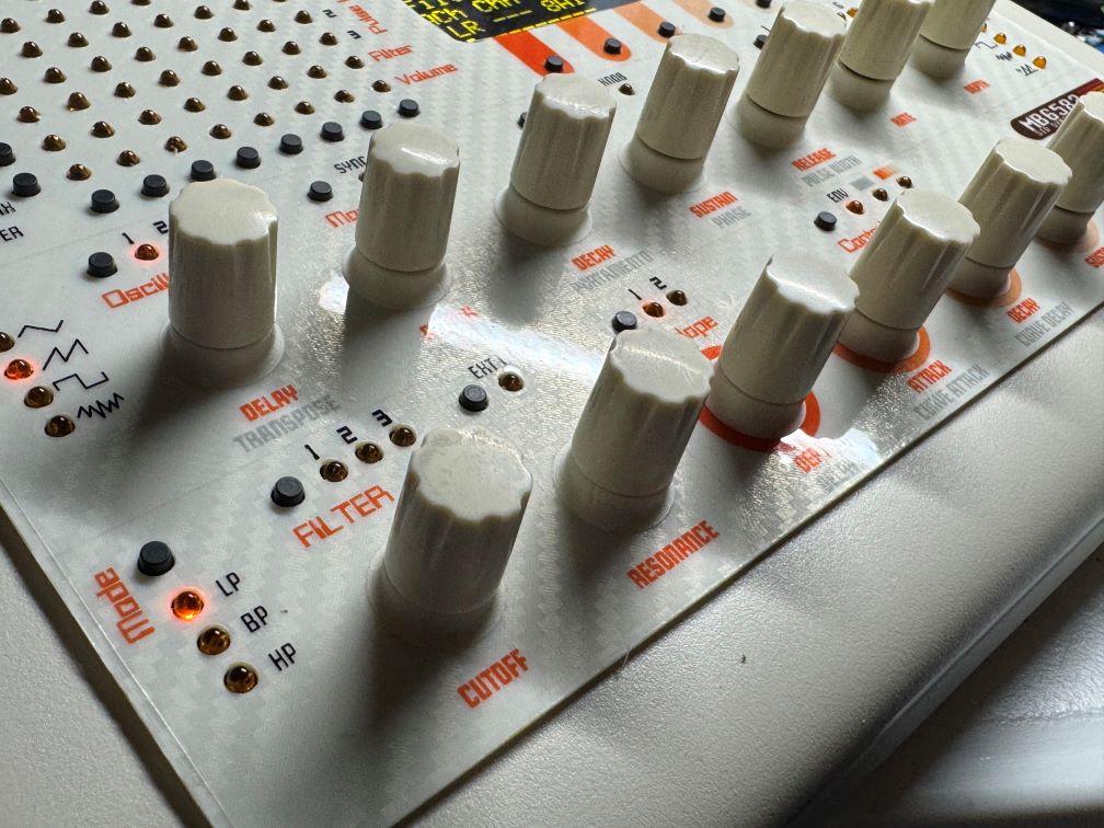
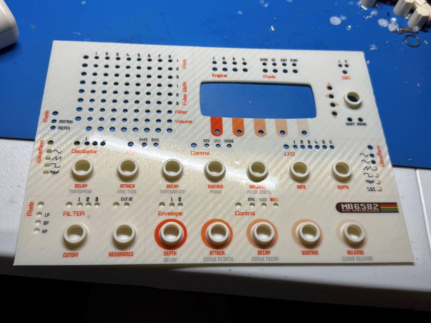
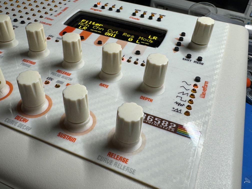
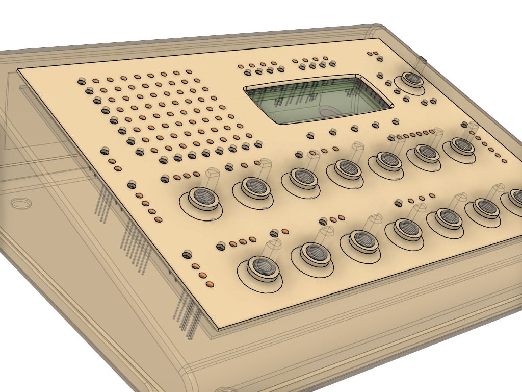
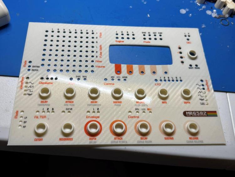
Here are the files. If someone could post them to the appropriate location that would be great as I do not see an upload function on the page that Smithy linked to. The front panel was created in inkscape and needs this font: https://www.1001fonts.com/bitwise-font.html The knob_base.stl works with Davies 1900H (and clones) style knobs. This is the only part I printed with a very high resolution of 0.08mm layer height. The rest can be either 0.16mm or 0.20mm layer height, or personal preference. The LED_spacer_standoff.stl's purpose is to hold a series of LEDs in place while soldering so they are the exact height for the PCB_spacer.stl and top_panel.stl. You can slice it in half for fewer LEDs or just print more for the bigger runs like on the mod matrix. I printed out quite a few since they are so tiny. For the top panel: 3D printed face down on a "carbon-fiber style" steel plate to get an interesting design on the top to shine through the vinyl sticker, so that was just personal preference. I printed the SVG 100% (no scale) on a color inkjet printer onto a vinyl adhesive/sticker (https://www.amazon.com/dp/B0BVMZMWCY), applied carefully to top_panel.stl and then just used an exacto to cut the holes out and trim the extra off the sides. Then placed it onto the unit, a small drop of super glue in each corner or thin double stick tape would work also to hold it in place. Then I used superglue to add the knob bases, then the knobs themselves. Hope this helps :) MB6582_STLs.zip
-
Apologies everyone I just saw these messages. I will make a note of gathering the files tonight and uploading them to the appropriate section here (Thanks Smithy). Thanks everyone for the kind words :)
-
Thank you :) Yes heat could be something that may be an issue so I will follow that closely. I took Peter's advice from another thread and used heatsinks on the SID chips, at least.
-
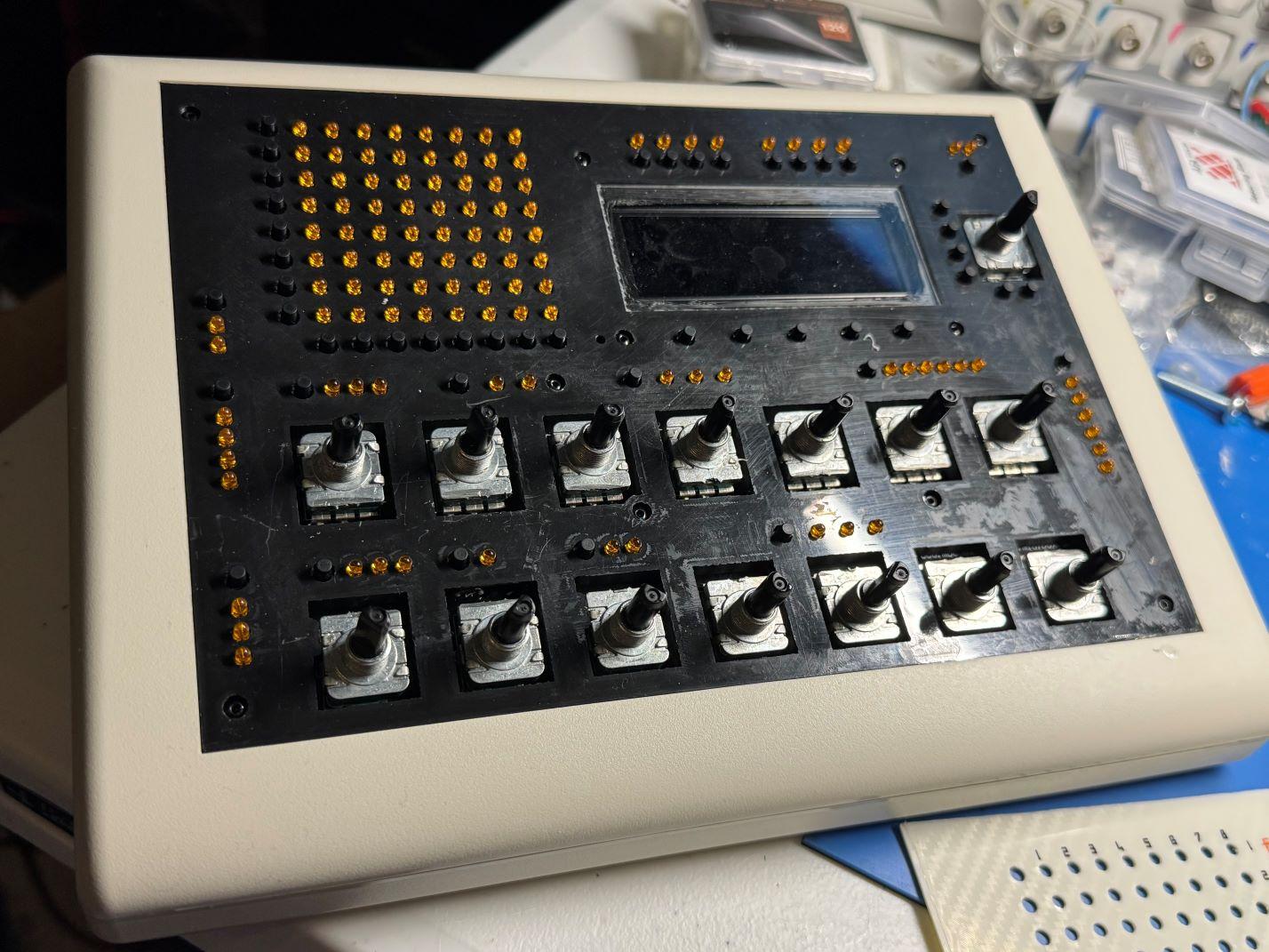
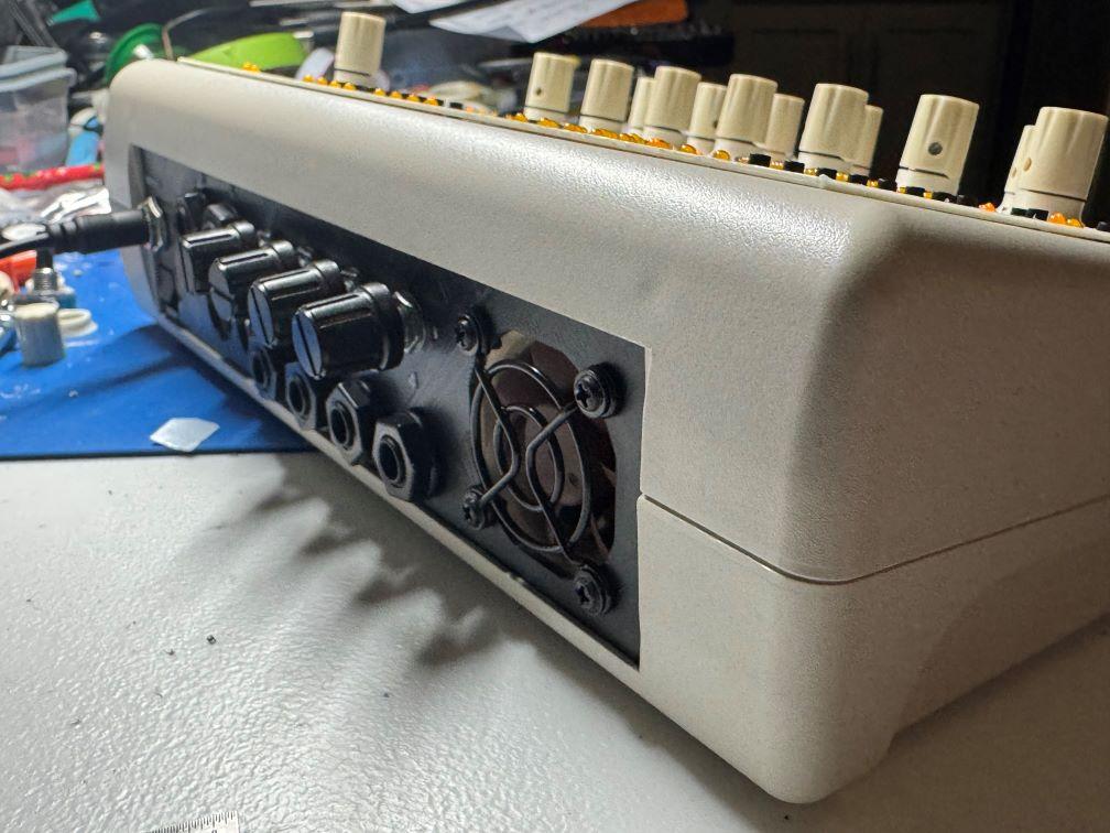
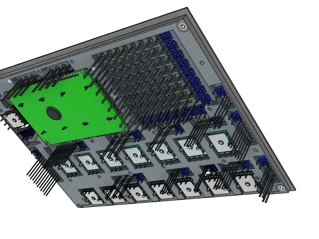
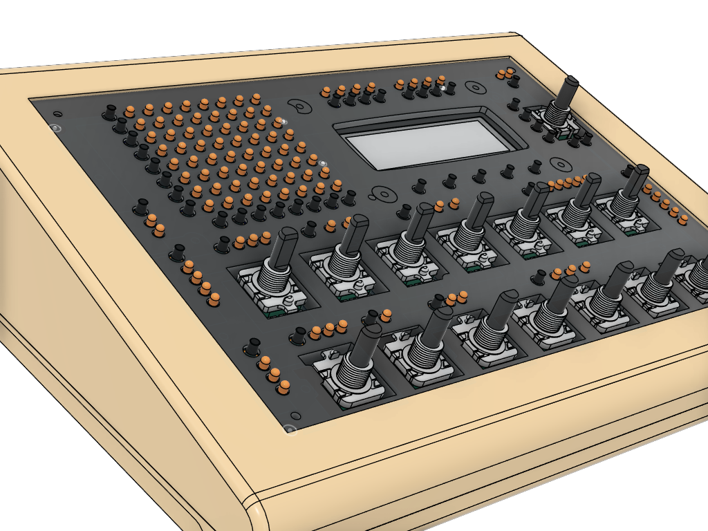
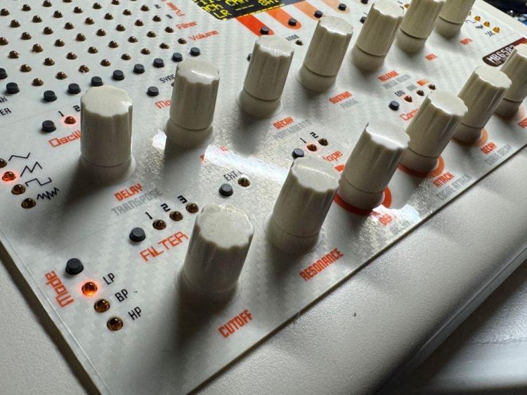
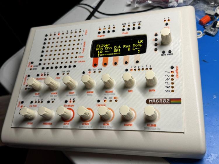
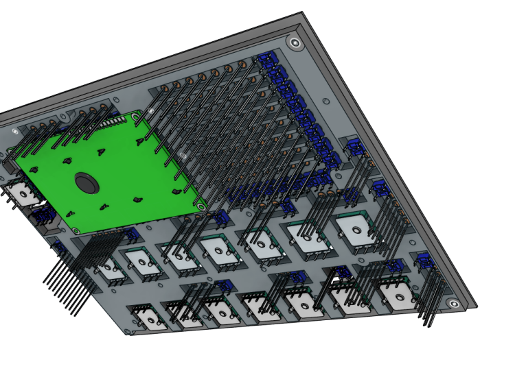
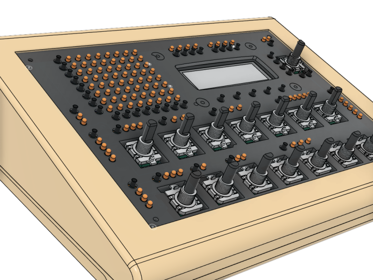
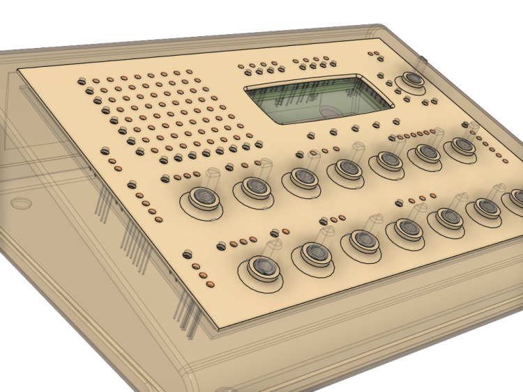
Hey everyone, just wanted to share my latest build since I'm sure there are some 3D printing enthusiasts here like myself. I bought the parts for an MB6582 about 5 years ago, if you remember Meeblip was selling those 8580 SID chips and I picked up 8 of them, and then put everything into a box in a closet . 3D printing has come a very long way since the original MB6582 was created by Wilba. I read that the JB Weld solution may or may not be holding up great after all this time. Also, I wanted to use a Newhaven OLED which is much thinner than the original LCD. I thought there must be a solution to lower the gap distance so why not create some type of spacer for between the front panel and the PCB? I designed all parts in Fusion360. The PCB screws directly into the spacer using M2.5 nuts/screws and plastic screws. The top of it has a flange that rests in the panel groove for the PT-10. Total spacer height is 5.7mm which is the height of the base of the encoders. The front panel is another 1.25mm. Everything is printed out of ASA, which is very strong and heat resistant. I designed the panel graphics in Inkscape and printed on translucent vinyl. I used Davies knobs with small printed skirts to cover up the threads of the encoders since they were exposed. I do not have a vinyl autocutter but I do have an exacto and lots of patience Overall tried going with a 80s beige computer look. A build plate for my printer created the carbon fiber effect on the panel. I'm happy to share the 3D files if anyone could use them.


-
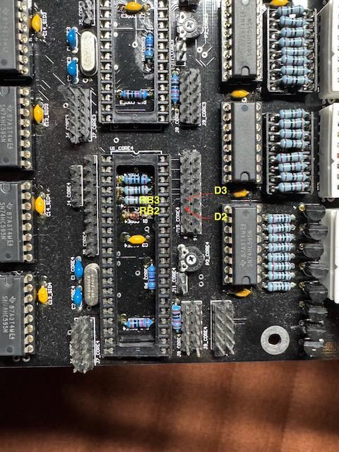
I pulled all the SID chips very carefully and still saw the issue, so PSU is fine presumably. Confirmed when I then pulled the PICs and saw 10k ohms across RB3 and Pins 11,32 of the socket and J5-Vd. Someone put a 10k for R80 instead of 1k, annoyingly... :P I replaced R80 with 1k and we have success! I guess that makes sense that the issue only manifested when all four were added. Can't thank you guys enough. I really appreciate it as always! I'll be making a separate thread eventually once I get my front panel finished. Cheers!
-
Good idea. Here's what I tested and the results are super strange: I didn't do all possible combinations but hopefully this helps, table below of what I see near the SID select buttons. If there's a *, that is saying "SIDx Not Available (No MBNet Response)". If I select a SID slot with a "-" then I can modify the respective parameters like normal, so I assume that means A-OK when there's a "-". # Core 1 location Core 2 location Core 3 location Core 4 location Display with Sid 1 active 1 PIC 0 PIC1 PIC2 PIC3 1 * * * (CAN BUS ERRORS) 2 PIC 0 Empty PIC2 PIC3 1 * - - 3 PIC 0 Empty Empty PIC3 1 * * - 4 PIC 0 Empty PIC3 Empty 1 * * - 5 PIC 0 Empty PIC3 PIC1 1 - * - I seem to be getting the CAN Bus error only when there are all four, in whatever order. Something with the master core?
-
Thanks again for your help, Thorsten. I did all the tests and everything passed. I get a diode beep only in the correct direction between RB2 and RB3, nothing in the opposite direction. All RB3s are connected, no shorts between RB2 and RB3 on all sockets. I'm not sure what else it could be connection wise...the circuit seems OK. You mentioned pulling the PICs first to test, which I did, would it damage a PIC to run a diode test with it in place? I'm wondering if somehow physically inserting the PIC into the socket in core4 could be the issue? Could there be a voltage drop if all 4 PICs are inserted or something...just grasping at ideas now. I'm using Power option E since that seemed the most modern and reliable.
-
Hi - I doubt it, I used the PICKIT3 to erase PIC4, re-wrote the boot loader, put it in core1 place and sent the MIOS OS, then the device 03 hex file. MIOS Studio would only recognize it as "3" from that point on.
-
It was mentioned in the newhaven OLED post and it was called device_id_00_lcd7.hex. I don't remember exactly where I got it in the forums but it wasn't posted in that thread. The OLED ended up working fine with it - I only sent it to the master core via MIOS Studio. If I swap 3 and 4 then I get the CAN bus errors. means it's some type of physical connection issue? Could it be around core3 since that is just upstream of 4?
-
Would you mind confirming if my picture is correct concerning the locations of RB3, RB2, D3, D2? The diagram you provided looks like all D3's on the J15 headers would be tied together, but I'm not experiencing that, and I'm thinking either something different is happening on this board or I have the wrong locations. EDIT: Also wanted to add, in case it helps, that I am running the Newhaven OLED. On Core1 I soldered the little jumpers on the bottom side of the board under the core, but did not solder them in the other cores, would that be necessary? The OLED works fine when connected to core1, I think at some point I installed the custom LCD driver I found on the Newhaven OLED post on Core1 PIC. When I connect the display cable to any other J15 header I see nothing, so I guess they are missing the custom driver, and would need the tiny solder pads jumped, although that's not probably not needed to get the CAN bus error resolved.

-
Thank you, Thorsten! Fingers crossed that one of those is the source of the issue.
-
Hi all, I'm finally at the point of 99% finished with my MB6582 build and have run into a "CAN Bus errors" issue. Here is a description of my build: 8 SID 8580 chips 4 PIC18F4685 burned by me using Pickit3 Using latest versions of boot loader, Mios OS, MIDIbox SID (v6582) available for download. I'm pretty sure it's not the PICs or software. What happened is I put master core 1 in, it works fine. Slave core 2 in, that works fine. Slave core 3 in, that works fine. Slave core4 in, I get CAN bus errors on SID2,3,4. I reburned PIC4 thinking that could work (read it on forums) and no luck. If I remove slave core3 and put slave core4 into the third spot, leaving fourth empty, then I do not get errors and just "SID3 not available". To me that means the core4 area on the PCB has some kind of issue but I can't figure out what to look for. I do not see any lifted tracks or cold joints. Are the CAN components just in the small area around the PIC socket? Maybe I'm missing a jumper or something stupid like that. Thank you PS In case any future folks read this, I originally burned my PICs years ago using Pickit3. I had a huge issue re-burning a PIC using the pickit3 since the easy standalone software I previously used is not supported anymore and Microship requires you to use this huge, unwieldy software called MPLAB X IDE/IPE which took like 30 mins to install and has a substantial learning curve. I found http://kair.us/projects/pickitminus/ It supports Pickit3 USB and worked fine.
-
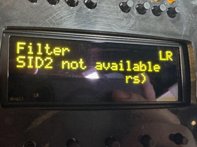
Hey all, sorry for bumping an old thread. I am putting the finishing touches on my MB-6582 and I'm seeing this issue on my OLED (763-NHD-0420DZW-AY5 Mouser) it's the Newhaven 4x20 OLED: In the photo attached, you can see the 3rd line is not showing up, it's cut off and you can only see an 'rs)'. Ignore the "SID2 not available" I'll deal with that later lol. EDIT: I fussed with it a bit more, and it turns out there is a bad connection ON the display's PCB. If I push the display together to the newhaven pcb the letters fade into view. I'm looking to pinpoint exactly where it's not working but at least it's not a software/configuration issue. Mods you can delete this post if you want. Thank you
-
Hmm..I'm leaning towards not removing the detents since 1) I do not want to risk ruining them or making them crappy, and 2) I like things with a little resistance and I heard removing them can make them super slick. I am not that concerned with resolution, as I understand it takes multiple full turns to reach limits as opposed to a pot. Thanks again
-
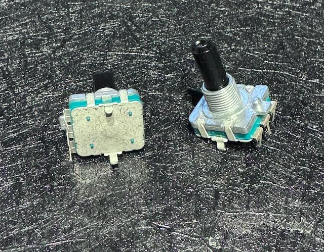
That is very kind of you to offer. I actually already have some...I ordered the Bourns a few years ago (just now getting to this project), and I'm curious if they are the kind you're using? There doesn't appear to be any marking on it, but I attached a picture of them. Just curious if maybe I should get a different type before I solder them in.Thank you!
-
Hi - About to start my CS board and looking at the instructions again...where did everyone land with the encoders now that it's been a number of years? Are the Bourns (https://mou.sr/41UDhud) or the Alphas (https://mou.sr/4ioDwop) the preferred solution? Seems like the Bourns could be hit or miss but the alphas are reliably 'no bounce'? I ask because Wilba on his page says in an 'update' that Bourns are the ones he recommends, but that page hasn't been modified since 2010 Still prefer to de-detent 14 of the 15 encoders? I know that was optional just curious how people have gotten along with them. Copying product URLs for Mouser kept giving me 404 errors, so I had to use the short 'share' links they provide sorry about that. Thank you!
-
Awesome...I'll start there - thanks for the fast reply!
-
Hi Andy and Peter - Got a weird bit of behavior from encoder #9 and looking to see what your recommended steps to diagnose would be. The encoder is showing some weird behavior - pressing it works and registers, turning it while it's pressed registers, but just regular turning it doesn't work. Sometimes after I press it it works a little bit like it's skipping around but mostly it's dead unless I'm holding it down and turning it at the same time. Encoder went bad do you think? Thank you
-
Hmm..that is good to know. Could be my somewhat modern gear - although the SL Mk2 is pretty old I think. Thanks
-
For some instruments with Midi DIN I have, but shouldn't I at least see some activity on the midi monitor under USB1, USB2, USB3, or USB4 using a usb keyboard?
-
That is awesome progress/news on the cv modules, very cool stuff! Got a quick question that I guess is more troubleshooting related than operation related - On the Midi IN4 and OUT4, I know they are planned for controlling the BLM at some point in the future, but in the meantime should they work as regular Midi in/out ports? I have a keystep plugged in and it works on IN1, IN2, and IN3, but not 4 (when viewing via midi monitor). Was curious if it's a midiseq software setting or intentionally hardwired to be different. My vote goes to bad wiring on my part, but just double checking. Thanks EDIT - Actually the more I read on the USB OTG it seems like I should be able to plug the keystep into USB with the switch in the OTG position. Quick power cycle but still no activity on the midi monitor. The same if I try with my Novation SL MK2 midi keyboard. Both they keystep and SL are being powered by a PSU and not reliant on USB power. Do you need a special OTG cable for it to work?
-

Building the MB-6582 Control Surface - Photo Tutorial
niles replied to Hawkeye's topic in Tips & Tricks
Many thanks, Peter. I got a deal on 8580s from meeblip awhile back, I'm working through PSU option E. Got an OLED screen. I'm thinking of panel mounting the switches directly above the window so I can flush-mount the screen. Probably just build my own enclosure, it looks pretty cramped in the PT-10 and I like a little more room to work with. Based on your one post about how much of a pain the flat leds are I'm thinking of just going with regular round ones. The PSU is tricky for me since Jaytee's build guide leaves off necessary components from the original Wilba build guide, which makes sense since its original intention was a retrofit but a little confusing for scratch builds. I think I can figure it out. -
Lucky 13! Thanks, @Hawkeye!
-
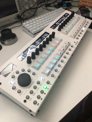
All working now - Here's my beauty Turns out I had a bad cable (my nemesis) for the MIDI8 board. I went with the red/cyan color mix for the LEDs. Keycaps courtesy of @Antichambre . Also, I went with shorter 16mm keycaps for the switches ( mouser 642-1S11-16.0 ) instead of the 19mm from the BOM, I thought those were a bit too wiggly. I had a few self-inflicted hiccups along the way but I'm extremely pleased with how this turned out and the quality and support of the midiphy kit is top notch, of course. Cheers!
-
Building the MB-6582 Control Surface - Photo Tutorial
niles replied to Hawkeye's topic in Tips & Tricks
You wrote this kind of a long time ago @Hawkeye but can I ask why did everyone used JB-Weld in the first place vs just having screws from the top? People didn't want to see the screw heads on top of the panel? Why not use the encoders to attach the front panel? Looks like there is room to lower the panel a few mm - was the height dictated by the original LCD height? Apart from the flat-top LEDs being a bit of a pain, anything anyone would do differently with their build? I've read all the big threads and really studied the wiki pages. Looks like an exciting project!