SimonSays
-
Posts
53 -
Joined
-
Last visited
-
Days Won
5
Content Type
Profiles
Forums
Blogs
Gallery
Everything posted by SimonSays
-
Hey all I've just completed my Seq V4+ (what a beast!) and enjoyed the quality of the code, platform, hardware, community AND this video that I really want a SID V2 now. I'd like to jump straight into the 6582, but happy to be persuaded/dissuaded. TK's guide is detailed and helpful, but I've got a couple more questions: * I can see that the boards can be purchased at Modular Addict - this is workable, but does anyone know of any EU suppliers?; * SID chips - aside from wishing I hadn't given my C64 and Vic20 (!) away years ago, getting hold of chips seems very hit and miss on eBay. Any advice on where to/not to go which variants (6581, 8580, SwinSID Ultimate, are revisions important, etc. - I think I understand they can be mixed as long as stereo pairs are matched?) - or if anyone here is looking to sell any! - gratefully received; * Further to above - can SID chips be tested, in the circumstance where I start buying them on eBay and don't have a C64 or SID synth to test them in? * Case: can the Wilba cases still be had? I'm pretty happy with acrylic cases, so if there is a set of CAD files I can have one made... Many thanks, Simon
-
Sorry - I was trying to be efficient, but I hijacked the thread... I'll create a new one and repeat the Q. Thanks (and the answer - that is what I was asking!)
-
Oh - and scrub the question about design files for case... I found them on the site! :)
-
Thanks @Noise-Generator... dirty + more bass is obviously good, but £50-80 per 6851 is going to push my bill pretty high! I think I'll get the Wilba PCBs from Modular Addict (unless any EU suppliers get mentioned) - it's the Control Board + The Main Board, right? I like the idea of starting with a pair of SwinSIDs and going from there. Can I build a quad core if I'm only using two chips - or do I have to match 1 core to a stereo paid of SIDs (if I want each pair to be independently addressable)? From there, I suppose a pair of 8580s and see how I feel about the next pair!
-
Hey all I've just completed my Seq V4+ (what a beast!) and enjoyed the quality of the code, platform, hardware, community AND this video that I really want a SID V2 now. I'd like to jump straight into the 6582, but happy to be persuaded/dissuaded. The doc above is great, but I've got a couple of questions: * I can see that the boards can be purchased at Modular Addict - this is workable, but does anyone know of any EU suppliers?; * SID chips - aside from wishing I hadn't given my C64 and Vic20 (!) away years ago, getting hold of chips seems very hit and miss on eBay. Any advice on where to/not to go which variants (6581, 8580, SwinSID Ultimate, are revisions important, etc. - I think I understand they can be mixed as long as stereo pairs are matched?) - or if anyone here is looking to sell any! - gratefully received; * Further to above - can SID chips be tested, in the circumstance where I start buying them on eBay and don't have a C64 or SID synth to test them in? * Case: can the Wilba cases still be had? I'm pretty happy with acrylic cases, so if there is a set of CAD files I can have one made... Many thanks, Simon
-
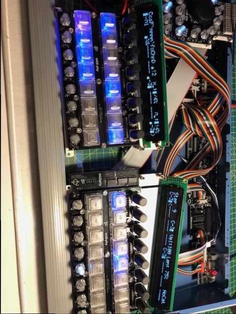
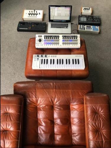
Ladies, Gentlemen... it lives! And what a handsome centrepiece it makes in my little music den :) I couldn't wait to do anything like read the manual so I've jumped straight in to produce some basslines out of my Shruthi XT. Big wide grin on face! Thank you Peter @Hawkeye and Andy @latigid on for the help with the build and troubleshooting. I think I had a couple of small problems that were only cold joints but identifying and finding both was tricky and I would still be swearing at it without you. Obviously thanks to Thorsten @TK. for the design, code, etc. I've got a lot of gear to plug into it - thank goodness for 8 MIDI ports. Next steps: a BLM and a SID V2 :) Cheers!
-
Thanks @Hawkeye and @latigid on... That's almost certainly right re, the WS board pins and the Core headers. I realise it wasn't the WS board USB itself that was affecting the power, but the point at which pressure could be applied to turn the red WS board power light on and off was oddly specific! I've done some microsurgery on the pins and managed to achieve stable power this AM but I may put some shorts around the +5v and GND as redundancy as well later. Thanks for the tip on testing, Andy - I'm no electronics expert and I hadn't put 2 and 2 together with the Cap charging and momentary continuity. It's all good learning (for me)! I'll let you know when it's producing beats :)
-
The Waveshare board settings are as per... after another 2 hours I've localised the power issue to (I tihnk) the Waveshare board itself. I've replaced the SD ribbon connectors now, removed and resoldered the SD card header and the power is still intermittent (basically it works out of the case, and as soon as I put it in, it stops working again). I've eliminated shorts and can now see that the power only connects if I put moderate pressure on the USB socket on the WS board itself. The board is connected as far as it can onto the core (the pins are too long for it to be flush header to header, but it definitely won't go further), there are no shorts against the bottom of the case. What can be causing the power to intermittently connect/break based on pushing on the WS USB socket? While it's out of the case, I've managed to get both OLEDs working - basically, by reflowing the entire core. It's driving me nuts today!
-
Oh dear - this is now going very much not according to plan. Having just checked all data lines through the 595 and back to the MCU, all header pins, etc. I put it back together and it's now completely unresponsive. No green light for power, no nothing. Changed USB cables, still nothing. Wave board is responsive to it's own USB input power.
-
R33D is labelled as 561 - tested (in situ, no power) at 531.5
-
Following on from the above, reflowing R33D has made changes. I now DO have 3.3v on the headers at the E pins and RW pins... but still nothing at the RS pins. No short between E pins. I've traced continuity all the way from the MCU pins to the headers. STILL nothing on LCD #1!
-
Thanks! I updated the post above with some continuity checks... but not as far back as the MCU so I'm doing that now.
-
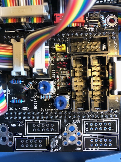
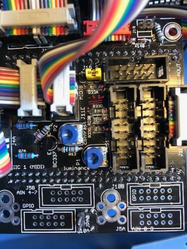
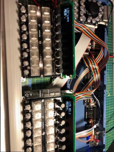
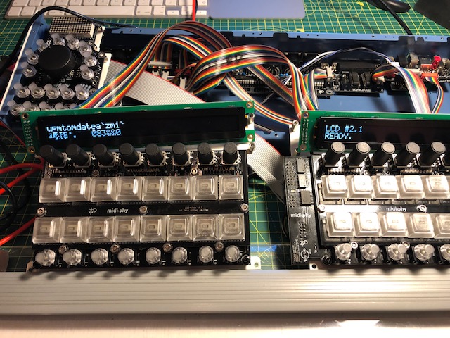
I'm getting some confusing (to me) readings here... images attached. Measuring the noted resistors above, I'm getting -3.3v grounding on left/+ve on right, as per image. On the headers, when I ground to Vs, I'm getting ~0.1 - 0.15v on both E, RW and RS pins. Hmmm... have I measured this wrong? If not, how is the R/H OLED working? I've already ruled out issues with the OLEDs/screens - either screen works perfectly when plugged as LCD#2 (R/H). I've checked continuity between: PC8/9 on the Wave board and the E pins in the headers (all good); PC11 and the mirrored RW pins (all good); PA8 and the RS pins - no continuity. So.... I reflowed R33D, got continuity between PA8 and RS thinking that I had the fix.... and no change :(

-
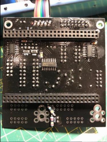
Couldn't resist some probing! Plastic inserted between OLED pins and headers for surety (no difference, though). Reflashed bootloader and ran LCD commands... that put some gibberish (some correct characters) on LCD#1 - ie. the problem one. Reflashed Seq and got something on LCD #1 on first boot but blank thereafter. Even with gibberish on LCD #1, LCD #2 was still swapping to display the actively parameters, as before. Continuity as expected on all mirrored pins EXCEPT e pins. No connection there. I got a limited continuity beep (single pip, 0.303 on screen of DMM) for the adjacent pins to the top-right and top-left of J15A and B (as picture them below) - I think this is actually top left and right on the schematic. I'm jiggered if I can see a short, though! So not sure how to interpret this. Images attached - can't see any shorts/bridges under a loupe... I can reflow the board tomorrow, though.


-
@latigid on Sorry - ignore pins question above... I can see the notches on the schematic :)
-
Thank you @latigid on and @Hawkeye... given the behaviour with the one screen being shared I'm going to guess at bridged 'e' lines and/or a config issue (the former most likely). I'm at work today and at an event tonight so I won't get the chance to troubleshoot more until tomorrow evening... but I'll have received my extra shipment of 5x2 headers and plugs by then so I can clean-up those cables as well. I'm pretty sure the Wavemaker is seated as I've done it twice and my palms are a map of the cut pins on both sides as it's a good friction fit! @latigid on - just to check on theJ15A/B pins, mine run top to bottom as I sit in front of the Seq... is pin 01 top-left, or bottom-right? Thanks!
-
I've looked at the schematic (I'm not good at reading them, so take analysis with a pinch of salt!) and checked voltages on the J15A and B headers... when grounding to bottom left pin as I look at the core board installed in the case, I get 5v on the bottom right pin, 3.3v on the top left and nothing significant on top right (very slight negative voltage). Exactly same on both headers. I have a scope, but no digital analyser so I'm not sure I can sensibly read anything from the data pins but I can certainly give it a go. I've got correct readings on all the Res to the left of J15B. The contrast pots are doing nothing but I assume that's the nature of the OLEDs?
-
Correct R33D installed, cables and OLEDS both functioning correctly - whatever is plugged into J15A - left-hand screen - shows nothing. The seq is functional - the R/H screen swaps top show whichever half the encoders have been moved for (ie. if I moved encoders 1-8, it shows steps 1-8... if I move encoder 9+, it shows steps 9-16. I've reflowed the J15A header - there was a bit of resistance on one pin - but it's made no difference... Any more for any more?!
-
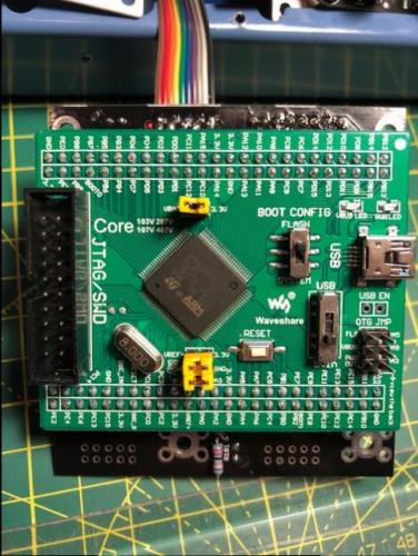
So neeeeeeeearly there... Remembered the 3.3v jumper on the core, put everything in the case (Adrian has done a great job here - built like a tank!), flashed Seq with L/H config and... the right OLED works, the left was gibberish. Rebooted and the left was blank. I'll check all the connections, but I found an old thread talking about screen issues with low and/or noisy voltage. Is this still a problem? Could it be the 3.3 vs 5v at the board? Or a need for a cap? Cheers!
-
Took the sandwiched boards apart and gave all the encoder pins and legs a flush trim and no more light show :) Getting pretty excited for the last stages and finish line now :)
-
Still on _NG... I'll check it out tomorrow. Wife is grumbling :) Thanks for the help!
-
I've got J4B on Core board soldered... in my defence, so does Peter in the video (and if Peter said "jump off a bridge" in the video, I'd be jumping, obviously :) ) No drama - I used some un-shrouded double-row pin headers on the R/H Le Mec, for the inter-Le Mec connection,. I also used a bespoke (read: created from 10 pins of socket-to-socket breadboard connectors) cable here as I will also be short 2x 10 pin 3M connectors due to my bad cable above. I can replace these once I've sourced new 10 pin IDC parts. The good news is it all works (cables and connectors, anyway) as the Le Mec testing stage is almost 100% good! The only issue I can see on that test is thaat the 4th encoder along on the L/H board causes a proper little light show on the JA MEC switches when turned/pressed + turned - also one of the encoders on the R/H board did same but only very briefly and I can't reliably replicate. I'm expecting this to be some soldering reflow required on 165 and/or 595 ICs on both boards? (Although the light show might be a standard feature?! I haven't read the manual of watched further into the video yet) Everything triggers MIOS logging - including the Matthias Switches...
-
I'm just putting the IDC shrouded headers on the Le Mec boards and I think I'm one 10 pin header short... I've checked and the BOM I copied had 17 of them, and there are 18 required on the boards (I'm not including the lower ones on the core or J89* on the larger Le Mec). Hmmmm.... Is there another part I can salvage from to get the Sequencer working this weekend? Can I exclude one of the line driver boards to begin with, perhaps?
-
It was a shorted ribbon cable... all working now. Onwards and upwards!
-
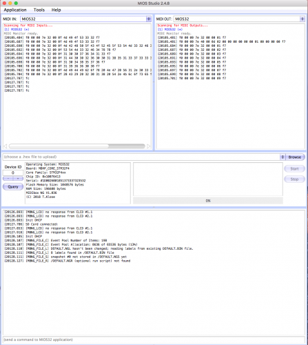
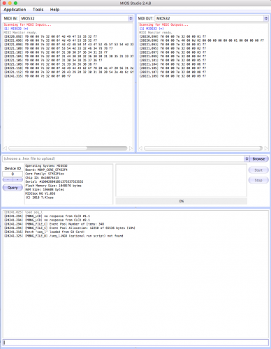
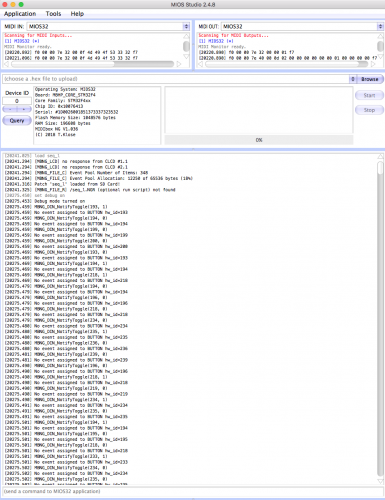
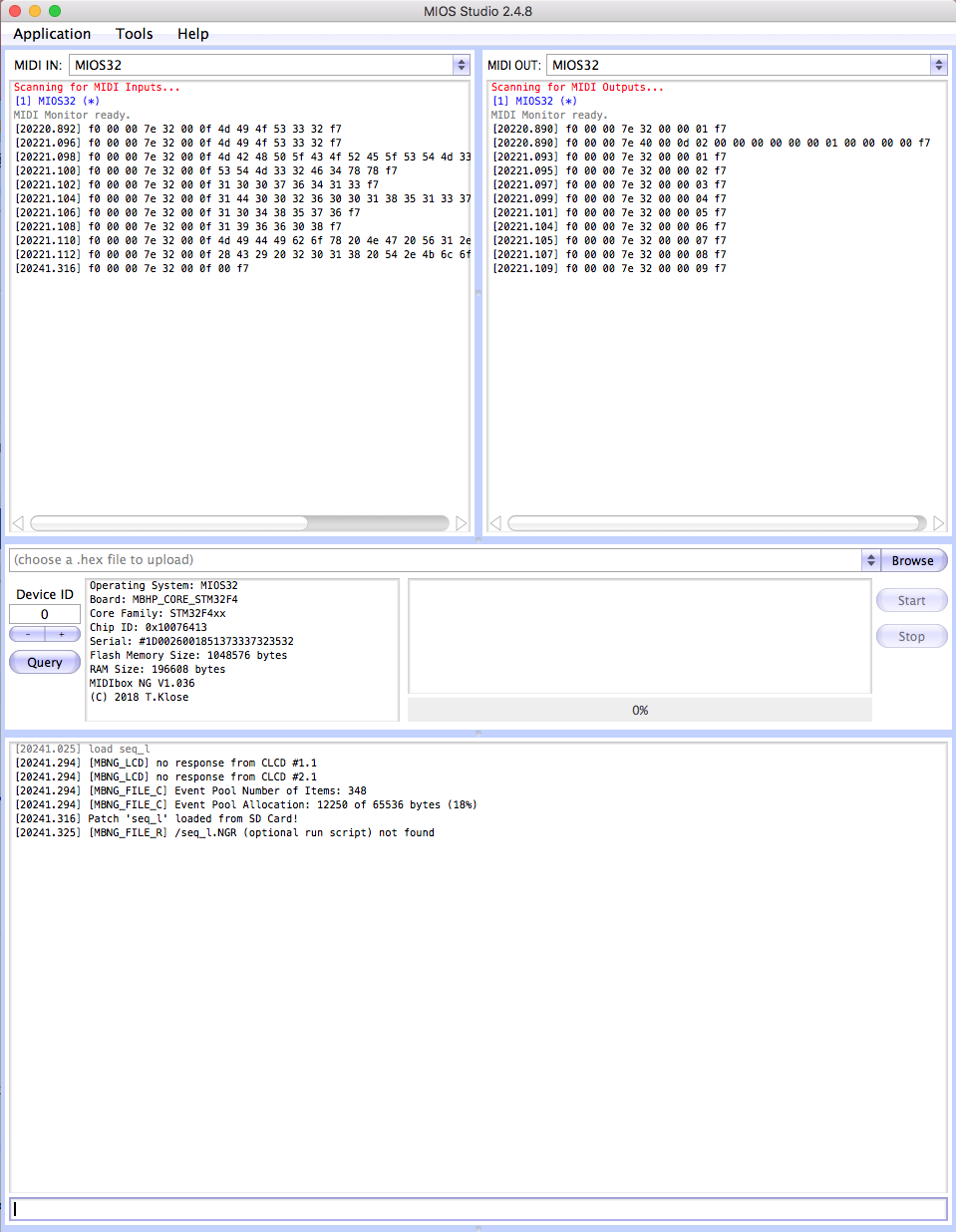
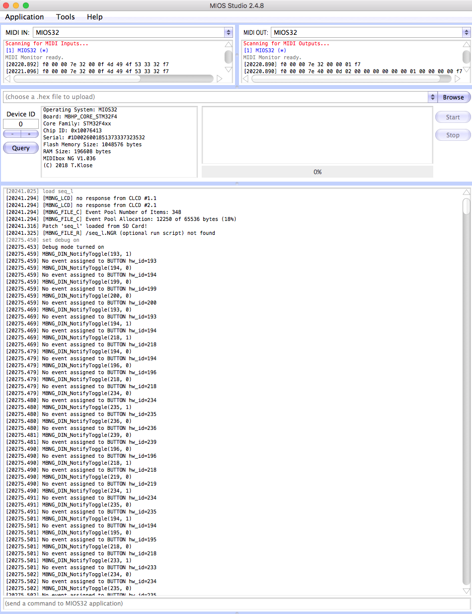
Thank you @latigid on... You were right: insufficient attention paid to filenames on my part... I still had midibox_seq flashed, rather than midibox_ng. Going back to the tutorial and flashing NG has solved part of the issue. I've got the 2-103 resistor network soldered (ie. not one of the the 1-103s) - I think that is the correct (bussed) one? I'm still not quite there, though - when I restart MIOS studio my midi ports are *not* named Midibox NG (as per Peter's video_ but still called MIOS 32. Not a problem in itself but possibly a symptom. The various .NGC files are being created on the SD card on boot, but I'm still getting some errors in the logs (attached) - some of which look like missing LCD components which is expected. But I'm not getting any response from JA board buttons and, with Debug set to ON in MIOS Studio, I'm getting continuous logs on missing events, etc. (Images below in order of the process)