

knochenfabrik
-
Posts
29 -
Joined
-
Last visited
Content Type
Profiles
Forums
Blogs
Gallery
Posts posted by knochenfabrik
-
-
12 hours ago, latigid on said:
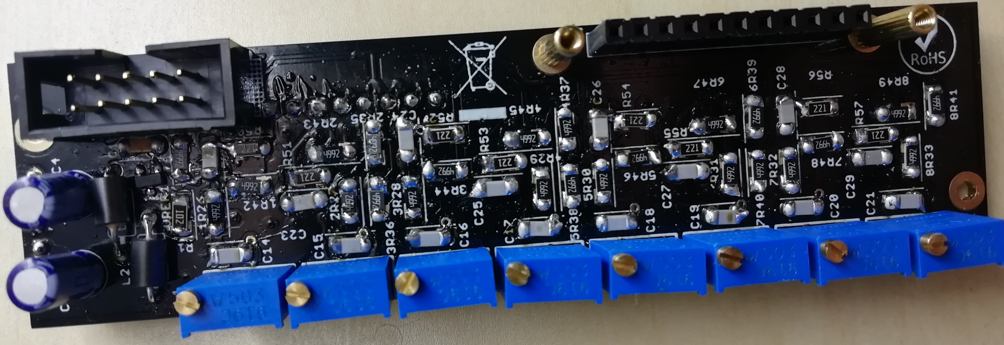
Any luck on reflowing the components I mentioned? From the behaviour I would guess 8R49 or R57 are not properly soldered.
Unfortunately not - something strange is going on here...
-
Hello, again, I measure 0.01 V on R57 but no pins of the mentioned parts seem to be connected to ground. PIN 3,5,10,12 of IC4 are connected to ground (same for IC1 to IC3) though. Greetings, Alex
-
On 1.9.2019 at 11:18 PM, latigid on said:
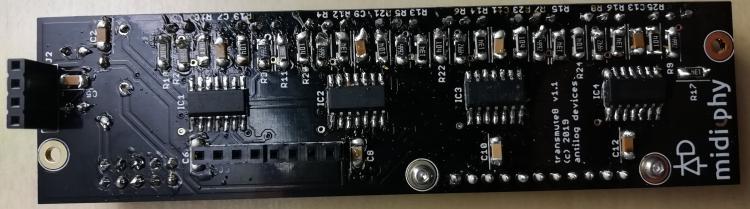
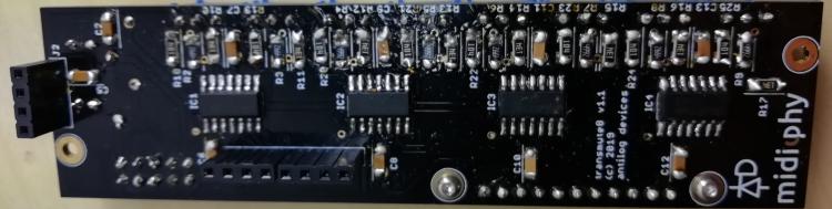
For testing tranmute8, you can start with no other boards connected. Verify no shorts on the power rail, though if your rack powered up that's likely not an issue. After connecting the Eurorack power cable, you should measure +12V/-12V on pins 4/11 of the op amps. Check that the op amp orientation is correct with pin 1 near the IC1/2/3/4 label. C3/4 seem to be correct.
I think you should still get some output even with nothing connected to the op amp inputs. Outputs on J3 should each be at -5V.
You can verify your octal board with a working binaire board.
Made some progress and got 7 of 8 Channels on the AOUT-expander working by replacing all the cables involved
 . However, Channel 8 still wont output any Voltage and the LED keeps dimm. I already tried to switch to another octal board but the issues stayed the same. Hopefully I'll find the failure soon - are there specific pins on the ICs that could cause channel 8 not to work? Thank you for the help!
EDIT: I disconnected all boards from the transmute board an powered it. On J3 i only measure -0.08 V on the 8th PIN (if counted from the top) - all other pins give ~-5V as you stated earlier. So i guess I come closer to the problem. :)
-
Yes, I have configured everything as shown in the manual. The configuration doesn't change the outputs though. LED 4 and LED 8 seem to do strange things on the AOUT-expander - first they both were dimmer than all the other LEDs and during testing LED4 even turned red...
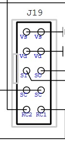
Maybe my cable is the problem: Tried to measure contuinity from the end of the J19 cable to GND and Vd on the LEMEC boards but it didnt work (used lemec since I cant reach the core-board easily). On the Core-board-schematic it shows that both rows of the J19 connector should have GND and Vd but I couldnt even find contuinity between the rows at the end of the cable that is connected to J19

-
I tried to use all of the AOUT-configs available in the system. I guess if I select AOUT Chn 1 in the Event-Page there should be uncalibrated CV on Channel 1 of the DOUT to begin with if i send Notes/Steps? However, I dont seem to have any output right now. Also, I observed that LED 4 and LED 8 of the DOUT-board are slightly dimmer than the other ones.

Attached some poor pictures - I will try to take better ones if needed when there is daylight again.
Thank you so much,
Alex


-
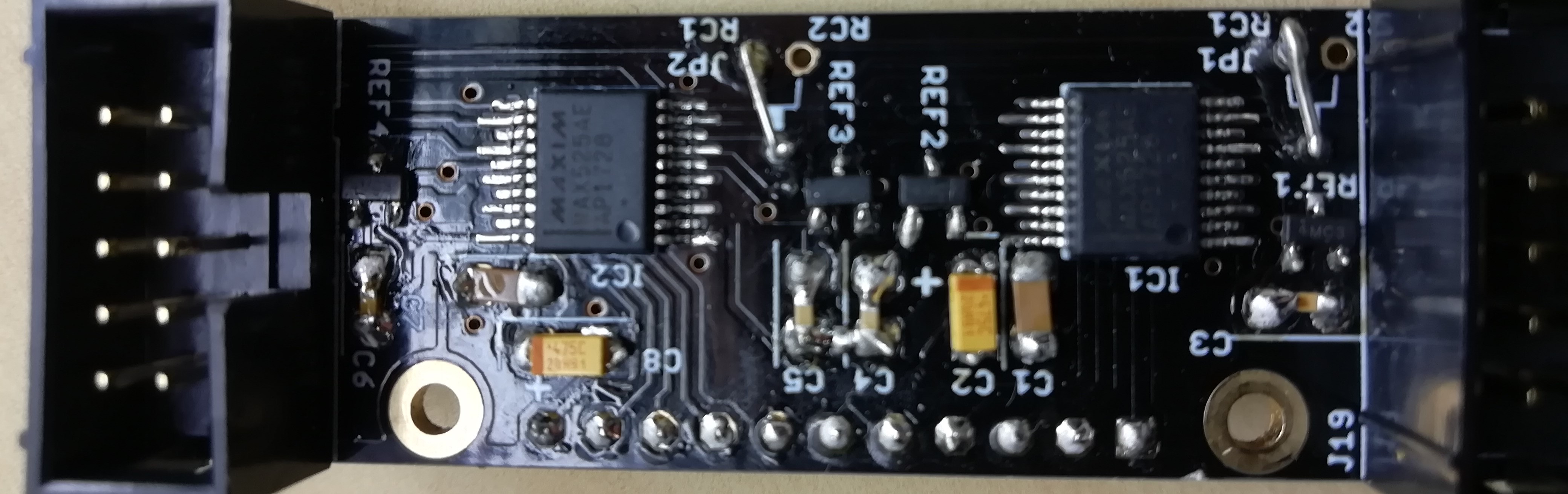
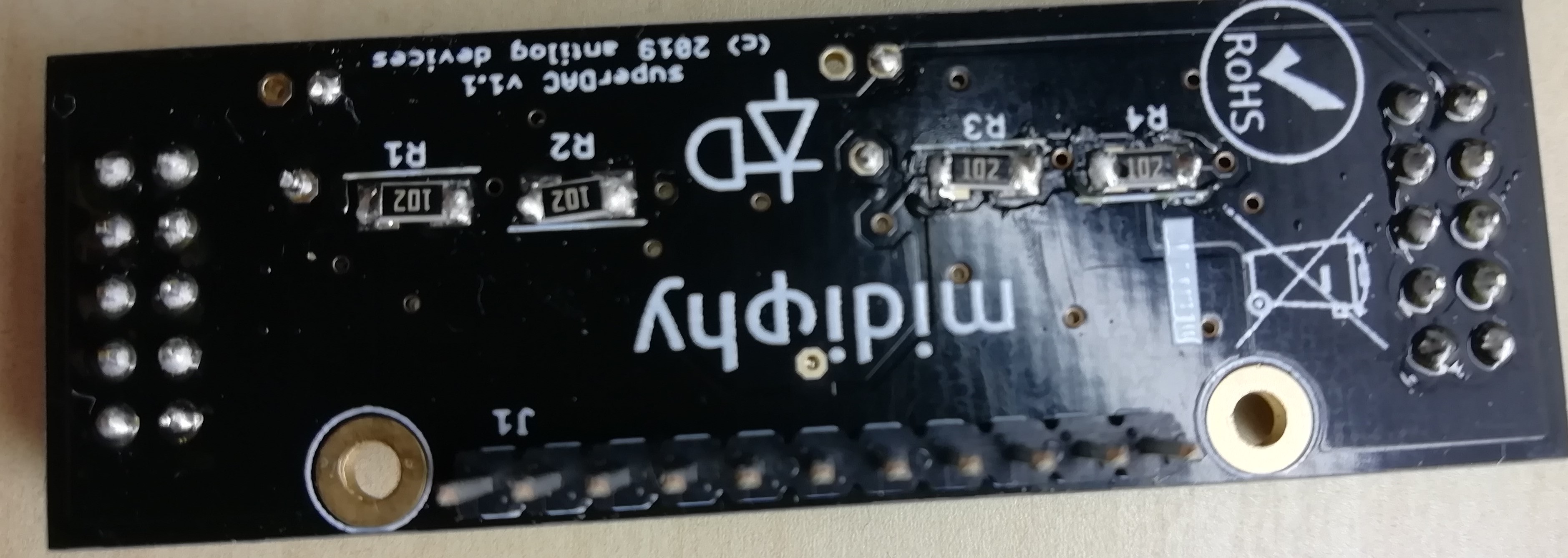
Thank you very much, after the configuartion the DOUT works fine :-). Not so the AOUT though - I cant seem to make it do anything. Should the LEDs of the AOUT be lit up when nothing is sent? I use the midiphy-pcbs but replaced the MAX5500 with MAX525s since they had the same format.
Greetings, Alex
-
Found the issue - had the connector from J8/9 to the Expander in the wrong polarity on one side. Now the sequencer starts up just fine with the DOUT and AOUT connected. Now I just have to find out how to use them. Just switching to AOUT on the Event-Page didnt do anything so far. Dont I have to configure the HW file for the DOUT? Also, is configuartion for the AOUT needed? I read in the manual that CH 1 to 16 should be allready routed to the DOUT but it also doesnt seem to do anything. When idle all LEDs are lit up on the AOUT, on the DOUT nothing lights up ever.
Thanks in advance,
Alex
-
17 hours ago, latigid on said:
Directly connected means no line transmit board? How long is the cable?
What happens when you unplug J8/9 from le mec_R?
Are any ribbon cables improperly assembled (shorts etc.)?
Can you exit this menu?
Do you notice strange DIN events with MB_NG loaded?
Yes, there is no line transmit board involved. Cable length is approx. 30 cm. When i wiggle the cable out of the J8/9 while running, the sequencer changes menus and stuff on the screen by itself - if i deattach the cable completely i can use the sequencer just as normal. Which leads me to the next suggestion to check the cables which i will do now. Lesson learned: Debuging should be caried out before reassambling the whole unit

-
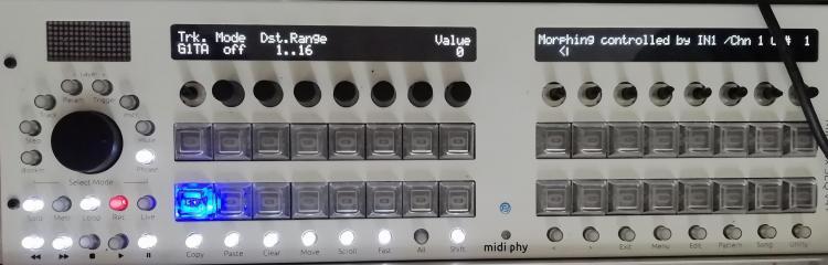
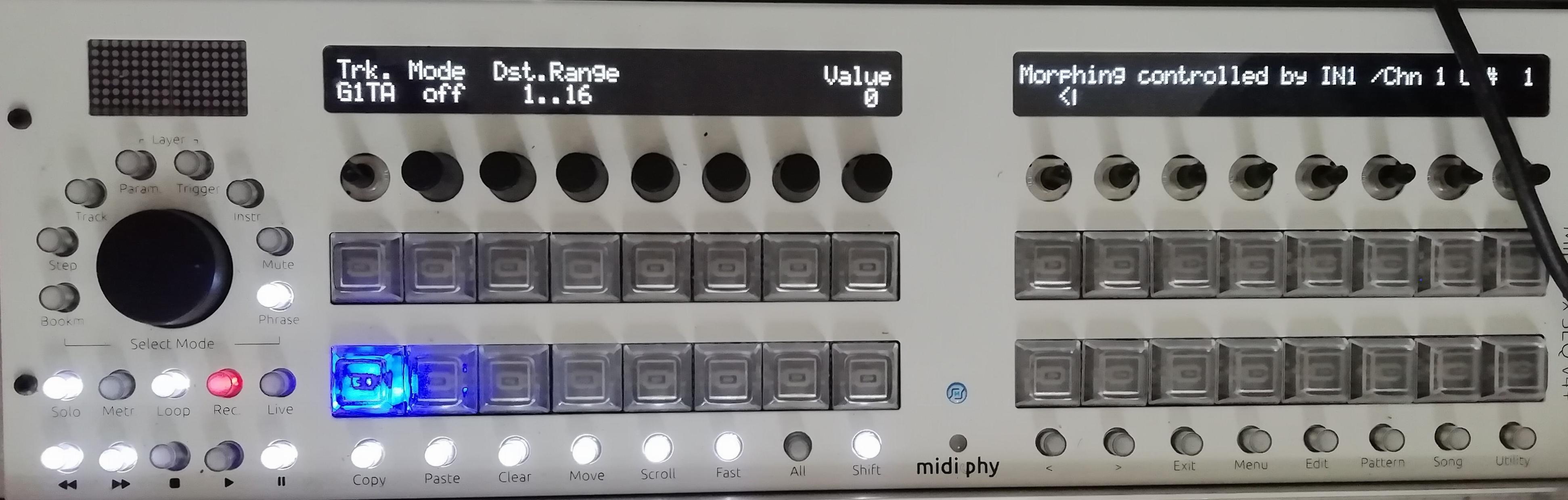
Hi guys,
just finished my DOUT and AOUT modules. J8/9 goes directly from the LEMEC_R to the DOUT-module. When I turn the sequencer on it shows a strange menu (see picture). Do I have to conifgure something to use the module first or does this more look like a hardware issue?
Thanks in advance,
Alex
-
Hello,
I´ve just received two samples of the MAX525 and now I am wondering if the new Aout will be based on those chips?
Additional question: How could I add "activity" LEDs to the Aout that utilizes the MAX525 on Ucapps? Just attach them parallel to the individual Jacks?
Thanks in advance,
Alex
-
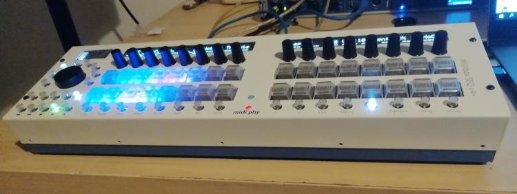
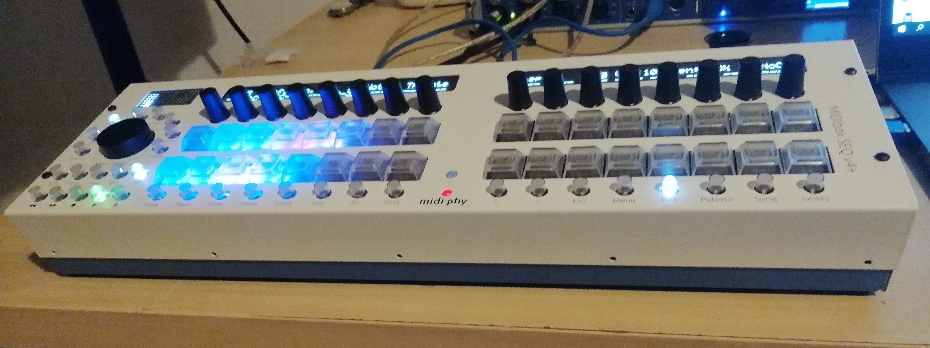
7 hours ago, latigid on said:
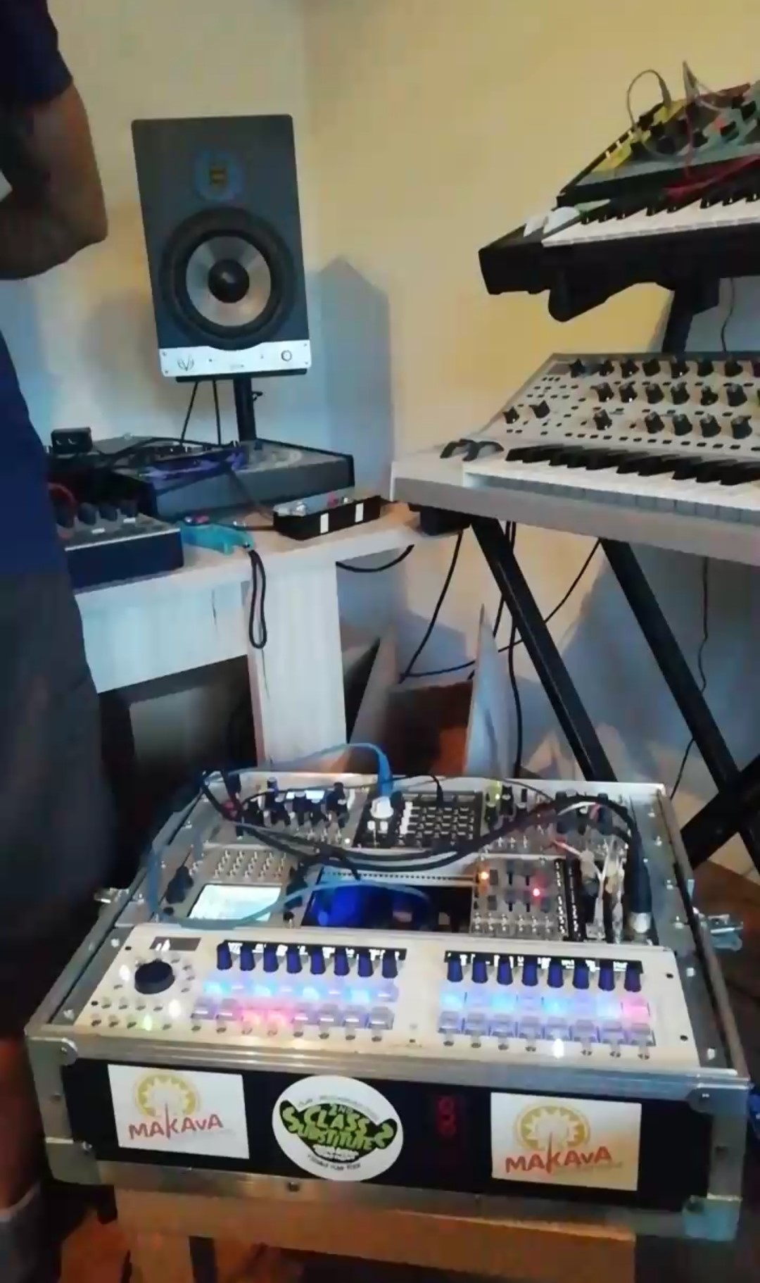
Well that's an awesome photo! Presumably you had to remove the rails/threaded inserts? But sure, everything should fit in 3U. There's been promise of ears for 19" rack mounting for a while but those are still on the way.
Not long until the modules are ready. But summer holidays can result in a slowdown sometimes.
Btw. with everything in the case like this, probably you wouldn't need to use the line drivers at all. Just connect J8/9 and J19 to the respective digital and analogue expanders.
Actually you are right - I had to remove the rails and inserts of course (ur just use none). Got that wrong in my mind when I said they stayed insied earlier...

-
Could I just remove the Line Transmitter completely and use IDC cables to go directly from J8/9 to a DOUT board and J19 to an AOUT-board?
-
Just now, latigid on said:
Well that's an awesome photo! Presumably you had to remove the rails/threaded inserts? But sure, everything should fit in 3U. There's been promise of ears for 19" rack mounting for a while but those are still on the way.
Not long until the modules are ready. But summer holidays can result in a slowdown sometimes.
Btw. with everything in the case like this, probably you wouldn't need to use the line drivers at all. Just connect J8/9 and J19 to the respective digital and analogue expanders.
The rail and threaded insert stayed, I just left out all the screws that go in at the front and at the back of the SEQ4+ case, but there actually would have been enough space to let them in and still fit I think (its just easier to fit this way).
Not using line drivers sounds very interesting, I`ll have to look into the expander-thing more to get what you say, but thanks for the information :-). -
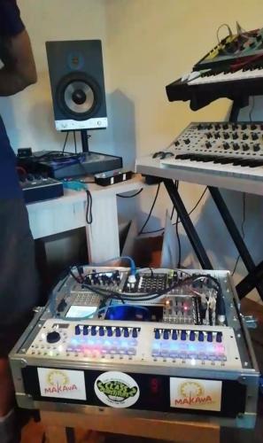
Hello guys,
I dont know if this fits here but may I ask if there is any news on the Eurorack Expander Modules?
Also, here is some bad-ish foto of some studio action. The midibox-case fits really well into 84hp and powers well from the 5V source of my Intellijel PSU. Just in case if someone was wondering if the SEQ4+ is suitable for modular case installation. I am using standard 40x20x2 aluminium angles for the rack mounting. Next step: Re-open the case and install the missing jumper for USB OTG :D.
Greetings, Alex
-
 1
1
-
-
Number 17?


-
1
-
-
On 6/23/2019 at 10:41 PM, latigid on said:
Hmm, 2000 posts
How is pin 1 bodged? Do you measure +5V to it? I would bridge to the empty J89 socket, pins 3/4. You can see the wider trace to it in your image.
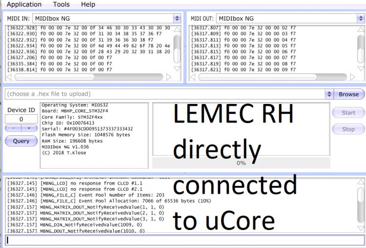
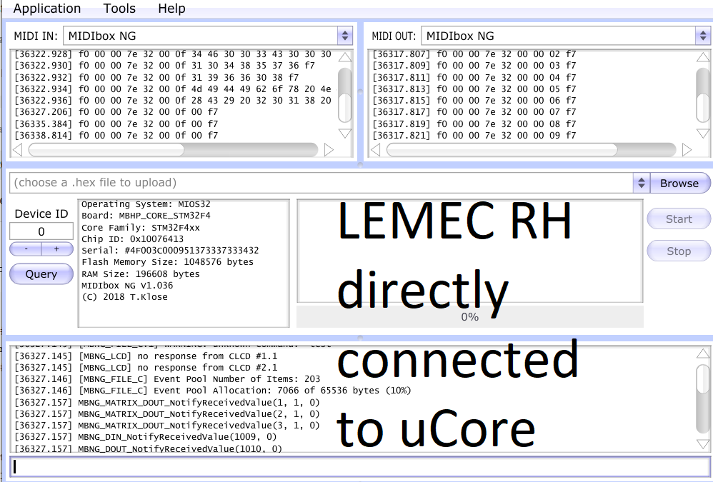
Hello there, I know this may not be according to the DIY spirit but I rebuild the RH Lemec from scratch and got it working :-). Will still try to bring the other board to life with your tips and will report on that so at least other people could profit.
I´ve already did all the assembly and tested everything in midibox NG. Also the Final Software seems to work fine. But I got one question regarding the LED-Matrix: I only see LED-Matrix working in a mode where I see the Volume of the Triggered Steps (like the peakmeter on a mixer) but I cant seem to got the other mode workingm where you can see steps relatively to their position (as shown in the build video). Do I just miss some configuration or is this maybe a hardware problem?
Thank you again for your help!
EDIT: Congrats to 2000 posts!!! Have a beer for celebration :D!
-
@latigid on Hi, I did swap cables but it didnt change anything for the better. Suddenly also de Leds on the JA Pcb started to flash randomly O.o. So maybe the cables are the reason but with only the Lemec LH connected they work fine and dont do anything bad (will check them again).
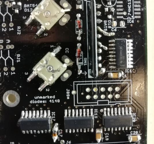
Here are some pictures of the ICs. For IC 1 i had to scrape the protection away because i removed the pads (rings) on 3 pins of the resistor network (Pin 1 (dot) ,5 ,7)
Will check the parallel inputs on IC3 now but its so strange that suddenly the JA board leds begin to do crazy stuff :) pretty confusing for a noob like me :D
Thanks for your help - will definitely have to tip you some beer when I have finished this beatuy - already learned a lot about this project...

-
On 6/20/2019 at 11:00 AM, latigid on said:
Unmodified _L should be used when JA is connected on the left. Unmodified _R should be used when JA is on the right. Modified _R should be used when lemec_R is the first board in the chain. You can of course freely modify the .NGC files to suit the configuration.
Pin 1 being the dot marker? The resistors should connect in parallel to the common pin. You should also measure about +5V on the 165 inputs and they shouldn't be shorted together.
IC17 should be connected to power. There are two larger plated through-hole vias that you can consider using.
I actually resoldered IC1 and IC17 IC18 very carefully and after that the Error changed a little bit. The Random messages stayed but seem to appear more in a burst..i already tried to switch cables but it is still the same.
but if I now klick on for example SW1 of the Ja-boards MEC-switches SW2 lights up - if i click SW2 , SW3 lights up and so on. Before that none of the LEDs lit up.Fixed the issue by resoldering IC 17, IC18, IC19, RN4 and RN5. Ja-boards switches and Leds work fine now when LEMEC LH and RH are chained. Also the Switches on LH board seem to work now when RH is connected to it (which wasnt the case - RH board seemed to kill the LH board when connecting).Got 4.89V on all ICs and all VCC pins seem to be connected together - only IC17 is not connected to the same VCC rail? i still measure ~5V from pin 8 to pin 16 on IC17 so i guess it still got power (i just cant find out where it comes from haha)
But I guess you dont mean the VCC pins with inputs? On the parallel inputs of IC1 on the failing board i only have 0.6 V on PIN 14 and 1V on Pin 13 for example - on the working LEMEC LH it seems to be that there are 4.9V on all parallel inputs. So maybe I*m coming closer to finding out whats wrong?
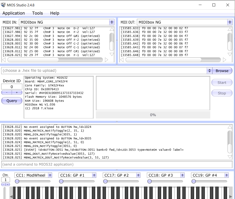
I fixed nearly everything, the only thing that is left are those stupid random messages that appear in lightspeed :((
They also appear if i only attach the RH-Lemec to the Ucore and dont load any app or NG file:
[22732.580] set debug on
[22734.666] Debug mode turned on
[22734.675] MBNG_DIN_NotifyToggle(129, 0)
[22734.675] No event assigned to BUTTON hw_id=129
[22734.675] MBNG_DIN_NotifyToggle(130, 0)
........ (counts to 256)
[22734.832] MBNG_DIN_NotifyToggle(256, 0)
[22734.832] No event assigned to BUTTON hw_id=256
[22734.844] MBNG_DIN_NotifyToggle(1, 1)
[22734.844] [EVENT] id=BUTTON:1 hw_id=BUTTON:1 bank=0 fwd_id=LED:1 type=NoteOn value=127 label=^std_btn
[22734.844] MBNG_DOUT_NotifyReceivedValue(1, 0)
[22734.844] MBNG_DIN_NotifyToggle(2, 1)
[22734.845] [EVENT] id=BUTTON:2 hw_id=BUTTON:2 bank=0 fwd_id=LED:2 type=NoteOn value=127 label=^std_btn
[22734.845] MBNG_DOUT_NotifyReceivedValue(2, 0)............................. and so on. It repeats in a loop. First it comes in slow bursts and then suddenly it starts to go wild
-
17 hours ago, latigid on said:
If there is a systematic error here, please provide all of the info possible, especially the voltage outputs of 595 registers, results of NG tests including manual control.
Random trigger behaviour can indicate issues with the DIN shift registers. Check that all resistor networks are the correct type and properly installed with the polarity mark aligned with that on the silkscreen. Check soldering once again, check and swap ribbon cables.
Did you reload _L.NGC and use the unmodified file?
Correct, IC1/3/5 are the 74HC165s.
Before IC is the J89 connector. The SI pin is pin five (middle pin closest to the notch).
Keep on trying and it should work someday :
I modified _R.NGC for the testing with only Lemec RH so when I connected all Pcbs (ucore + ja +lemec LH + rh) I used _L. NGC which was unmodified. Should I modifie _L. NGC instead for the lemec rh test?
Also, the resistor network next to IC1 seems to have troubles since I measure 8.3kOhm between first and second pin (shouldn't it be 10k?).
Another question. I found out that IC17 is not connected to VCC on Pin16 (no contuinit to the pin on the J89 connector). Is that on purpose?
Thanks in advance...
-
On 6/16/2019 at 7:08 PM, latigid on said:
Not sure.
Disconnect all PCBs, connect lemec_L directly to the Core J89 (without JA) and load seq_R.ngc. You can also connect lemec_R directly to the Core, but you need the following modifications:
################################################################################
# Left Panel
################################################################################

...


# 8x8 Button/LED matrix - we emulate "normal" LED/Button functions:
DOUT_MATRIX n=1  rows=8 inverted_sel=1 inverted_row=1  sr_dout_sel1=4  sr_dout_r1=5  led_emu_id_offset=1001
DIN_MATRIX  n=1  rows=8 inverted_sel=1 inverted_row=0  sr_dout_sel1=4  sr_din1=2     button_emu_id_offset=1001
(i.e. offset the DOUTs by three)
Hello, i tried most of the things you told me so I need to report :-). When connecting the LH Lemec directly to the uCore all switches and encoders work and I got no strange debug-messages. When connecting the RH Lemec directly to the uCore i have no response of the PCB. I modified the seq_R.ngc as shown above and when loading it i get a bit of debug output (see picture 1 please).
When connecting the whole Chain uCore - JA - Lemec LH - Lemec RH, i now get triggers and debug-messages all over the place and none of the encoders on both boards seem to work (hard to tell because of the many random messages). Also the LEDS on the JAboard dont work in this setup (without Lemec RH they work fine when buttons are pressed). I tried to reflow the ICs and checked for contuinity between the ICs. You explained that there should be contuinity from IC1 Pin 10 to IC2 Pin 9 and I got contutinity from IC1 Pin10 to IC3 Pin 9 -I refer to the labels on the PCB (which is also the case on Lemec LH) So I at least got contuinity but could you please explain me what comes before IC1 that could have the effect of making trouble for the whole PCB and chain respectively causing random trigger messages (see picture 2 please).
I'm very thankful for your help and since I'm pretty stuck now it always feels so nice to read your thoughts.
Greetings, Alex

-
38 minutes ago, CJ55 said:
@pat_00 It looks like the LED on switch 17 is dead. I had the same problem (strange) with the same effect! First it worked all perfectly well and after some testing the same LEDs as on your picture constantly lit.
Maybe the problem is the bending to fit into the switch and the colored LEDs are more sensible in this regard.
@pat_00@CJ55 I also have the same issue but when NG is loaded the LEDs light up just fine when the buttons are pressed (also the green one) - will anyway swap it out to make sure its not the fault of said LED
-
16 minutes ago, Dimduj said:
Mmmhhh cannot help further sorry :/
One last advice, Before soldering mathias switch take time to recover them with electrical tape or paint sides with a marker to avoid light bleed between them.
i was really annoying with light bleed between steps.
Caps are hard ( impossible ? ) to remove once placed and it took me lot of time to place tape to isolate light with caps installed.
Cheers
thanks, nice info - will do it when i figured out whats wrong at the moment :(
-
21 minutes ago, Dimduj said:
Hi all,
@knochenfabrik just my two cents: Did you check the last/first encoder pins are not touching the pins of the ribbon header .
You can check that looking at the side of your build?
Thanks for your input - i checked it but there seems to be no short anywhere - On the LEMEC RH PCB however i have only installed the header in the J89 slot and not the J89A because it is the last module in the chain (am I wrong there) so there isnt realy the possibility of such a short right now. So my chain right now is from JApcb J89-port to J89-port of LEMEC LH and from the J89A-port to J89 port of the LEMEC RH.
-
OK when the LH pcb is connected to the core J89 it works fine and everything is registered so I modified the SEQ_R and tried it with the RH pcb but there is nothing - will have to measure continuity later - the pcb just seems to do nothing right now :-/.
I also tried to set on/off pins individually how it is mentioned in this thread a bit earlier but it didnt realy do anything - maybe i also should try it again.
Thank you very much...


Troubleshooting midiphy SEQ v4+
in MIDIbox SEQ
Posted · Edited by knochenfabrik
@latigid on@Hawkeye Thanks for the input. My current situation is:
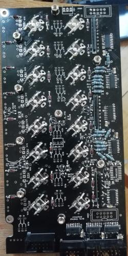
DOUT: Had the whole module working fine - suddenly from nowhere the 2nd LED began to blink randomly so i reflowed the whole PCB and now everything looks good and working as intended.
AOUT: After your first feedback I reflowed all the components you mentioned (IC4, 8RX, etc.) and to my surprise got channel 7 and 8 of the AOUT-module working fine. The other channels though didnt work as intended anymore and on J3 i measured pefect 5V on Pin 7,8. On the other pins i measure voltages from 3.6 (e.g. Pin 6) to 5.7 (e.g. Pin 1) and most channels of the DOUT didntt work as intended when using to control a VCO. So I thought to myself lets reflow all the other ICs and important Rs and Cs aswell. The result is that channel 7 and 8 (which I havent even touched this time) dont work anymore but channel 1-7works fine now.
I still owe you a better picture with voltage information - but now that everything is twisted again I have to measure again and create a new picture :D