CJ55
-
Posts
64 -
Joined
-
Last visited
-
Days Won
4
Recent Profile Visitors
3,576 profile views


CJ55's Achievements
MIDIbox Newbie (1/4)
5
Reputation
-
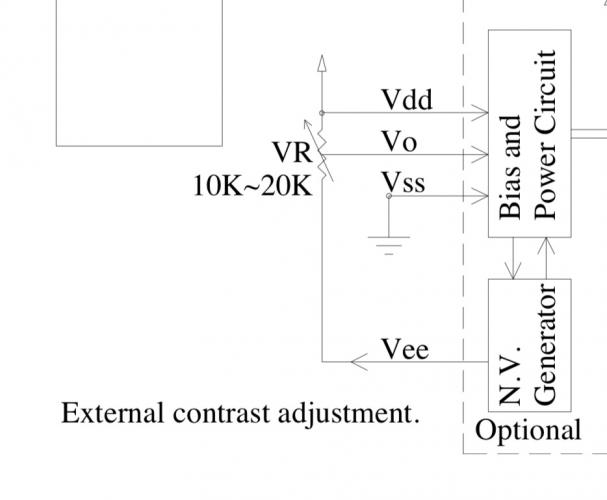
Pin15 (Vee) on the Midas display is a negative voltage OUTPUT! So do not connect this pin to your Midibox PCB. Instead connect it like in the circuit from the data sheet with a 10k-20k trimmer to Pin3 (Vo) and Pin2 (Vdd). In this case Pin3 also must not be connected to your Midibox PCB.
-
Which resistor network are you using exactly? The data sheet (from your link) shows 3 different versions: isolated (-102), bussed (-101) and dual terminator (-104). You need the bussed ones!
-
Definitely a scam web shop! All fictional prices and pictures stolen from Ebay! New iPad for 20€ instead of 40€! Ha, ha!
-
Here are some order numbers for IDC sockets from Reichelt: 10 pin: „PFL 10“ €0,11 16 pin: „PFL 16“ €0,19 24 pin: „3M 36266600“ €2,25 (only available from 3M, actually I like the cheaper PFL more) Shipping cost to France: €5,60
-
For Sale - kinda cheap too! MB6582 Panelkit (julianf) + Soldered CS PCB
CJ55 replied to technobreath's topic in Fleamarket
Ok, I agree to take the burden off your shoulder ;-) 99,- Euro seems to be fair! Could you please give me an estimate of the shipping cost to Germany? -
@pat_00 It looks like the LED on switch 17 is dead. I had the same problem (strange) with the same effect! First it worked all perfectly well and after some testing the same LEDs as on your picture constantly lit. Maybe the problem is the bending to fit into the switch and the colored LEDs are more sensible in this regard.
-
You just need to search for „1206“ and „560R“ and you will find a great selection at Mouser and Digikey available. Your first Reichelt link in your last post is also completely ok. Tolerance doesn‘t have to be better than 5%. Your second link to Reichelt is a resistor with 0.1% tolerance: Unnecessary expensive.
-
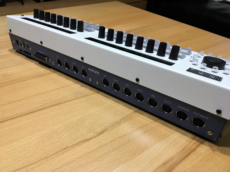
I have a question regarding the MIDI8 PCB. I thought the I4/PWR port would work as a MIDI IN also when using a DIN8 socket. Mine doesn‘t. So I disassembled the whole SEQ v4+ again to find the failure. There is no connection between pin4 of the DIN8 and the 220R to the optocoupler pin2. But there is a connection from the adjacent solderpad to the 220R to the optocoupler pin2. This pad would be used when using a DIN5 socket. Is this intentionally? Is this a failure on my board? Can I make this connection to the adjacent pad with a solderbridge? Or is there something I do not consider?
-
I had the same idea and wanted to use them. I have those connectors here but they do not work, because they will cover the mounting holes.
-
CJ55 changed their profile photo
-
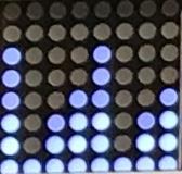
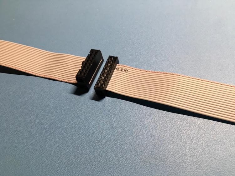
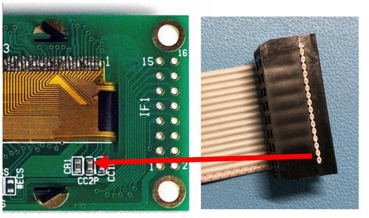
Here is the problem my OLED had: It took some time to find out the real problem. First I thought it was a problem with the OLED PCB, because slightly twisting it on the left side got the display fully working. And of course I testet the header, connector and cable twice before. So here is the problem: The unisolated end of the flat cable had contact with a capacitor on the OLED PCB. I prepared a picture showing it a bit clearer: I think this problem could happen to everyone and the solution is to use a bit of isolating tape between the connector and the PCB, especially the three components the arrow is pointing at in the picture above.

-
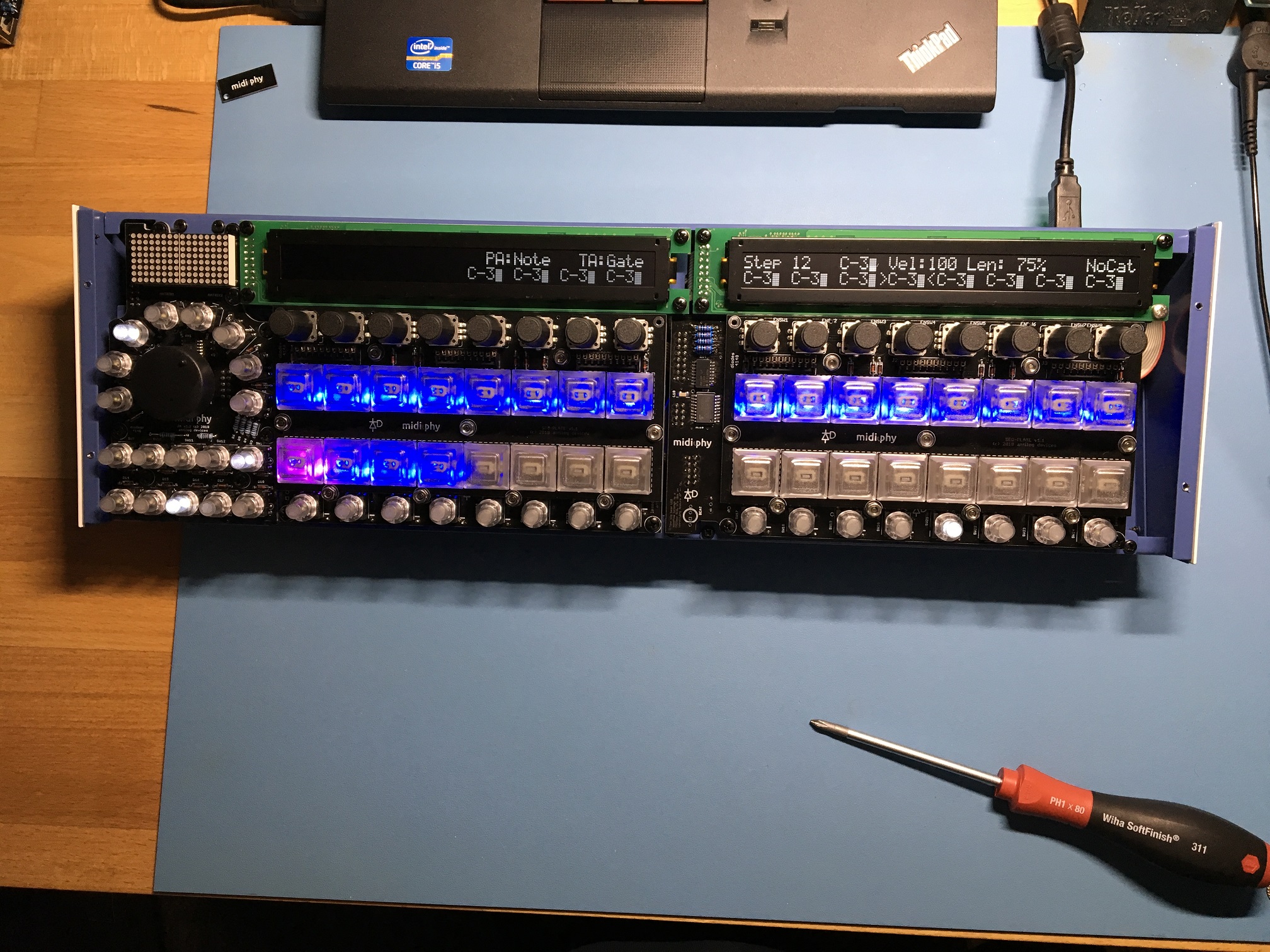
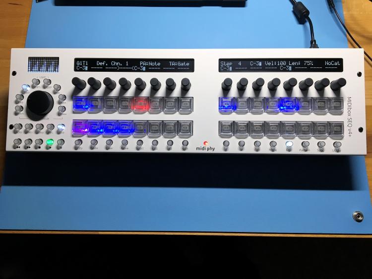
Happy New Year! Number 6 has a nice working OLED now! I will write something about how I fixed the problem in the Troubleshooting thread. Thank you Peter and Andy for your offer to replace the OLED!
-
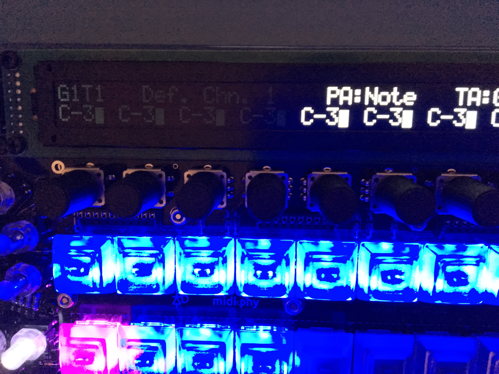
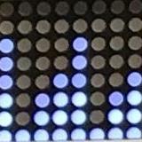
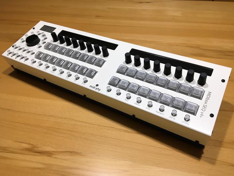
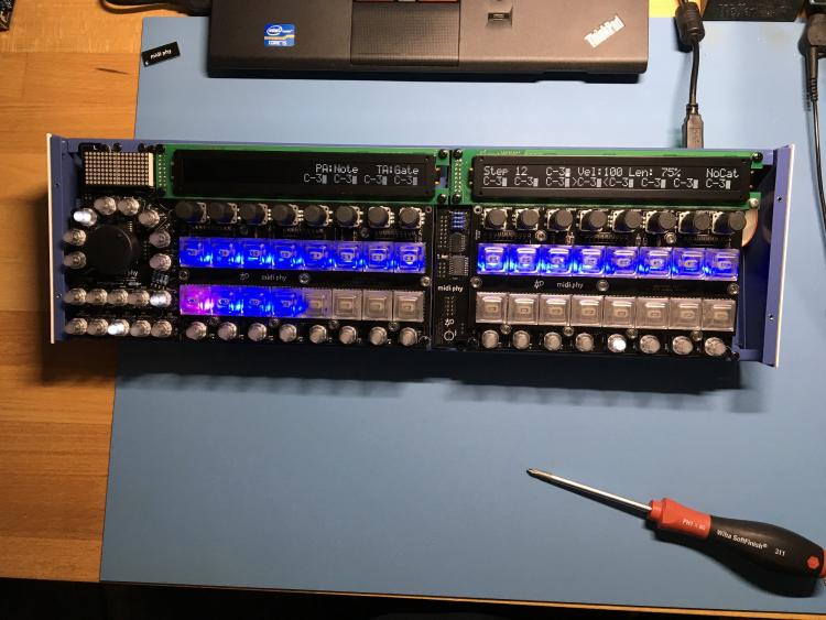
Almost Midiphy SEQ V4+ #6 Unfortunately I have a bad Display :-( On one OLED only the second half of it is lighting up. The first half is very, very dim. I ruled out the connector and the cable. It‘s a problem somewhere on the OLED PCB. When I bend it (twisting it) a little bit on the left side, the display shortly comes to full life. Can not find the problem. Most likely a cold solder joint on the 43 pin flex strip. I am building this SEQ for someone else and he is waiting yearningly for it. Bought it as part of a Midiphy kit. What shall I do?
-
Searching for someone to build me a MIDIbox SEQ in Germany
CJ55 replied to Super-Samurai's topic in MIDIbox SEQ
Hello Super-Samurai, if you want, I can build one for you. I‘m an experienced professional in Germany ;-) At least regarding electronics. I have a SEQ V4 and consider building a SEQ V4+ for myself. Just write me a message! -
Displays not initializing after working for a while
CJ55 replied to EvilEvilEvil's topic in MIDIbox SEQ
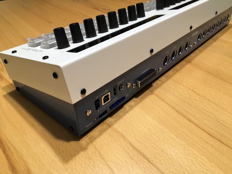
Maybe a voltage problem? I see in your pictures that you use the Mini-USB- port. The 5V of the Mini-USB port goes through a BAT60J diode to the board. It has a voltage drop of 0.28V... 0.58V depending on the current flowing through it. Do you have the same problem when using the Micro-USB port or an external power supply? -
Are you using the Micro-USB or the Mini-USB port for powering your SEQ? The 5V of the Micro-USB port is directly connected to PA9 which is then connected via the jumper J17 to the board. Exactly the same as you power your setup via J2. Should be no difference. The 5V of the Mini-USB port goes through a BAT60J diode to the board. It has a voltage drop of 0.28V... 0.58V depending on the current flowing through it.