totoRaymond
-
Posts
52 -
Joined
-
Last visited
-
Days Won
6
Content Type
Profiles
Forums
Blogs
Gallery
Everything posted by totoRaymond
-
No worrys, as I said, i think i will settle for this solution for now. I'd like to have a working build before end of the year and improve from there. If I remember well, you're problem with PWM was related to EMI leaking into the analog circuitry, not the actual physical noise of the fader. Am I right? You're right, the PIC used on MF_NG won't go higher in frequency, But if need be, i'm not afraid to port the code to a more capable micro... (as long as i have a working controller, i have all the time in the world to make it better... ) I never looked inside a D-command, but if i get a chance, i'll check the Ic's used (might even look inside an Avid S6, who knows, those faders are great). I'm going to start looking into some other controllers too. Thanks! Thomas
-
You need to download an old version of MPLAB to use a pickit 2. A quick search in google tells me MPLAB IDE v8.92 is the latest version with pickit2 support. all older versions of mplab are available on microchip webpage: https://www.microchip.com/development-tools/pic-and-dspic-downloads-archive Or you can buy pickit3 or 4 and use MPLAB X Cheers, Thomas
-
Hi Zam, After reading ths whole topic again last week-end, I tried to lower the voltage. With Vm down to about 4V, i was able to get rid of most of the mechanical noise, but now the faders are a bit sluggish (actually, there's only one fader wired to the board right now). The PWM might be the problem, I know you went another route for your analog automation system (I followed the story since the beginning on gdyi). Do you think we could get rid of that noise using a higher PWM frequency? Or is it necessary to drive faders with DACs instead? There must be a way to drive faders in silence, I work all day on digidesign D-Command, they use the same ALPS K-faders I have and they're very quiet (and fast). I think i could live with slow faders for a time, but I might try to move to another solution once my controller is finally assembled. Cheers, Thomas
-
There is, but not in the more usual form of an analog signal. It acts as an encoder, sending pulses when you move the fader. Yes, that's how these faders are used A DIN is a module connected to a core module. It's used to interact with pushbuttons / switches and encoders. Look at ucapps.de, evrything is explained there. Yes I'm afraid it would not be an easy setup. But... you would learn a LOT of things in the way !!!! To me at least, that's where the fun is. I'm currently building my own DAW controller, and i know more things than before i started. And i intend to keep learning and improve. So don't let anything stand in your way if you really want to build it. And maybe you could contribute to the community this way. This way of driving faders looks very nice, without the resistive element, faders won't tear like standard ones, feeling might be better, and less noisy. I'm tempted to try and mod a fader to use this tech (but not today). Cheers, Thomas
-
According to datasheet, it's rather a 512 steps/turn encoder. ref is IE2 512 250 (i read wrong in the previous post). Assuming the datasheet didn't change in more than 20 years (which is possible with these kind of product). Then you might be able to drive them with MidiBox NG, but you would need to modify the code i guess. My knowledge stops at this point though, I'm not comfortable enough with C / ASM... The manufacturer of these motors also provides some control boards for them. Might be worth a look, but most of them use CAN or RS232 buses... so no direct compatibility with MidiBox. Cheers, Thomas
-
Well, that's also a possibility. Now that you mention it, the second ref on the motor might refer to this https://www.faulhaber.com/fileadmin/Import/Media/FR_IE2-1024_DFF.pdf Or rather an discontinued version of it? IE2 512 256 would then mean 512 or 256 impulse per turn. In this case, you can't use MB_MF_NG to control them. Cheers, Thomas
-
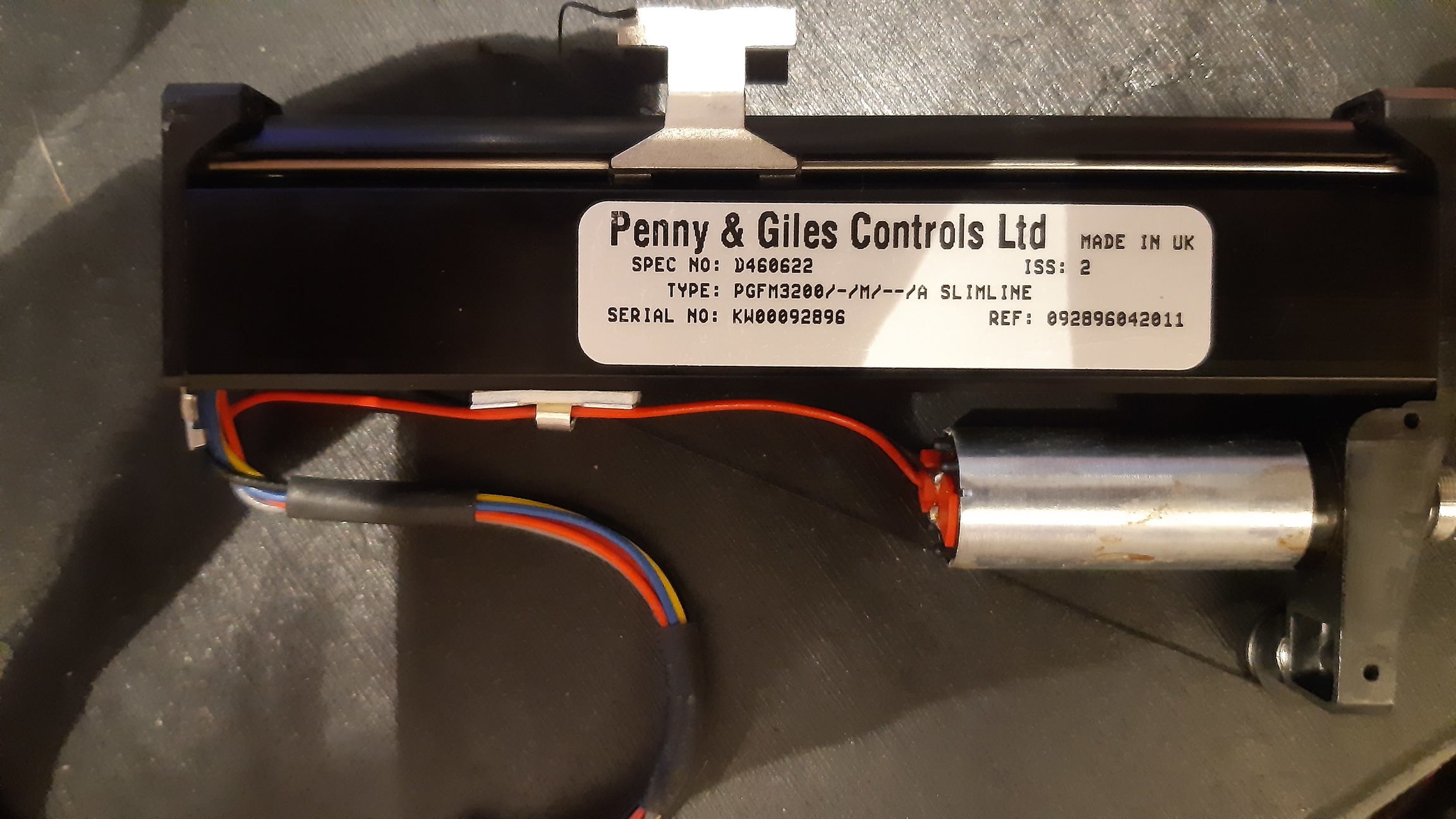
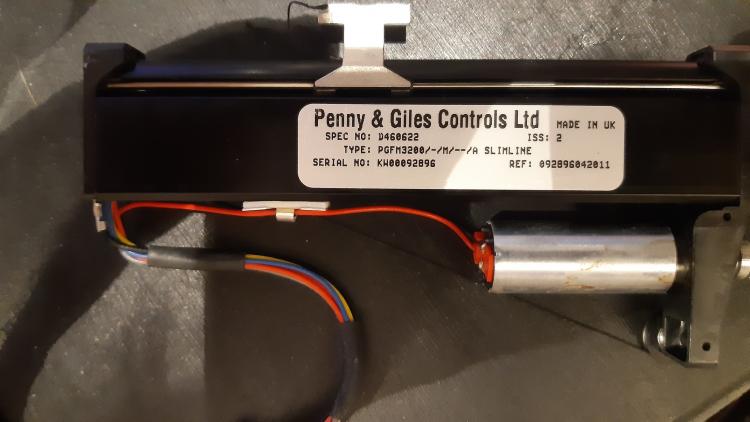
Hi, This is all good information, we're closing in... So 1 and 2 should be the DC motor as I expected. Now the four others must be 100%V, 0%V, Wiper, and Touch sense. In that order IF P&G kept the same when changing design. (which they seem to be doing) The other measurement don't make much sense though, maybe an error when measuring? 800k is really high for any kind of fader. measure between each pin and the lever. One should be a short and the others should be open. That would indentifiy the Touch Sense pin. This should left you with the potentiometer pins. So measure with different fader positions and report us with what you found. We're expecting a fixed 10k between two pins and a variation between 0-10k between 3rd pin and both others (one increasing while the other decrease). Tell us what you found! Cheers, Thomas
-
Yes they're probably older versions, but as I said, i have another old version of P&G motor fader here and the one I have here are already called PGFM3200 (not PGF3200). And they comply to the last datasheet even if they have a different mecanical arrangment: Waiting for more info on that... Cheers, Thomas
-
Hi, these look weird. P&G motorfaders should be PGFM3200. And the motor should be top or bottom. Maybe a custom job for a manufacturer? Do you have photos of the whole assembly? Where do they come from? Which console? It could be an older model, but it seems unlikely to me. I have a quite old P&G fader here, and it's already named PGFM3200 and has the same color coding than the more recent ones. Those motors look like 6v DC motors so you should be able to drive them with MB_MF_NG module https://www.faulhaber.com/fr/produits/series/2224sr/ Can you measure DC Resistance between different wires? With a ribbon cable like this one, red identifies pin 1. Cheers, Thomas
-
Hi, I'm not sure i undesrtood your question well but it seems to me that you need to use the bank function. for example: EVENT_ENC id= 1 hw_id= 1 bank= 1 type= CC chn= 1 cc= 0 range= 0:127 fwd_to_lcd=1 lcd_pos=1:1:1 label= "%3d" EVENT_ENC id= 2 hw_id= 1 bank= 2 type= CC chn= 1 cc= 1 range= 0:127 fwd_to_lcd=1 lcd_pos=1:1:1 label= "%3d" EVENT_ENC id= 3 hw_id= 1 bank= 3 type= CC chn= 1 cc= 2 range= 0:127 fwd_to_lcd=1 lcd_pos=1:1:1 label= "%3d" EVENT_BUTTON id= 4 fwd_id= LED:4 type= Meta meta= SetBankOfHwId:1 range=1:1 button_mode= OnOnly # "Bank 1" EVENT_BUTTON id= 5 fwd_id= LED:5 type= Meta meta= SetBankOfHwId:1 range=2:2 button_mode= OnOnly # "Bank 2" EVENT_BUTTON id= 6 fwd_id= LED:6 type= Meta meta= SetBankOfHwId:1 range=3:3 button_mode= OnOnly # "Bank 3" In this example, when you press a button, it activates the corresponding EVENT_ENC and deactivates the others. Is it what you're looking for? Cheers, Thomas
-
Hi! I'm having troubles setting up MF_NG. Everything seems to work fine, i was able to get faders moving and all, but there's a big rattle noise when faders are moving slowly (ie using the MIOS studio tool to make them move slowly, or following the daw automation). this rattling noise disapear when faders are moving fast. I tried to play with the different parameters, but i couldn't find a way to make that noise disapear. Currently i'm using ALPS K faders. but i got the same issue with an old P&G i had lying around. I tried 8 faders and had the issue with all of them. I'm pretty sure i'm doing something wrong here, but i can't figure out what... Thank for your help! Thomas
-
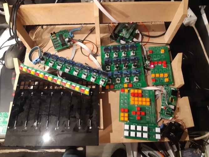
Hi Everyone! It's been a while since my last update, but the project keeps going on. Although a bit slowly since the family got a new member. I now have almost every pcbs tested and working as intended! I just need to buy a few more switches a make a case for all that stuff! I'm still having trouble with motorfaders though... they work but make a big rattling noise when moving slowly... Cheers! Thomas
-
No genius, thank you everything is explained in the documentation on ucapps.de even if I think some parts are not very clear. But now that you have a starting point you can experiment with all the possibilities that midibox NG can give you. Take the time to read the User Manual several times. And look at the examples on this page: https://github.com/midibox/mios32/tree/master/apps/controllers/midibox_ng_v1/cfg/tests Have fun! Thomas
-
Hi, I'm no expert but I think your definition is wrong. You need a EVENT_* in order to send MIDI events. Try this: #definition of buttons matrix DIN_MATRIX n=1 rows=8 sr_dout_sel1=1 sr_din1=1 button_emu_id_offset=1001 #defines which SR to use and the hw_id of switches from 1001 to 1064 #definition for EVENT_BUTTON starting from id 1001 EVENT_BUTTON id= 1001 type= CC chn= 1 cc= 0 range= 0:127 button_mode=OnOff #this sends a MIDI CC on address 0 on channel 1 when first button of DIN_MATRIX is pressed
-
Hi, as i was writing this post, things finally got to work! I'll still put my troubleshooting here for future reference, with corrections in red. Please anyone, correct me if i'm wrong I've been playing with my screens on a breadboard. I wired a 74HC595 to adress screens 9 to 16 as in this schematic: I assumed QA has to be wired to screen 9 CS pin, QB to screen 10 etc. !!! as in Dout modules, outputs of 74HC595 seems to be "reversed" ie: QH is screen 9 and QA is screen 16. So far, it's not been working as intended. Both screens display the same text as if they are enabled all the time. I put some leds in parallel with CS pins, to see if they blinked and they did NOT blink when changing display. (as it should in normal operation). So i wired my analog scope to monitor SCLK, RCLK and SER signals, and figured that there was no SCLK on pin 4 of J10B. Finally i found a "solution" (more of a workaround really) by complete luck. I just changed the number of oled declared in the bootloader from 16 to 64 and TADA! now i can monitor an SCLK signal and screesn are working as intended. I tried to go back to 16 lcd , and it doesn't work anymore. Tried 32 screens... it works! 15 screens ? doesn't work... 17 screens? it works. It seems to me there's a bug with J10B port not initializing correctly when the number of oled screens declared is <17. Is it a known bug? Maybe someone else can check if they have the same behavior? I know very little about programming, but i would be happy to help solve this issue. Unfortunately, I only own an analog scope, so monitoring those signals, is not very easy. (I can only see flashes of signals happening). Cheers, Thomas
-
Hi! i'm interested in the 25 alps motorfaders and the joystick. Are the faders new or used? what is the joystick brand / datasheet? Thank you very much, Toto
-
Hi Andy, Thank you very much, for the moment, my aim is to roll my own pcbs, so i can keep things tidy in a quite small enclosure. But first, i'll try to breadboard something in the next few days. (unfortunately a miswiring seems to have killed my STM32F4-DISCO right now) Cheers, Thomas
-
Hi everyone! I finally received some ssd1306 oled screens last weeks and started to play with it. So far, eveything is fine, i've been able to adress up to 8 screens without problems. But for my project i intend to use 38 oled screens, so i would need a string of shift registers for CS pin. On this page: http://www.ucapps.de/midibox_ng_manual_lcd.html it says that you need to connect those shift register to J28. But... on the STM332F4 core module, i can't find J28. I guess the info didn't get updated from LPC17 core. So which connector should i use for these shift register? I was thinking about J19 or J16? Thank you very much for your help. Thomas
-
Hi! I made the same mistake recently. If it helps, i found some on aliexpress which seems compatible with MidiBox_NG: https://fr.aliexpress.com/item/32233300972.html?spm=a2g0w.12010612.8148356.5.58bf27a8d5IkVL I ordered a pair as samples 2 days ago. I don't expect them soon but i'll keep you updated when they arrive. Thomas
-
Ok, I think I found a solution to my problem. I used the meta=SetBankOfHwId:xxx parameter instead of meta=SetBank But it didn't work at first because for my test i was using switches with ids in range of 1001 to 1064 (Connected to a DIN_MATRIX with button_emu_id_offset=1001 parameter) And hw_id is limited to 1:255 range... Right now it seems to work as intended, but i need to do some more testings. Cheers, Thomas
-
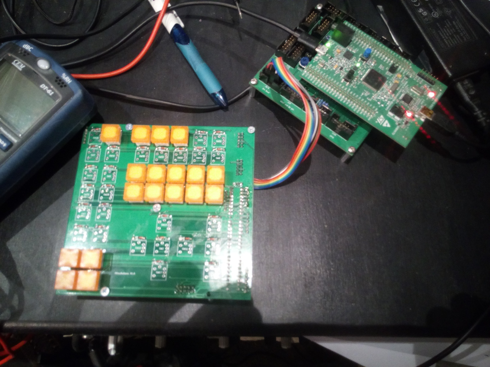
Hi everyone! it's been a while but i made some progress recently! I've received my first PCB along with some switches, and it works quite well (see below) More switches will be coming in the near future, but for financial reasons, i only ordered one color. I also ordered a few samples Oled screens from aliexpress. Unfortunately the first ones were I2C only, so i didn't manage to use them. ordered some new with SPI capability, but i don't expect them before christmas. Near future will be to assemble and try a MF_NG module and make a PCB for the second section of my controller (monitoring). But right now, i've been having troubles setting up banks. Any help would be appreciated. I'm trying to configure independant banks of encoders/switches. for example, Encoders 1 to 12 would be assigned to banks 1 to 8 Encoders 13 and 14 would be assigned to banks 9 to 12 I made a test and it kind of works, but if i select bank 9-12, encoders 1 to 12 wond send anything because, they aren't defined in this bank. And accordingly, i bank 1-8 is selected, encoders 13 and 14 won't send anything either I hope I made myself clear, it's quite difficult to express this kind of thing in a foreign language... Is it possible in the first place? Attached is a .ngc of my trials with switches instead of encoders. Thanks for your help, Thomas TestBanks.ngc

-
Hi! and sorry for double post... I have a question : Is it possible to get use the same DOUT Matrix for LED rings AND general purpose LEDs (like switch status)? Say i have an 8*16 Matrix and only want 11 LEDs for my rings, I could make use of those 5 left columns... After half a day searching it seems impossible, but i can't be sure... If not possible, then i might change my plan a little bit. Thanks! Thomas
-
Yeah, that's what i thought. But anyway, moving faders will probably be the last step of my build. First i'd like to get Switches, encoders and LEDs working. Thanks again! Thomas
-
Oh allriight i'll look deeper into it then. thanks for the tip! DAW implementation is not really an issue, they have what they called "generic remote" which gives you the ability to control most of Nuendo functions with any CC, SysEx or any MIDI event. Including "selected channel" parameters. Right now, i'm using this function with TouchOSC, but an iPad is not as good as a dedicated encoder / switch / joystick. Mackie Control protocol at least gives you track name feedback, and I could derive other information from incoming MIDI events i guess. As for buying, an off-the-shelf controller and add missing functions, i thought about it for sure, but it wouldn't be as ergonomic, which is a big concern to me. Plus, if i make my own solution, i would be able to scale it to my future needs, repair it, make it evolve with time. Which is not really possible with off-the-shelf solutions. Next step will be to make the channel encoders boards, with channel switches daughter board. 8 switchable encoders plus 4*8 switches = 56 Switches. 8*11 LED Rings plus 4*8 Buttons LEDs = 120 LEDs I figured i need 1 8*8 buttons matrix and 1 8*16 LED matrix. Is that correct? (maybe to 8*8 LED Matrices is better?) Thanks everyone for your help! Cheers, Thomas
-
Hi! I'm aware of Zam's Project, but as I understand it, it's more of a way to automate existing analog desk. I just need to control a DAW with MIDI events, not planning to get any analog signal involved. But i want more than faders. In fact, being able to access selected channel EQ / Dyn / surround Pan is the most important thing to me. Or else, i would just buy of the shelf Controller like Qcon / MCU / Behringer... But none of them offers me the ergonomics i want. Something very close to Avid Dcommand actually. Cheers, Thomas