

TK.
-
Posts
15,247 -
Joined
Content Type
Profiles
Forums
Blogs
Gallery
Posts posted by TK.
-
-
This is not the right way to update patch values.
Which synth are you using? Maybe there is a way to request a patch dump, and to pick up the values from this dump.
Best Regards, Thorsten.
-
Short update: the ESP32 based MBHP_MF_NG can now communicate with BLEMIDI over Bluetooth, Apple MIDI over WIFI, and traditional MIDI via UART
-> https://github.com/midibox/esp32-idf-mfdrv
Still some work to do, but I think that this is a pretty good basis for other MIDIbox projects - special focus was on reliable SysEx transfers and routing between different MIDI interfaces.
This major challenge is solved! :-)Best Regards, Thorsten.
-
(I've to think about your proposal about "bulk operations" on the active flags (and maybe others...)
To the problem: the reason, why the event doesn't update the LCD is because of the "0xf0" at the end of the SysEx strings, e.g.:
EVENT_ENC id=1 hw_id=1 label="@(1:1:1)Prm1 @(1:1:2)%03d" range=0:127 fwd_to_lcd=1 type=SysEx stream="0xf0 0x41 0x10 0x00 0x10 0x12 ^chk_start 0x1f 0x00 0x20 0x55 ^val ^chk_roland 0xf0"Just write 0xf7 instead, and the LCD will be refreshed, because this is what your synth will send.
It could be, that the same typo already caused other side effects, also on your synth.
Concerning the encoder value problem: check again with the updated definition, if it still happens I need a concrete configuration to test it at my side.
Best Regards, Thorsten.
-
Found it! :-)
This was an "unintended intended overwrite" of the value whenever F0 is received - stupid! -> https://github.com/midibox/mios32/commit/3982027d66f473b191d55898788872232dcf7cd2
Your input is really helpful to nail down such scenarios, thank you for this! :-)Updated version: http://www.ucapps.de/mios32/midibox_ng_v1_037_pre9.zip
Best Regards, Thorsten.
-
This is definitely not the intended behaviour!
I started to debug this at my side - the received values will be taken over as expected, but somehow they got lost (set to 0) *before* they are print out by the LCD.
Need more time to debug this...
Best Regards, Thorsten.
-
Glad you like it :)
New release location is here: https://github.com/midibox/mios8/tree/master/apps/synthesizers/midibox_sid_v2/presets
Best Regards, Thorsten.
-
I think that a ESP32 could handle the BLM16x16+X code internally, no need for a second core :)
Best Regards, Thorsten.
-
While waiting for the PCB I worked on the "Apple MIDI" protocol which allows to transfer MIDI messages over WIFI (and Ethernet - known from this project:
As a second project I consider to create a universal "MIDI bridge" device for MIDIbox projects which supports UART, Bluetooth, WIFI and SPI, maybe also CAN.
So, it can be connected via SPI port J28 to a MBHP_CORE_STM32/F4/LPC17 instead of the MBHP_ETH module, or alternatively via UART (e.g. also to PIC based projects) giving us wireless connections :)
The latency is not so nice - expect ca. 5 mS + some jitter - it won't be really suitable for sending MIDI Notes, but it will be very nice for MIDI controllers.
Another topic which needs to be explored: if the antenna is strong enough to send/receive in a metal case, like MIDIphy MBSEQ V4+
Best Regards, Thorsten.
-
It won't work with newer MIDI devices which supply 3.3V on the MIDI Out port (some devices from "MIDI Solutions" are affected by the same problem...)
Best Regards, Thorsten.
-
Happy new year! :-)
Best Regards, Thorsten.
-
An interesting case - it seems that I never tested incoming SysEx streams while parsing ^chk_start - this was causing the endless loop and it's fixed now:
-> http://www.ucapps.de/mios32/midibox_ng_v1_037_pre8.zip
Note that with this change the EVENT_ENCs will update their value according to the specified SysEx stream.
Which means, that the EVENT_RECEIVER is not required anymore.And the way it's currently used it causes a problem with EVENT_ENC id=2 (which picks up the checksum via syxdump_pos=1:1)
So, just remove EVENT_RECEIVER and maybe also the syxdump_pos arguments - they are intended to pick up values from "patch dumps"
Best Regards, Thorsten.
-
The NRPN number issue is fixed now:
http://www.ucapps.de/mios32/midibox_ng_v1_037_pre7.zipHowever, I can't reproduce the screen freeze - there might be additional events which are causing this?
Could you please minimize the example?Best Regards, Thorsten.
-
There are some problems with this configuration:
-
syxdump_pos=1:x --- x starts counting from 0, not 1
Means: with syxdump_pos=1:0 you should get the expected "25" of "f0 25 f7" - the value will be put into the first ENC event with ID 1, the second one with the same ID won't get the value
- I think that you defined two events with the same ID since you wanted to print out something at a second line. This can also be done with a single event, just use the "@(lcd:x:y)" keyword
- it makes sense to use "%3d" instead of "%d" to ensure that the decimal value (overwrites) 3 characters
- by adding fwd_to_lcd=1 the received SysEx value will be displayed immediately
So, just replace the 4 EVENT_ENC lines by following 2 lines:
EVENT_ENC id=1   hw_id=1  fwd_to_lcd=1  lcd_pos=1:1:1   label="Prm1 @(1:1:2)%3d  "  range=0:127  syxdump_pos=1:0
EVENT_ENC id=2   hw_id=2  fwd_to_lcd=1  lcd_pos=1:6:1   label="Prm2 @(1:6:2)%3d  "  range=0:127  syxdump_pos=1:1
Best Regards, Thorsten.
-
syxdump_pos=1:x --- x starts counting from 0, not 1
-
I added some code which should allow proper calibration of Hz/V - could you please check at your side?
-> http://www.ucapps.de/mios32/midibox_seq_v4_096_pre11.zip
Note also: by pushing the GP7 button in CV page we can now switch to bipolar voltage display, which is a bit more convenient :)
Best Regards, Thorsten.
-
Let me check first if something can be done at the SW side (tomorrow...)
Best Regards, Thorsten.
-
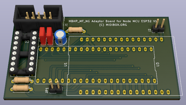
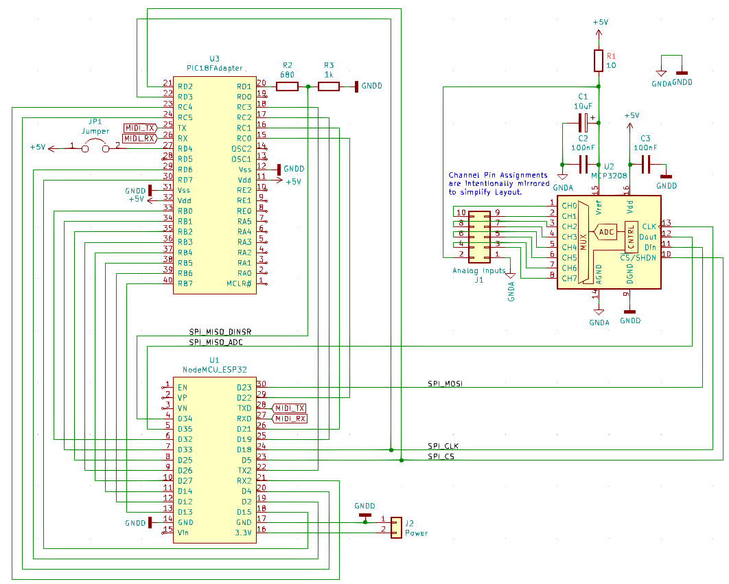
My first KiCAD project - I don't miss xcircuit and Eagle & I'm happy that other people can now edit the files with state-of-the-art open source SW as well :-)

Best Regards, Thorsten.
P.S.: ordered at OSHpark - let's see if the circuit works like intended next year :)
-
-
The EVENTs which are controlled via NGR script shouldn't be assigned to a bank, otherwise concurrent changes on the "active" flag will happen.
Therefore just write:
# select tone 1-2 and trigger NGR script
MAP1 1 2
EVENT_BUTTON id=35  hw_id=35 range=map1 button_mode=Toggle type=meta meta=RunSection:1

# select bank and trigger NGR script
EVENT_BUTTON id=36 hw_id=36 type=Meta meta=CycleBank meta=RunSection:1 button_mode=OnOnly

# dummies to define bank1/2
# can be removed if banks are defined for other events (not controlled from NGR script)
EVENT_BUTTON id=3001 bank=1
EVENT_BUTTON id=3002 bank=2


### First page
EVENT_ENC id=1   hw_id=1  lcd_pos=1:1:1   label="1_1%B "
EVENT_ENC id=2   hw_id=1  lcd_pos=1:1:1   label="1_2%B "
EVENT_ENC id=3   hw_id=2  lcd_pos=1:6:1   label="2_1%B "
EVENT_ENC id=4   hw_id=2  lcd_pos=1:6:1   label="2_2%B "

### Second page
EVENT_ENC id=5   hw_id=1  lcd_pos=1:1:1   label="9_1%B "
EVENT_ENC id=6   hw_id=1  lcd_pos=1:1:1   label="9_2%B "
EVENT_ENC id=7   hw_id=2  lcd_pos=1:6:1   label="A_1%B "
EVENT_ENC id=8   hw_id=2  lcd_pos=1:6:1   label="A_2%B "
And in the NGR script I noticed some wrong "endif" statements.
"elsif" will only work for the previous "if" condition if you don't terminate it with "endif":### First page of parameters if ^bank == 1 LOG "First Bank" ### tone 1 if (id)BUTTON:35 == 1 set_active (id)ENC:1 1 set_active (id)ENC:2 0 set_active (id)ENC:3 1 set_active (id)ENC:4 0 set_active (id)ENC:5 0 set_active (id)ENC:6 0 set_active (id)ENC:7 0 set_active (id)ENC:8 0 ### tone 2 elsif (id)BUTTON:35 == 2 set_active (id)ENC:1 0 set_active (id)ENC:2 1 set_active (id)ENC:3 0 set_active (id)ENC:4 1 set_active (id)ENC:5 0 set_active (id)ENC:6 0 set_active (id)ENC:7 0 set_active (id)ENC:8 0 endif ### Second page of parameters elsif ^bank == 2 LOG "Second Bank" ### tone 1 if (id)BUTTON:35 == 1 set_active (id)ENC:1 0 set_active (id)ENC:2 0 set_active (id)ENC:3 0 set_active (id)ENC:4 0 set_active (id)ENC:5 1 set_active (id)ENC:6 0 set_active (id)ENC:7 1 set_active (id)ENC:8 0 ### tone 2 elsif (id)BUTTON:35 == 2 set_active (id)ENC:1 0 set_active (id)ENC:2 0 set_active (id)ENC:3 0 set_active (id)ENC:4 0 set_active (id)ENC:5 0 set_active (id)ENC:6 1 set_active (id)ENC:7 0 set_active (id)ENC:8 1 endif endif exit
With these changes it works at my side :)
Best Regards, Thorsten.
-
Hi,
if_equal will match the EVENT value, not the bank, therefore this function won't help for the intended purpose.
For complex banking schemes I introduced the NGR command "set_active", where the script can activate/deactivate EVENTs based on your own rules.
E.g. following example shows how to activate/deactivate based on the variable ^bank:
- https://github.com/midibox/mios32/blob/master/apps/controllers/midibox_ng_v1/cfg/tests/multibnk.ngc
- https://github.com/midibox/mios32/blob/master/apps/controllers/midibox_ng_v1/cfg/tests/multibnk.ngrIn your case, you would add BUTTON:33 with an additional "if" condition to activate/deactivate (id)ENC:1 and (id)ENC:2
It will result into a very long NGR script - but it should work (and should be fast enough)
Best Regards, Thorsten.
-
I can't recommend this solution; it only transfers via a serial protocol, which then has to be converted by a computer into MIDI messages - this is error prone.
Today we would prefer the BLE MIDI protocol, which is natively supported by many operating systems, and considers special MIDI features such as continuous SysEx streams.
And this is possible with a simple ESP32 controller, which is available for the same (or less) price - and on top of this WiFi should be possible as well.Best Regards, Thorsten.
-
Hi Analog_mo,
I don't have enough expertise in this area to assess your circuit proposal, but can give you an alternative advice:
There is a new C64 PSU available which seems to be safer:
I use it with my MBSID meanwhile because of the same worries that you have...
Best Regards, Thorsten.
-
Cool, I like CME :)
Best Regards, Thorsten.
-
And never forget: from a loopback track it's possible to control sequencer parameters of another track, here the corresponding parameter numbers: https://github.com/midibox/mios32/blob/master/apps/sequencers/midibox_seq_v4/doc/mbseqv4_cc_implementation.txt
And while I was writing this, I remembered that I wanted to make this function also available from a parameter layer.
Here it is: http://www.ucapps.de/mios32/midibox_seq_v4_096_pre10.zip
Quoteo New parameter layer "Ctrl" allows to change track parameters as documented in
the doc/mbseqv4_cc_implementation.txt table (previously this was only possible
from a dedicated loopback track)
E.g. in the Event configuration page, I assigned Par. Layer E to Ctrl: Echo Rep. and Layer F to Ctrl: EchoFB.V - and it works: with each step a new value can be set, or previous setting will be kept if "---" is selected (turn encoder full-right)
Best Regards, Thorsten.
-
Reproducibility proven - great! :)
Best Regards, Thorsten.

MBCV2 Levels
in Testing/Troubleshooting
Posted
Hi David,
a feature that I recently implemented for MBSEQ would help here - and actually I already planned to integrate it into MBCV and MBNG as well: the calibration points.
See apps/sequencers/midibox_seq_v4, search for AOUT_NUM_CALI_POINTS
Would you like to add this by yourself, or should I do this?
Best Regards, Thorsten.