

Duggle
-
Posts
992 -
Joined
-
Last visited
-
Days Won
5
Content Type
Profiles
Forums
Blogs
Gallery
Everything posted by Duggle
-
From the album: Duggle
-
From the album: Duggle
-

From the album: Duggle
-
From the album: Duggle
-
From the album: Duggle
-
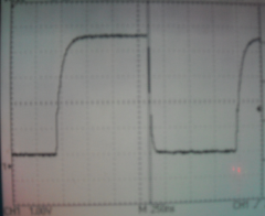
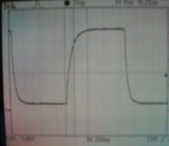
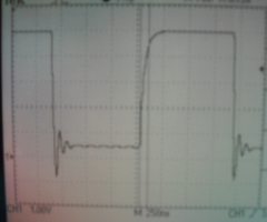
Abstract Discussion of the problems limiting the length of SRIO chains. Some causes of signal integrity problems in transmission lines are mentioned. A Working solution is presented. Introduction The problems limiting the length (physical length and the number of chips connected) of DOUT shift registers has been canvassed during the development of my Midi Keyboard LED Display (MKLD) project. MKLD Itself is the subject of an upcoming blog article. Suffice it to say for now that the design uses 24x 74HC595 chips to drive a display that covers a 4 octave keyboard. I intend to drive 2 keyboards this way adding up to 48 chips. A limit of 16 shift register chips in SRIO chains has been arrived at empirically. This has been based on the number of chips (contained in DOUT modules for instance) that can be reliably successfully controlled. MIOS32 can address an arbitrary number however, but problems can and will arise after a certain number of shift registers are attached. Rudimentary signal integrity for transmission lines When the clock rate of data is high and the physical length of signal traces in long relative to it, the wave shape of signals can change to the point where the circuit no no longer functions reliably unless special steps are taken in the design to prevent this. In an absolute nutshell: voltage wave reflections due to characteristic impedance changes (particularly at the end of the line) interact with the distributed LRC impedances to produce ringing. "The crude rule of thumb are that a conductor is electrically long when it exceeds one-seventh of the shortest wavelength of concern, or when the time that the leading edge of a signal takes to travel from the source to the furthest receiver exceeds half of its rise or fall times. " Reference The article quoted above provides the estimate for a circuit board of 6.7ns/m for speed of signal. So in the case I have encountered with MKLD length of say 4m, signal travel time is around 30ns. The "crude rule of thumb" states that the rise time of my clock signal should not be less than 60ns. In practise with the MKLD circuit Simply connecting the DOUT port of J8 of the MBHP Core STM32 to the MKLD string of 30 shift registers has worked. But the seeds of a problem are there to see: SCLK signal measured at the end of the chain The falling edge (driven low by the open drain output of the STM32) is rather fast (<~20ns). There is distinct ringing occurring. Interestingly, the rising edge (driven high by the 220 ohm pullup) is slower (~100ns). No sign of ringing. The input capacitance of the inputs of 74HC595 is 3.5pF per input. With 30 shift registers, the SCLK line has a total capacitance of (3.5*30)=105pF The RC time constant (time for a rise/fall of 66% of max/min) is (220*105)ps= 23.1ns. This suggests that the parasitic capacitance (that caused by the ribbon wire and pcb tracks, totalling close to 2m in length) may be more significant. SCLK signal measured at the end of the chain This is with a series 220 ohm resistor at the source. The falling edge no longer has any trace of ringing. SCLK signal measured at the end of the chain Using 100 Ohm resistor. Better wave shape. The cursors measure ~20ns fall time. The actual test setup is probably only around 1.5m in signal path length. Conclusion It is useful to note that the "solution" here is not impedance matching but rather making use of parasitic capacitance in conjunction with an applied series resistor to slow down the edges of the SCLK signal to the point where transmission line effects are not observed. This is only possible due to the relatively slow clock used by MIOS32. There is no performance hit as the transfer is using DMA. With an update period of 1ms, there is a theoretical limit of nearly 1000 bits of SRIO that may be transferred. Other points to mention are that the RCLK signal has timing such that it has plenty of time to settle where there are no changes in either DIN In or SCLK. DIN is also physically shorter and is resynchronised with each chip therefore less likely to need a series resistor. The "Working solution" may or may not work for MIOS8 systems where the bit-banged SRIO is considerably faster clocked. I would suggest smaller series R. And finally, I'd love to hear from any signal integrity experts on any false statements or assumptions or analysis that is unreasonably flawed. Comments welcome! Pictures and text © Duggle 2010
-
From the album: Duggle
-
Getting Open OCD working with Amontec JTAG Key (WinXP)
Duggle commented on Duggle's blog entry in Duggle's Blog
Just attempted to install 0.4.0 on my laptop and found that there was failure at step 4). Uninstalling then installing 0.2.0 has it working. -
Ive used KICAD and it is very good. I didn't know about eagle compatibility. Another contender!
-
How to kill an STM32 in one easy lesson
Duggle replied to philetaylor's topic in Testing/Troubleshooting
Phil, Its actually really easy (the chip is shot, so just cut it out) here's how to do it: 1) Take a scalpel or box cutter or whatever its called in your locale. 2) Gently run the blade across the pins close to, or against the chip package in such a way as to shear the pins off at the body. Use just enough force to shear the pins without cutting into the PCB. An easy gentle motion will cut the pins along one side of the IC in one stroke. If not, go at a speed that is comfortable. 3) Remove the chip package. With a soldering iron and a pair of tweezers, pick the leads of the PCB. 4) Take some wick and remove solder and any pin fragments from the footprint. 5) Solder in the new chip! 6) Don't reverse J23 ;-) -
I guess having RS numbers included in the BOM output is a clue that they may have something to to with this. Coincidentally, I did a mail order from RS for the first time last week. The prices where OK and they gave free delivery for a small order (hope this policy lasts!) Anyhow, Ive been wondering about a good, integrated CAD suitable for community Midibox projects. (I use a commercial package professionally). The criteria is that it is free, integrates schematic and pcb layout with netlist connectivity (and good to use, of course). It seems that Designspark PCB has the ability to import Eagle designs and libraries, which is good I suppose for reworking midibox Eagle designs. I don't imagine that it has the ability save or export Eagle formats. I'll put checking this one out on my ToDo list!
-
My guess is to follow the suggestion: 1) define the variable in the local module ie: int x=5; void main (void) { x++; } OR 2) initialise it in the module where it is defined ie. int x=5; AND declare it (but dont initialise it) where it is used (locally) so your code would be: extern int x ; void main (void) { x++; }
-
From the album: Duggle
-
Data sent to a custom built controll surface
Duggle replied to drawflex's topic in MIDIbox Tools & MIOS Studio
Hi there, and welcome. This thread would have been better posted in Midibox HUI's as that is what its about in fact. You need to check what control surfaces are supported by Ableton. The control surface support in the host uses a proprietary protocol for transmitting (and receiving) the display info you mention. In other words it isn't standard like midi (although the data itself may be communicated using midi events). Have a look at Midibox LC and other info in the forum Midibox HUI section to see whats possible. -
Indeed, changing a constant, compiling and downloading a fresh build with MIOS Studio, is very quick and convenient. It sounds like the kind of adjustment that you wouldn't want to change once you got it right for the particular keybed youre using. The best way, in my opinion, of learning this sort of stuff, is through direct interaction with the target (as well as reading). Take a sample MIOS32 app. Modify it in some trivial way, predict the outcome. Run it and see if the change you made works the way you envisaged. Have fun with this process. As you begin to understand the software stack of MIOS32, the apps, and of course the C language itself, gradually alter things in more dramatic and useful ways. I stress that the mindlessly simple programming exercises should not be bypassed, however, when you get the hang of things you can quickly move on....
-
Yes indeed, I think according to the forum engine, I'm 2009 years old (a mega paranoid, mega oldie?...)
-
I may be paranoid (ok so I'm actually paranoid..) but in my country birth date is used as information for personal identification. As such it is often used as necessary but not sufficient form of ID when dealing with bureaucracy. I keep mine secret. Identity theft is devastating to those affected by it. Sorry to the OP for bringing the festive mood down, but happy birthday anyway. I'll go back into hiding now...
-
Hi Robin, Ive not heard of this. I gather that this is implemented inside midi keyboards by default and therefor not usually encountered unless one is implementing a midi keyboard? Anyhow, I suspect that this is easier to code (and less cpu intensive) than you may think. Assuming that the scanning/timing subsytem has detected a closure of contacts and has produced a timer value represents the velocity of the event, here's how I would code the velocity adjustment: Assume that the 'note' has the same value as midi spec (i.e. note==0 is a "C"), and the 'time' is inversely proportional to the velocity. const u8 BlackNotes[]={0,1,0,1,0,0,1,0,1,0,1,0} /*lookup table: black notes per octave from a "C"*/ u32 AdjustBlackNoteVelocity(u8 note, u32 time){ if (BlackNotes[note%12]) return (time*10)/9; /*adjust for black notes*/ else return time; /*else dont adjust for white notes*/ } I'm not sure where your at with your C language (you may refer back to this at a later time). I can definitely say the processing overhead for this adjustment is negligible! Cheers [edit] Whoops! the expression isn't right for the velocity scaling: return time*(1/0.9); /*adjust for black notes*/ should be return (time*10)/9; /*adjust for black notes*/ has been changed above. By way of further explanation: Scaling the velocity down by 0.9 is the same as scaling the Velocity timer up by 1/0.9. We should stick with integer math so first we multiply by 10 then divide by 9. This is much more efficient than using floating point on the STM32 chip used for MIOS32. [/edit]
-
Indeed, this is my intention. I'm having a pcb fabricated so a few weeks before I post anything. There are a few reasons: Matrix wiring is a bit messy for a long narrow strip ("linear"). The way I'm using it is one LED beside each midi keyboard key. The pcb is 20mm wide.Flicker free, full brightness.4 bits per LED (16 "colour"), could be achieved with a matrix, but even more wires!Low cost and size of SMD HC595, makes it a neat solution (once signal integrity is guarranteed:-)
-
Thanks Thorsten, I suspected this subject has been dealt with but forum searches including google search of the domain didn't help me find it. Good to know regarding clock settings (already optimized), so I'll look at signal integrity. I have a good CRO (like yours actually) and some experience in this area. I think Ive decided to take the plunge and fabricate my design, knowing that there may be some tinkering to get a long chain to work reliably. I can experiment with a level shifting buffer/driver, and passive termination schemes. I can retrofit SMD buffers to each PCB if I have to. The worst case scenario would be to use multiple outputs from the STM32 to drive smaller chains.
-
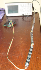
Hi there, Ive developed a16 colour (using red/green tricolour LED) linear display strip. It features 4 i/o bits per LED. (Off, plus 3 levels of Red, 3 levels of Green, 3 levels of Orange, 6 in-between shades of orange) The linear strip is designed to be mounted above/behind a midi keyboard key array. Possible display modes include noteon/off monitoring and showing the position of keyboard splits and zones. Anyhow, once tested this will all be documented on my midibox blog. One octave requires 6 shift registers. I have drafted a strip module pcb design that covers one octave. As many octaves as required are chained together. For my own use will be 2x4 octave (2x48 notes) in 2 strips. This adds up to 48 shift register chips. So my question relates to the maximum number of 74hc595 that can be chained. I understand it is the capacitive load of SCLK and RCLK signals to each chip that creates the limit. Possible strategies: 1) Reduce the clock frequency of the SPI port. (Using DMA, this should have a very minimal, or negligible adverse effect on performance and is the preferred solution). Question: Where (in MIOS32) is the sr clock speed defined? 2) Provide a (stronger) buffered output to SCLK and RCLK (a buffer line driver at the start of the chain to drive these signals harder than the STM32 with pullup resistors.) Question: suggested device? thanks
-
Robin, have you done calculations/benchmarks/analysis to show that the conventional method of reading switch matrix's with MIOS32 is too slow for your application? I guess if MIOS is to be augmented and the effort mustered then there has to be a reason beyond just a "faster is better" assumption. The analysis needs to reveal that the alternative approach is sufficiently superior to warrant proceeding. As a keyboardist, I am familiar with the feeling that latency can never be low enough, but in fact somewhere around 6ms (or more!) is totally fine in regards to playing with feel. In other words at a certain level small changes become unnoticeable. For example if it turns out that the alternative approach yields a latency of 4 rather than 5 milliseconds then one might not divert the effort in this direction. I guess these are the considerations that run through my mind when reading this thread. Hope I don't sound negative! :-)
-
Velocity crossfade zones (for upcoming blog article)
Duggle posted a gallery image in Members Gallery
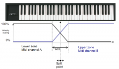
From the album: Duggle
© © Duggle 2010
-
From the album: Duggle
© © Duggle 2010
-
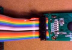
Detail (note twist required with this particular display)
Duggle posted a gallery image in Members Gallery
From the album: Duggle