

Duggle
-
Posts
992 -
Joined
-
Last visited
-
Days Won
5
Content Type
Profiles
Forums
Blogs
Gallery
Everything posted by Duggle
-
From the album: Duggle
-
MIOS32: Velocity crossfaded keyboard zones (code included)
Duggle posted a blog entry in Duggle's Blog
Simple keyboard zones Rather than have the whole keyboard output the same midi channel (hence same sound) we may want to have "left hand ->Bass" and "right hand -> Treble" parts. This is accomplished by having a "zones" in this case upper and lower parts of the keyboard separated at a certain note on the keyboard ("split point"). A simple keyboard zone split is simple to define: for example output note numbers above a the split point on a different channel. Velocity crossfaded zones Rather than a sudden boundary dividing keys into one channel or another, crossfaded zones have an overlap. The incoming notes have their velocities scaled according to a curve best shown in a diagram: Implementation A simple split my be accomplished with a call to the following function with received midi package before sinding it on: //*********************Simple split************************************************************* mios32_midi_package_t split(mios32_midi_package_t m_p, u8 splitpoint) { if ((m_p.type == NoteOn || m_p.type == NoteOff)&& m_p.note>splitpoint) m_p.chn++; //output on next channel return m_p; } //********************************************************************************************** The lower zone is output on the same channel as the input. The upper zone is output on the next channel. Velocity crossfade zones are done with calls to two functions: upper and lower. //********************Upper keyboard zone******************************************************* mios32_midi_package_t VelocityCrossfadeUpper(mios32_midi_package_t m_p,u8 sp,u8 size,u8 chan){ m_p.chn=chan; //route to new channel regardless if (m_p.type==NoteOn){ //other event types are passed through if (m_p.velocity==0) return m_p; //note offs (vel==0) get passed through if (m_p.note>(sp+size/2))return m_p; //above split region so return unmodified if (m_p.note<(sp-size/2)){ //below split region so return velocity 0 m_p.velocity=0; return m_p; }else{ //within sp + or - size/2 so scale m_p.velocity=(m_p.velocity*(m_p.note-(sp-size/2)))/size; //scale the velocity return m_p; } } else return m_p; //NoteOffs (or other events types) get passed through } //********************************************************************************************** //*******************Lower Keyboard zone******************************************************** mios32_midi_package_t VelocityCrossfadeLower(mios32_midi_package_t m_p,u8 sp,u8 size,u8 chan){ m_p.chn=chan; //route to new channel if (m_p.type==NoteOn){ if (m_p.velocity==0) return m_p; //note offs (vel==0) get passed through if (m_p.note<(sp-size/2)) return m_p; //below split region so return unmodified if (m_p.note>(sp+size/2)){ m_p.velocity=0; //above split region so return velocity 0 return m_p; }else{ //within sp + or - size/2 so scale m_p.velocity=m_p.velocity-(m_p.velocity*(m_p.note-(sp-size/2)))/size;//scale the velocity return m_p; } } else return m_p; //NoteOffs (or other events types) get passed through } //********************************************************************************************** Application The following application applies the crossfade split to note events on any channel of any (or all) ports. Midi packages on USB0 are not processed to keep the port available to MIOS Studio as a development convenience. Usage Inputs notes on any channel CC#110: Splitpoint location (note number) CC#111: Split size (distance in midi notes) Outputs ch1: Lower zone output ch2: Upper zone output //***********Velocity crossfade zones app example****************************** void APP_MIDI_NotifyPackage(mios32_midi_port_t port, mios32_midi_package_t m_p) { static u8 splitpoint=60; //defaults static u8 splitsize=12; //defaults if (port!=USB0){ //reserve USB0 for MIOS Studio comms //send lower split MIOS32_MIDI_SendPackage(port,VelocityCrossfadeLower(m_p,splitpoint,splitsize,0)); //send upper split MIOS32_MIDI_SendPackage(port,VelocityCrossfadeUpper(m_p,splitpoint,splitsize,1)); if (m_p.type==CC){ //update split params switch(m_p.cc_number){ case 110: splitpoint=m_p.value;break; case 111: splitsize=m_p.value;break; } } } } Pictures and code © Duggle 2010 -
Trouble with USB enumeration (winXP laptop)
Duggle replied to Duggle's topic in Testing/Troubleshooting
Hmm... mine is a HP as well. I'm thinking that instead of opting for "Automatic" but instead "Install from location" which contains an *.inf file then it would be possible to force the correct binding, but his is beyond my expertise. -
This is what worked for me: 1) Download and install openocd 0.2.0 (earliest version after 0.1.0 available as prebuilt *.msi. Btw, 0.1.0 is preferred for compatibility with the mios provided scripts) 2) In Program Files\OpenOCD\0.2.0\drivers is a folder contained in ft223.zip, unpack this folder to a temporary location. 3) Attach the JTAG key to USB. After "Found New Hardware" wizard, install from the location of the folder in step (2) 4) Invoke OpenOcd with the following command line: openocd -f %MIOS32_PATH%\etc\openocd\interface\amontec.cfg -f %MIOS32_PATH%\etc\openocd\target\STM32F10x.cfg 5) Continue to follow Thorsten's guide in uCApps->Bootloader->MIOS32->Experts guide->"Accessing the core via JTAG"->"Quickstart DOS" Hope this smooths the way for someone!
-
Connecting a CORE_STM32 to a Jaycar QP5518 Character LCD
Duggle posted a blog entry in Duggle's Blog
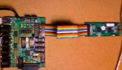
Jaycar is an electronic component retailer in Australia. They have stores in many locations and for this reason are a convenient source of parts. The QP5518 (Jaycar's cat. number) is 2x16 yel/grn LED backlit display. It is pin compatible with the Core32 EXCEPT VDD AND VSS NEED TO BE SWAPPED. Why this is the case I have no idea, but it's sure to bring some to grief. FIX: Simply peal back wires 1,2 of the ribbon used and twist it before crimping the IDC connector at one end. Thats Brown and Red in the picture below: Additionally it is not necessary to connect pins 15,16 from J15 (backlight LED drive pins) as this display has the backlight LED wired with series resistors to Vss and Vdd. The default brightness is quite good, I found. It is possible to remove the LED connections to Vss,Vdd on the LCD PCB and use the variable brightness LED driver of the Core32 J15 pins 15,16 instead. -
Trouble with USB enumeration (winXP laptop)
Duggle replied to Duggle's topic in Testing/Troubleshooting
Good news is I'm able to happily learn/develop mios32 stuff on my desktop machine. Bad news is I still cant run the cores on my laptop . Ive tried uninstalling using this: USBDeview.exe from http://www.nirsoft.net/utils/usb_devices_view.html When I reconnect the core32, I get "found new hardware", and when I choose install automatically the only file transferred is "ksolay.ax" when I do the same on my desktop machine I notice "stream.sys" getting copied. So it seems the core32 on my laptop is being recognized as something it isn't, or something else. I tried uninstalling device drivers for the usb ports themselves without success. -
Hi, Ive built two core32 PCB's which work fine on my WinXP desktop PC (BTW; thanks TK, SmashTV, and contributors!) However, on my laptop the cores enumerate as "USB Audio Device" in device manager, but no midi ports are visible to applications. I first connected the cores using USB power and I suspect something went wrong with the initial driver-to-usb-port binding. Ive selected "uninstall" and upon reconnection the Found New Hardware dialog appears, I choose automatic installation. No change. I'm now using external power with the laptop. Is it possible this (poor usb bus power)corrupted the initial driver binding? How to change/reinstall the driver? Many thanks [edit]to clarify: the core32 is powered by external power adapter now, but not initially.
-
MIOS32 LCD driver: does one exist for ST7565P
Duggle replied to Duggle's topic in MIOS programming (C)
Thanks so much! It seems all very straight forward. Looks like smash's shop is backed up a little, so I wont be able to report success until I get my cores. -
MIOS32 LCD driver: does one exist for ST7565P
Duggle replied to Duggle's topic in MIOS programming (C)
OK (looking at the examples I have) Ive convinced myself they use the same instruction set, I'll wire one up and try the existing DOG code. For convenience, is there a wiring diagram like for the other displays documented uCapps/LCD Module? thx -
MIOS32 LCD driver: does one exist for ST7565P
Duggle replied to Duggle's topic in MIOS programming (C)
Awesome, thanks. I have good reference code for the display I'm using so I'll look at the initialization. If I find differences I'll eventually commit the modified version of the driver to the repo. thx again. -
Hi TK and All, well Im back after some years! (Very excited regarding the amazing state of mbhp development, congratulations!) I have my core32's pcb,parts,JTAGtiny on order and have installed and tested the build tools. I'm interested in developing a driver for a ST7565P based graphic LCD display. First of all is there an equivalent driver already? I want a starting exercise (on mios32) with a clear goal, and I have access to many of these displays. It would seem that following the pattern of the existing drivers is a fairly straight forward process for writing support for a new one. I guess the only thing that complicates it slightly is that the variant display device I have (CV9007, based on ST7565) has SPI interface only (2 wire plus 3 control lines). Is it possible to easily support connection to any of the available SPI ports (of the 3 available)? Ive been pouring over the docs and getting familiar, I guess I'm fishing for any advice you guys may have for me at this point. Thx,Cheers.
-
Thanks TK, yep, it really was easy. Now I understand how the LED map works. Never had ocassion to look at it before. Now I have a really good reason to. I just bought a PowerCore MkII DSP card and Access Virus synth plugin. Awsome. There are about 200 paramters to tweak and I have come up with a novel way utilising the MB64 with colour coded banks (coloured LEDs) and coloured printed labels. I'll post pics soon, cheers
-
Hi fellow Midiboxers, (it's been ages...) This should be easy, but I've searched the forum and inspected the source and I'm not sure of the simplest way to do this: I'm using special function {FF 02 0n} to use buttons 1..16 to select banks. I want the LED's to reflect the current bank. My hardware setup is fully standard. Thanks for any help! Doug
-
Hi, I'm through my exam period so I have some time. I did some more work on this since the version Thorsten tested. I do plan on finalising a mode for use with MBSEQ (single ps2 keyboard events activate midi-key combinations for MBSEQ remote) then releasing the design and firmware for anyone interested. At the moment there is a bug that occasionally causes the a PS2 port to stop functioning (quite rarely). Until this is fixed I would not use it for live performance! ;) To recent posters on this thread (sorry, I've not been here for a while...) personal message me and we can arrange for a beta version test. cheers
-
hi, Maybe using MidiBox CV to control a PWM motor drive would suit you're application. ( this would mean midi CC value would control motor speed, if you want to control motor position then the CV could drive a servo) cheers
-
Hi , the PWM frequency of a 20MHz PIC with 8bit resolution is very high >64kHz if my memory is right, (the datasheet will confirm this) so the RC can be made very short. cheers
-
Hi, If I may suggest: Implement a 8 bit wavetable in the ROM internal to PIC#1 (using "retlw" instructions) and output an analog waveform using PIC#1's CCP1 and CCP2 PWM output. This allows for 2 channels. Implement the amplitude env+mod with a simple VCA with control voltage coming from an Aout Channel associated with PIC#3. This removes the need for PIC#2 and external ROM and DAC. You could duplicate PIC#1 for more voices. cheers
-
hi, 0-5V CV can be derived from the audio output of any theremin (if it does not have CV outs). There are IC's that convert RMS of AC signals into DC signals that can be set to 0 to 5V range. Also frequency to Voltage converter IC's do the same for frequency. This way 2 CC's can be derived from any theremin output. cheers
-
hi, Depending on how fancy you want, there are various ways to go. One way is to use the amplitude as you suggest by precision recitifying the audio output and lowpass filter to give an envelope signal 0-5V. This would provide info for noteon gating and velocity. If you amplify the oscillator output to 5Vpk square wave, this could be fed into the PIC CCP input to get a rather accurate pitch determination. Program logic could be used gate notes with an initial velocity and track their pitch with Pitchbend midi messages and even modulate a CC with the volume envelope. cheers
-
hi, I think you make a valid point. As the cathode driving pin reaches its maximum current sinking of 25mA or thereabouts the voltage on this pin will increase which means less current through each LED. If this is the case, then the brightness of LEDs in a column will gradually decrease as each additional LED is turned on. It may be not very noticable. (btw; I think the LED rings can operate in different modes so you can have single dot being displayed if you want.) two solutions I can think of: 1) use high output LEDs (say 100's of mcd) and increase 220R to 1.5k -> (5-2)/1.5k=2mA per LED 2) put a darlington array such as ULN2003 in front of the column driver. You'd have to invert the DOUT signals to these driver lines in the firmware (not hard to do, I believe). cheers
-
1) standard monolithic ceramic caps are rated at about 50V which is plenty. 2) Are electrolytic (they have large cyclindrical appearance). "+" on the schematic is the positive side. Make sure they are in the right way!!! The marking on the case of the device will (most likely) have a minus ("-") sign pointing to the opposite end from the positive side. If you put them in the wrong way they'll go pop! 3) A fuse is not a bad idea. Put it in series with the AC input (connected between J1.1 and the rest of the circuit). The value of the fuse should match the rated current of the plug pack you intend using (i.e 1 Amp plug pack -> 1A fuse) cheers
-
@airmailed Perhaps go to local electronic store where you can browse for a plug/socket combo that seems suitable. The one near where I live is Dick Smith (.au). and they have a wide variety of connectors even though theyre really a consumer product retailer. There are various DIN plugs/skts with various numbers of pins and I'm confident they'll be on sale for a long time to come. @rasOfir My recommendation is that you purchase a cheap 12VAC 1A plug pack and follow the circuit that was posted in this thread. It's cheap,neat,safe,elegant solution based on absolutely tried and true methods. If you are still confused or run into trouble along the way we can help in this thread (I promise!). cheers
-
hi airmailed, The PSU you have sounds quite neat. Pity the connectors are the same as midi. I guess you could rewire the plug with some low cost unusual multipin plug/socket if you want to be really safe. You can then disregard the need for power in protection as it will be impossible to plug the wrong thing in! Its easy to check if it's unregulated: under no load the output will be about 20% higher than rated, and at full load the voltages should be fairly close to the designated voltage. If the voltages are within 0.5 Volt of the designated voltage under no load then you can assume that they are regulated and therefor you should bypass rectifiers and voltage regulators on the core and other circuits. btw: the thing that makes voltage regulators get hot is when the input voltage and load current is high. cheers
-
hi, Using SMD resistors, the R2R DAC's resistor chain should take up no more that the same real estate as the Dout SR. I suggest folks dont be scared of SMD. Its really not that hard to handle. If vision is a problem there are illuminating magnifiers that overcome this problem. SMD (particularly discrete components) have some distinct advantages: -no holes to drill or stuff components into -no leads to clip -much less board space required Heres my tips: -resistors can be nudged into position with tweasers or jewellers screwdriver -surface tension of molten solder can actually be used to "suck" resistors into position. -if the resistor is not correcty in position, apply heat and nudge into correct location, then solder the other side. With a little practice the process can be really efficient, and the results are really pleasing (and tiny!) cheers
-
@stryd_one:http://www.rockby.com.au/index.htm checkout "clearance" pdf. @airmailed: to my mind having to have multiple plug packs connected to your box is messy and to be avoided. Anyhow, is the 5V supply regulated? if so, it is a little difficult to come up with a protection scheme that is robust and guarantees to protect the core, given that the bridge and regulator will need to be bypassed. The danger is if the wrong kind of wall wart is plugged into your box. A parallel zener diode will offer some protection, but if say the wrong polarity, or AC instead of DC, or wrong voltage is plugged into your box, the zener will clamp, protecting your pic, probably go short,(depending on the wattage of the zener and time), this short will fry your wall wart. If you employ a series resistor to limit the clamping current then there will be a voltage drop which may cause the core and associated circuitry problems under normal operating circumstances. The most failsafe power input stage protection is already in the core design, namely bridge and voltage regulator, and supplying at least 7.5V. If the bridge is replaced with a link and diode like in the circuit posted then the required input voltage is a little lower. If the plug pack is not regulated, then it is normal for the voltage to be somewhat higher and it may drive the regulator output to 5V (or close enough). hope this is clear, if not please ask. cheers   Â