

NorthernLightX
-
Posts
891 -
Joined
-
Last visited
-
Days Won
1
Content Type
Profiles
Forums
Blogs
Gallery
Posts posted by NorthernLightX
-
-
hey NLX,
it should work.. ive read that somewhere.. try it out.. it should probably work.. dunno if its that handy though..
Why wouldn't it be handy? I'll use 10 buttons too, and place them in 2 rows. (I already have the LCD, and would like to use more than just 2 of the 4 rows). Perhaps one row above and one below the LCD.
-
Hi moogah,
I'm very interested how your developments are going!
As soon as my SID is finished I was planning to build a box with an AOUT and some filter modules inside (for example TK's CEM3378 filter), distortion would also be very welcome for that project, so if you would share your aquired knowledge I'd be very happy :-)
Cheers, Alex.
-
I find 31$ pretty expensive. I bought a few some time ago from Germany, and sold them to board members at my buying price+shipping etc. And that was 12 euro a piece...
-
Hi guys, could a 4x20 display (standard hitachi interface) be used with the same trick? I mean would the text wrap around and would the 5 extra functions be listed on row 3 and 4?
I wired it up once, and when the bootstrap was active it displayed the famous blocks on rows 1 and 3. I hope this is possible! :-)
-
If it's a PS/2 keyboard search for "PS/2 keyboard" on these forums :-)
No, it's USB.
-
If you ever heard a C64 speak you know it has to use all 3 voices to produce something recognizable as speach. To try to wavetable something that copmplex is either masochistic or crazy. I believe the C64 samples where digitized via special software (I think conversion to wavetables is exactly what the digitizing did), if you could just do that and then convert it to a patch loadable by MBSID, you've got yourself an analogue sampler 8)
-
Thanks for the replies!
I've spoken extensively on MSN with Mendelt, and that cleared up quite a few of my questions about the PSU. Will go and fix the thing tonight.
manvsmachine: thanks for the link! I don't really need the 5A though, so I doubt I'm going to use it. it's in my bookmarks now anyway :)
[dutch] En ik spreek best redelijk Nederlands, dus dat is geen probleem ;) [/dutch]
-
Hey Slorrin, I said Parts Archive, not Parts Questions :D
Nevermind ;)
-
I don't see why this would not be allowed on the forum, everyone wants SID chips, don't they? So the community can only profit from another source of fresh SIDs. Unless they're priced too high, but then the seller is going to have a hard time selling them anyway.
I only think you posted on the wrong board, there's a special area for this kind of posts called Parts Archive. I think the moderator will move it there shortly :-)
Cheers, Alex.
-
I was considering the use of a single-dimension LED sensor, EG just a line, not a grid.
Doesn't have to be a straight line either... It could be really useful, think of it for replacement of pots/encoders and LEDrings... You could just have the LEDrings...
Wow, that's a pretty cool idea! I have a digital dashboard in my old car, and it would be awesome to recreate the rev-curve in leds on a midibox, which you could operate bij hovering your finger over it! Now I know what I'm going to do with my spare 5mm LED's 8)
-
OK, thanks guys, the resistors are going to be removed!
Keep you posted...
Cheers, Alex.
-
wow man you have to lose R1 and R2....They are probably both open now anyway if they were 1/4 watt.
Why are they there?
I would also check your filter caps, C1 and C3, as they might not have recovered so well from a load like that. (something's gotta pay when you flame up a wire like that, I would bet it was not just the resistors.) If you don't just swap these parts you should at least check for excessive AC ripple on your DC output lines.
Best Regards
SmashTV
Hi Smash, thanks for your reply!
The resistors are in the schematic for some kind of protection, my first caps are rated 4700uF, my dad suggested that when using caps that big you need to provide a "load" to decipate the spiked generated by the trafo when turning the box on. I've measured the 9v circuit with and without the resistor, and it made no difference for the voltage.
The resistors are 3W and they come from his leftover military stash (must be over 40 years ago, when they still made stuff that could take a beating ;) ), I desoldered the one in the malfunctioning branch and measured it: it's ok. I don't know how to measure/check the caps, but they are rated 40V, I don't think they've fried either. What I initially thought was that my rectifier had taken a beating as it only read 10v when being supplied with 8,5ac, but it seems that it needed a little time to recover, 'cause now everything is about fine again (thay way it used to be anyway).
I agree with smash, if r1 and r2 are supposed to be bleeder resistors then they would need to be at the output of the power supply.(worst case 13v/3000ohms=.0043A or .056W I don't think the resistors blew). But there's some other problems. The power transformer outputs 9 vac and 5Vac at the two secondaries. That'll be about 12.6 Volts and 7 volts after the rectifiers. (it's been awhile so correct me someone if I'm wrong) Full wave bridge rectification is the ac x 1.414. also in your circuit as shown above, you have a 9 volt regulator supplied with a 7 volt source, and a 5 volt regulator supplied with 12 volts, switch the secondaries or the regulators. Also the way the two supplies are built, they are separate entities, you have a ground wire connecting to both supplies via the led, pick one side or the other not both, although I don't think this would cause a problem. More than likely you've gotten your gnds and B+ crossed somewhere and perhaps shorted the supplys' outputs or wired them in series.
My buddy Willy once told me...
"Hey go for it, Chicks dig the sparks!"
Have Fun!
RoyalScam
Oops, the schematic is wrong ofcourse, switched the 78xx's ;D /schematic fixed now.
The ground wire needs to be there according to moebius, who made that clear during some very cryptic posts, but I measured the stuff and the wire makes no difference for both branches. The LED is ofcourse not used to connect both branches, the LED is connected between +5v and ground, did I make another mistake in my schematic? the dot should mean there's an interconnect between the 3 wires there, shouldn't it?
What I'm really curious about, is how much volts I should actually read on the 9v after rectifying, it is indeed a full wave bridge. I still believe the one rectifier might be faulty...
(The official formula would be nice too, because the AC input is not exactly 9v and 5v, rather 8,5v and 5,7v. Constantly trying to learn...)
Thanks for your help guys, it's appreciated!
Cheers, Alex.
-
Hi pay_c,
Thanks for your comments! Yeah, I suspected that I would need more volts on the Incoming pin of the 7809... here's tonight's story:
I replaced the 1,5Kohm resistors with 3Kohm resistors this evening. When I turned on the device I got a surprise, though an unpleasant one....MY FRIGGIN' BOX CAUGHT FIRE!!! :o :o :o
One of the wires just totally melted on me, that was a pretty lightshow by the way. I immediately turned the power off and checked if anything got damaged, and fortunately every component was in the same state it was before the meltdown (I won't say they're all OK because I still don't get the voltage i've read earlier, but this could be due to the absense of a "load").
So, I replaced the cable, and tried again.... no fire this time, pffff... started measuring again... WTF!? the output voltage went further down! only 7,75 volts instead of 8!? Now I'm really pissed....
I decided this was not a good day to continue fiddeling with the 9v branch, so instead I made a nice powerLED in my box. That worked from the start, happy me!
Then I drilled some holes in the bottom of the box to neatly attach the PSU. I also made some spacers so the board is elevated from the floorboard, that all went pretty well.
To finish off the day I wanted to view my LED one more time :-) ...still beautiful. So, I don't know why, but I took the multimeter one last time, and behold! 8,5V on the 9V branch! Still not enough, but at least better than what it has been so far with a "load" connected. Still, the 7809 is only supplied with 10 to 10,5 volts. I'll need to add windings to my trafo to solve this problem, but that type of wire is not so easy to get. I'm going to buy a second trafo (same type of course) and did as I did with this one: unwind one of the windings so I get a 8,5 / 5,7 trafo, but then I have some spare wire to make extra windings to the 8,5v side. I'll wind it up 'till it delivers about 9,2 Vac, that should be enough for the 7809 to do it's job after it's rectified.
My final schematic:

Cheers, Alex.
-
It is possible with some older ATX PSU to modify them. If you do that it acts like a normal power supply without a switch. We use them at school as power supply's ;D
You can, but keep in mind that the trafo's used on those are often very small, so if your box draws some current they'll not be able to cope...
-
All computer power supplies are switching, or so have I been told. Those are useless for midibox. You need 12v for your MF module, so the C64 PSU is not an option for you. I got my trafo from a local "dump-shop", where you can buy second hand electronics and obsolete army stuff. Mine is still not working either, but for different reasons. If I were you I'd check if such a shop is in your vicinity. Good luck!
-
Some more specs and a picture of the LCD:
Graphic LCD (CFAG12864B-TMI-V)
* White Edge LED Backlight
* STN Negative, Blue
* Transmissive -20 +70 deg C 6:00
* Negative Voltage Generator
[edit]
removed pic, is now in the startpost
[/edit]
-
Hi guys,
I have some unfinished MBHP boards for sale, and some other stuff too. Of course I asked TK's permission before putting the modules up for sale ;)
All boards have originally been bought from Mike and are untested unless specified otherwise. I wasn't a solder-god when I did these (and neither am I now) but the parts will not fall off by themselves. No guarantees are given that I used the correct parts though, you'll have to check everything yourself!
All prices do not include packing and shipping, these costs have to be quoted per individual. I'm located in Holland, if you like to collect your parts you can pay cash on collection. For sending, the only payment I accept is bank/wire transfer in advance. No CC or Paypal or anything, I don't have it, sorry.
What I have on offer:
1x DOUTX4_V2 without ICs. Resistors are not stuffed, this is not a bad thing, as you need to calculate the resistor value your LED's need. The recently introduced bypass caps are not yet soldered. Some of the isolated jumpers on the bottom are also not yet in place. - 4 euro

1x JDM_V2 fully stuffed and ready to use (for PIC16F. I never got it working myself due to a low voltage on my PC's serial port. For PIC18F you need to solder an additional 10K resistor to the board). - 2,50 euro

The other parts I'm selling:
60 Waldorf Q button caps. These babies are oval shaped, so good luck with the drilling of matching holes, that's the main reason I'm parting with them. They're all yours for 5 euro.

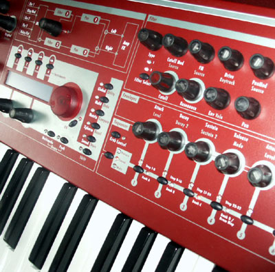
Image of the Waldorf Q: (Yes, those encoder caps are the ones TK uses on his MBSID. No, I'm not selling mine :P ;D)
2 PIC 16F877-20/P - Leftover from the old days when Midibox still ran on these. Still useful for eDrum project a.o. These are virginal as far as I know (never been burned). 5 euro a piece

1 CrystalFontz graphical LCD. Type is CFAG12864B-TMI-V - white on blue backlight. Looks really cool. Resolution is 128x64. it's new, never seen any soldering outside of the factory. 25 euro

What I am looking for (so we might trade):
3 (or max 5) detented rotary encoders
1x BankstickX8 module (soldered or unsoldered, without ICs because I have those already)
1x AOUT module (soldered or unsoldered, not AOUT_LC)
Maxim MAX525 IC
Maxim MAX6007B shunt
CEM3378 or CEM3320 ICs
or anything else I might find interesting.
Write me a mail at northernlight (at) zonnet (polkadot) nl or a personal message on the forum if you're interested. Most prices are negotiable, especially when ordering more than one item.
Cheers, Alex.
[changelog]
12-3-2006 - Decided to hold on to the Core with LCD cable, a different core is for sale now. Also decided to hold on to the LTC, 1 DINX4 and 1 DOUTX4. Decided to sell one more SID for 6581. Changed text at various items with more info. Picture added with each individual item. Removed big picture. Added section "What I'm looking for".
23-3-2006 - Sold 1 Core, 1 DOUTX4 and the DINX4. Added CEM 3320 to "What I'm looking for" section. I desoldered more stuff from the SID boards, they're more or less skeleton right now, apart from the filtercaps they're now suitable for both 6581 and 8580. Don't have a new picture yet, so temporarily removed them. I might hang on to one of them though.
-
Done some more testing:
I borrowed a laboratory powersupply from one of my very friendly neighbors, and tested at what voltage the 7809 actually begins to supply 9v again. That was when it's being supplied with 11,5Vdc. The only real change (beside the heating of the parts when desoldering and resoldering again) is the resistor value, at first that was 2x 1,5Kohm in series so effectively 3Kohm, and this time I used a single 1,5Kohm resistor per branch (because the serial chain solution just didn't look very pretty to me). So, for some further testing I aquired a set of 3Kohm resistors, and I will solder these in place sometime this week. I'll let you guys know what the results are.
If the 3Kohm resistors don't do the trick I'm going to replace the 7809 with a fresh one, and if that doens't do the trick either I'm going to add windings to my trafo to crank up the voltage...
Cheers, Alex.
P.S.
If someone who understands electronics better than I do, which probably counts for everyone 'cause I'm a real n00b, feel free to comment on my actions, or to advise on actions to take!
-
Lijkt me perfect voor een MidiBox FM of CV met ingebouwde filtermodules. 25 euro lijkt me niet te duur. Heb zelf (nog) geen interesse, eerst de SID maar eens afkrijgen.
Gr, Alex.
-
I don't see why this would be useful, you can already customize your control surface any way you want, why add some 150$ thingy with no extra functionality?
-
About the troughput: USB's 480 Mbit is theoretical, where the 400 Mbit is actually acievable with firewire. Also I've heard some stories that claim USB is far less stable. There are some things in the core design of USB that make it less useful for (high-end) audio applications than firewire, which was designed for audio/video production. I myself would choose firewire, if I would have to. There is only one thing better than both, and that is a dedicated PCI card as an interface to your break-out box or rackunit.
Just my €0,02
-
""Common Ground" is something that any decent Midibox should have. There might be some on the eBay and some on the "Request to sell".. Please - don't trust on these - If not approved by Thorsten -none of these have the "Common Ground" the Midibox has!"
Do connect the grounds.
M
Damn, I just bought myself a bucket of common ground and put it in the box.... Couldn't you have warned me earlier???
No room for SID and Core modules now either... ;D
-
Hi all,
I have a problem with my PSU. I made a prototype board, which gave good voltages.
http://home.quicknet.nl/qn/prive/alex.span/midibox/psuboardtop.jpg
So I desoldered everything, and made a new board, a little prettier.
http://home.quicknet.nl/qn/prive/alex.span/midibox/psuboardnew.jpg
The only problem now is that the 9v I measured on the old board, now measures 8v. Right before the 7809 I still measure 10,5v, this is the same as on the old board. Has the 7809 been too hot perhaps, bacause of soldering and desoldering, or do I need to seek the cause in a different direction?
Cheers, Alex.
-
I believe any LED needs a resistor before connecting it to current. Look at the DOUT board, all those resistors are there for the LEDs they supply.
Cheers, Alex.
2x40 LCD's ( ... I hope)
in Fleamarket
Posted
You can keep them.