monokinetic
-
Posts
326 -
Joined
-
Last visited
-
Days Won
5
Content Type
Profiles
Forums
Blogs
Gallery
Everything posted by monokinetic
-
Hey creatorlars, thanks for coming up with this, I want to trigger some diy analogue drum synth stuff from my MBSeq as well, so this will really help! Please do document it on the wiki, I'm sure others will find this useful as well :) David
-
Got them yesterday, whiter than white. Cheers for arranging this one nils (where's that beer smiley gone...) David
-
Hiya Stryd, As ever thanks for taking the time to read such a detailed post and trying to help, it's most appreciated! Aha there's something new to me. Ah well, one lives and learns :) Luckily I always buy 2x parts in group buys so looks like I will have to order the nice solder screened OPL PCB from Smash for attempt 2..... Yup but I'm pretty sure I implemented this. (Will double check tho just for my sanity). Just as a matter of interest is there any way to verify the crystal oscillator other than a scope? Well I'm off to buy an ankle strap before I kill anything else :D Thanks Dave
-
Hi seppo and stryd, Well I have been working on MBFM on and off for a couple of years now :) [in fact i just checked through the forum and my first message re: MBFM is from 2005, yikes!] I'm in no way criticising the original OPL3 board layout, just exploring ways of finishing this project before 2010 :D Anyway, a brief recap: my YMF and YAC chips are from the first bulk order. I have the original OPL3 board hooked up to a V2 core. My PSU is an AC wallwart hooked up to the appropriate caps and regulators mounted on veroboard. I can upload apps to the core fine, so I'm sure MIDI is working fine. The core has the latest version of MIOS and MBFM. Running the MBFM interconnect test app, I'm sure that the core is sending the appropriate signals to the OPL3 board. The problem is that when running the MBFM firmware I get absolutely no sound from the OPL3 board. Simple as that. The LED on the OPL3 board comes on, there's + and -12V at the power input on the OPL3 board. I've tried two batches of TL074s (hadn't realised they could be sensitive to static the first time I built the OPL3!). Still nothing. My current crystal oscillators both seem to be from NOS, I've not got a scope so I can't think of a way to test they are actually working. Any suggestions how to rule this out? Unfortunately I can't find the appropriate crystal oscillator here in Prague, so I'm contemplating building the oscillator adapter from gyorgy's page: http://web.t-online.hu/gyurek/midibox.htm#oscillator Anyone explored this option? My current OPL3 board is from Mike, so there's no solder screen and some of the tracks are really close together. Although I've been over the board with a magnifying glass and scraped every single possible solder bridge, still not a single sound. I'm currently considering either ordering a new OPL3 board from Smash with solder screen to see if that makes a difference, or trying the alternative layout I originally mentioned. The reason for this is that the tracks seems to be more spaced out and therefore less chance of bridges.... what do you guys think? One thing that I did do when testing was to measure the voltages at the YMF chip and YAC chips. Obviously I was very careful, but is there any chance these could get killed by static? Well, as you can see, now I'm pretty stuck. So any suggestions more than welcomed :) TIA Dave
-
Wow, I thought I was the only one not doing MySpace. Looks like my fellow boxers are with me :) But seriously, anyone? D
-
Hi, I'm contemplating building up a MBSID, combined with a MB_AOUT_NG for hooking up to my modular (which is still laying on the bench in various pieces!). I'm not planning on using any SID chips in there (well for the time being anyway!). I've given the user manual and the forum a good read through but I have a few remaining questions: I know that I can take 5 (maybe 8 in the future?) analogue signals into the MBSID, so I can interface with CVs on the modular (which sounds great!). But is there any way that I could take some additional digital triggers into the MBSID? My idea was that I would like to synchronise some analogue sequencers which supply 5v timing clock triggers to the arpeggiators etc on MBSID. I know in terms of hardware it's just a case of using another DIN module, but can the firmware handle this (maybe if not now how about in the future?). It seems to me that I get 8 CV outs per core. If I wanted to get really fancy and have more CV outs, could I use another core slaved via MBNET? TIA Dave
-
Hi, After untold troubles with my OPL module I am contemplating the alternative layout on the wiki, here. But the links give me a 404 (see stryd's opinion on offsite documentation!). I however do have the files downloaded already :) My questions are: Has anyone actually used this layout successfully? Has anyone got a MySpace account where they could ping selfservice, the guy who did this layout, so that I could ask if he minds me putting it on the wiki? (sorry but I'm boycotting MySchmace) TIA for any help (hoping that some others get on board with MBFM so I can get answers to my troubleshooting questions :D) Dave mK
-
OK I was going to write drool as well then I saw the zoom view, drool doesn't even cover it ;) TK you really aren't helping my insomnia at all :D Off to whistle "I'm so excited...." D
-
Compiled, uploaded and tested. Works nicely.... (Thanks * 1million)23 ;) Dave mK
-
I totally understand, it's brilliant that you took the time to implement these at all. A millions thanks, as always :-D Dave mK
-
Glad you like the suggestion, I was originally going to post this in the thread you mentioned but I decided I shouldn't hijack. Thanks for the pointer though :) Ooops I meant the Track buttons, sorry. I won't have group buttons till I finish my second Seq.... I think a dirty solution for the time being while we wait for MB Seq 4 going public would be great. As long as it doesn't take lots of development time away from Seq 4 ;) Best Dave
-
MB-SEQ V3/V4 Control Surface PCB and matching case
monokinetic replied to Wilba's topic in MIDIbox SEQ
aha, after the 14th page my focus on the topic title must have waned ;-) Cheers, but I have had a Seq running for the last year or so on MIOS, I'm looking forward to having MIOS 32 for my second Seq! Dave -
Hiya, This weekend I had another long MB Seq session, TK the Seq is one of my favourite devices - thanks a million :) After the marathon session (which, when I had a mild headache in the morning, reminded me I need to dim a few of my LEDs with resistors!) I have a few suggestions and would be interested in how other Seq users feel about them: I think the Mutes page would be more useful if it were possible to create groups of mutes, so that multiple tracks could be switched on/off with one button. My idea was to have a function where if one of the group buttons is held down and then the GP buttons are used to unmute/mute a track, this track is added to a mute group, which can then be toggled using the group button. I think this would be especially relevant when MB Seq 4 arrives and we have untold tracks to control. Anyone else think this might be useful? Quite often this weekend, when I switched to the Song page to use pattern mode to quickly switch to the next part of the Song, I forgot to press Layer B. This means that the GP buttons skip to the next song and the Seq stops playing. IMO it would be nicer if the default screen element selected was the setting chosen by layer button B. Just a small detail but would make me more comfortable in a live situation.... But anyway, they are just suggestions after some major usage. Of course I would love to say that I'll look at the code but I'm busy learning Smalltalk to coax more strangeness from the Capybara ;-) maybe when MB Seq 4 is in C. .....maybe.... Best Dave mK
-
MB-SEQ V3/V4 Control Surface PCB and matching case
monokinetic replied to Wilba's topic in MIDIbox SEQ
Hi, I just worked my way through the whole thread (slow day at work, hurrah!) and I would like to ask: if you haven't already done the run of PCBs, would it be worth changing this over to MIOS 32 Core? Or at least offering some headers for the DIN/DOUT/BankStick/IIC lines so that we can easily upgrade? TIA Dave mK -
Hi TK, I had a bit of a play with this new version, uploaded the latest 3.4 Seq and tested another box as a matter of interest. All working fine here, good job - as always :-D Thanks as ever! Dave mK
-
TK: Thanks! Wow those are amazing figures! I'm even more impressed by GM5 now ;-) Can't wait to get this project up and running..... David
-
Whahoo, Christmas is here already! Many thanks to TK and Ploytec. As a matter of interest, has anyone done some measurements of the latency of the new driver? I ask because I learnt a lot about MIDI latency through a great XP tool which is here: http://miditest.earthvegaconnection.com/#about This helped me realise which of my MIDI ports has almost 10ms latency. I would be really interested if someone could post their results (if not as soon as mine is made I will post my findings!) Back to the soldering :-) David
-
IIC SD and SC lines resistance?
monokinetic replied to monokinetic's topic in Testing/Troubleshooting
Well without wanting to seem like I enjoy talking to myself....... I thought I should post the conclusion of this thread. Which is that I found the problem, I had not connected the extra cable between IIC Midi R1 and the Core J6 SI. So if anyone searching the forum later on comes across the initial problem of this thread, make sure you double check http://www.ucapps.de/midibox_seq/mbseq_v3_interconnections.pdf to ensure your IIC Midi in works ;D I'm off for some experimentation with synchronising all 3 of my sequencers, hurrah! Dave mK -
Hiya Smash, Thanks for taking the time to reply and to try if the hex file is weird etc. I forgot to mention in my original post that I am using the MB Pic Burner hardware. I have burnt the MIOS bootloader and the IIC midi.hex previously into quite a few PICs with my hardware and the pbrenner software. It seems strange to me that just this latest version of the IIC.hex is not working. Anyway, I checked out the software you mentioned but in the list of hardware I'm not sure which programmer to choose if I'm using the MB PIC burner. Anyone know? Also, is there anyone else out there with a similar setup who could confirm burning this IIC MIDI .hex file is not just a problem for me? Dave mK
-
Well today I tried to recompile the IIC .Hex file and low and behold it loads into the P44NG software fine! I knew it was a good idea to set up the MIOS development platform :-) IMO there's a problem with the .Hex in the download from ucapps because the original downloaded file is 4k and my recompiled version is 3.9K. Anyway I hope this helps anyone else who runs into the same problem. @TK and the other gurus: is it worth double checking this and if I am right about the current file being weird uploading a working version of the IIC .Hex file to ucapps? Dave
-
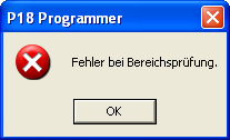
Hi, I am trying to reflash the PIC 16F88 for my IIC module and I have come across a slightly strange problem using any of the software from www.sprut.de. When I try to load the project.hex found in the mbhp_iic_midi_v1_0c.zip file from ucapps.de I get the error as seen in the attached screen shot. A quick internet translation makes me think that there could be something wrong with the IIC hex file. I can open up various other .hex files (from ucapps and others as well) with no problems. I have tested three computers now and always the same error. I also tried a few of the applications from the www.sprut.de site (pbrenner37u, pbng44 and even the P18) and none of them like this .hex file. Maybe I am missing something because my German is very bad! Could someone else please try the IIC project.hex firmware file and see if they can just open it? Thanks in advance David Moss
-
IIC SD and SC lines resistance?
monokinetic replied to monokinetic's topic in Testing/Troubleshooting
Hi Mike, Thanks for the input, interesting point, it's not something I really thought about! I will have a play with some of the options tonight when I get home from work. You also prompted me to re-read the manual at ucapps and I realised I shouldn't be sending MIDI clock in to the IIC either! However, the behaviour is the same if I send MIDI clock or notes from both my keyboard or my PC sequencer. The IIC Rx LED flashes to indicate that it has received approx 28 events. Then the light stops. Sending MIDI in to the IIC does not control things on the MBSeq (i.e. an arpeggio track etc) I'll see what this evenings fiddling leads to! Best Dave mK D -
IIC SD and SC lines resistance?
monokinetic replied to monokinetic's topic in Testing/Troubleshooting
I had a go at soldering another 1K resistor between SC and Vd, checked that I got 1500 Ohms across the SC and SC lines and tried a few goes but I still have exactly the same problem still :( I also double checked that the bankstick board and the IIC board both have infinite resistance between SD and SC when not connected to the core, individually and connected together on the IIC bus. Any other suggestions? I'm contemplating trying to flash the PIC again, long shot I know but I'm out of ideas! D -
IIC SD and SC lines resistance?
monokinetic replied to monokinetic's topic in Testing/Troubleshooting
Hi nILS, Aha, OK thanks for clarifying that. I do indeed have infinite resistance on my IIC MIDI board and the bankstick board when removed from the Core. Check! I have 2K between SD and SC on the Core. Hmmmm, I had referenced this picture when working out how to install the extra MIDI In parts on my IIC board. I am using a MB Core V3 PCB from Mike and my understanding was that this picture is referring to the Core V2 (from the note underneath it). I have R2 and R12 on the Core, so as mentioned previously I have 1K resistance between SD and VD and 1K resistance between SC and VD. So if I understand you correctly, in fact I need one more 1K resistor between SC and VD even though I am using a MB Core V3 (you seem to be talking about 3 resistors in total). Is that what you mean? (sorry if it seems obvious, it's Monday!) TIA for your assistance! Dave mK -
IIC SD and SC lines resistance?
monokinetic replied to monokinetic's topic in Testing/Troubleshooting
Hiya, I removed all of the IIC stuff from the bus, still the same 2K resistance between SD and SC. I then traced my Core V3 carefully and I cant see any bridges even with a magnifying glass :( @Stryd are you 100 percent sure there should be no resistance? I ask because on the Core schematic SD and SC both go through 1K resistors to the 5V line. So my original logic was that in fact there would be 2K resistance between the SD and SC. Or am I missing something? D