
Jidis
-
Posts
838 -
Joined
-
Last visited
Content Type
Profiles
Forums
Blogs
Gallery
Posts posted by Jidis
-
-
I just got two Grayhill 16 button keypads from an eBayer, which are much better than expected. They are 4x4 and actually have separate (non-matrix) connections. The clear caps come off so you can insert labels, but there's not much room for more than a letter or a colored square. They fit snugly, side by side, with the same spacing from button to button, so you could do banks of eights or something for rec,select, solo or mute across lots of channels in a tight space.
He's got a bunch (sells by twos/ $9.99 U.S.)
-George
http://cgi.ebay.com/ws/eBayISAPI.dll?ViewItem&category=58166&item=7524836156&rd=1
PS-- I never heard from the guy, but they showed in 9 days via regular mail.
-
Steve -
Thanks! I'll take this with me to the studio. I skimmed over the old and new schematics the other night too. I had more trouble figuring out where the different MBHP circuits connected to each other than anything else, but it wasn't hard. I'm stuck in a mix right now, so I haven't been able to do electronics out there for a couple nights. I'm anxious to see this 2x40 display in action.
I've still got stuff to do to my 64 before I can start construction. Some of the unneeded IC's will likely come out, and I need to rig up temporary switches, pots, LED's to see what I'll use.
Like you, I figured I'd end up with an 18f on here when I was populating the board, so I ground away a recess in the PIC socket surrounding the can. Should be an easy swap.
- Take Care
-
Never- Slow reply, no reply .... you've already done too much! :-*
Someone else here may even respond. It will take me a bit to refresh my memory on what I did anyway. I was so glad to see the thing work that I stuck the protoboard somewhere with a bunch of other junk and moved on to something else.
           -George
-
Id love to see it hooked up to music at a party without anyone knowing
Yeah, link it to a gain parameter on a low frequency EQ and it would sound like the worst room mode problem on earth. :-X
-
I am updating my old MB64 to MIOS standard
Cool, I guess it was Steve who was doing this!
I need to do my Greg board as well.
Steve (or anyone)- What else is done besides a pullup added at RC3 and the crystal swap for the 18f speed? I've got all the old and new schematics at the studio with the box, but no internet there.
-George
-
Thanks as usual Thorsten :)
I think I'm going to break down and make the changes tonight for the 18f (I'm running a Greg board). The layout and functions probably would have been simple enough to run a 2x16, but I may want to use the box for other stuff later. MIOS is still a bit overwhelming to me right now and I was hoping to keep everything as simple as I could. I hope someday there will be a printable PDF manual or something. There's a lot to be read here.
(to anybody) How much do I need to do to the Greg board, other than the crystal, to bring it up to date? I thought someone else here was doing that recently.
                            -Take Care
George
BTW- TK, if you read this, I got that program done a few weeks ago to snag the JLCooper record light messages with a 16f84. I ended up having to replace and rewrite most of the receive code, but I learned a lot. I did have a couple questions afterward. I'll try to go over my notes and ask them here if you don't mind.    - Thanks Again!
-
Am I correct in assuming that the old 16f firmware doesn't support the long (2x40,etc.) displays? I wired one up and get just the left side. I read on the LCD info page about the 2x20 and blank extra characters. Does this mean it's 2x16 only?
-Thanks!
-
Raphael,
Thanks! I had loads of 3904s. It looks like he even had the layout done to the pinning of the 2N part. I checked my voltages first and it all appears to work display & firmware-wise. It appears my 2x16 LCDs use pin 16 for the backlight (+) line. I thought that was 15, but it didn't hurt anything.
I have to read up on which of the socketed chips are going to what, and how many I can remove. I'm also planning to use a 2x40 display, so I need to see how the stuff shows on the screen before I can arrange my knobs,etc.
I do plan to probably switch to an 18F PIC. I Dremmel'd the 40pin socket around the crystal, so it's nice and easy to remove. This box is hopefully just doing send levels for some cue lines. I'm going to try to do a main controller afterward, which will likely use the MBHP type boards.
                                     -Thanks Again!
GeorgeÂ
-
Hello,
I've been sitting on a Greg Macmillan MB64 board for quite a while, and have finally started to set it up for a cue controller at the studio. The board is poplulated now, but with mostly empty sockets. I've blown the old firmware into an 877 (I'm running the 20MHz crystal too).
A couple questions-
I didn't have a BC337 on hand (I think it's in the LCD area) and a web search stated the 547 and a 2N2222 as subs for something. I had a 547 here. Is that OK, or should I try to dig up the 337? (most everything around here is 2N transistors)
Is there a safe "one at a time" startup/test procedure for the IC's and what is the minimum that the firmware will function properly with? I doubt I will need all the ins and outs, but the sockets are all there. I've also left the connector holes empty for now. I'm not sure if I'll use headers or solder direct and I don't want to make too much mess until I know.
                                 -Thanks All !
-
Steven_C,
I'm very interested in this as well. I'm currently starting to design my main controller to use with Nuendo and have never run anything more elaborate than a JL Cooper CS-10. I'm trying to get a feel for what parameters I want control over, and what degree of communication I could expect between Nuendo and an LC/Mackie.
I'll probably try to go with a group of knobs which map to an EQ plug on the selected channel, as well as some common channel parameters. The rest will be tool buttons and menu items. I'm assuming the VST spec. allows for some kind of return values for the plug parameters being controlled.
I'm also wondering if/how a MIDIBox could setup multi-purpose buttons with an indicator LED, like the channel buttons on the CS-10. This would obviously give me a lot more switches/controls per square inch. There are also some non-continuous controls which don't deserve individual buttons, but would need a visual indication of their current state. For instance, the HP/LP EQ filters have several curves. I'm guessing a stepped (switch type) knob would make sense with LEDs nearby to show the current filter curve. (?)
I grabbed all the Mackie PDFs I could see yesterday and I have all the individual Nuendo docs from v.1to3. It's not real easy to see what I'm up against without a working controller and a two way connection though. If anyone has any good links to manuals or anything else that might help, I'd appreciate it.
                                 -Take Care
George   Â
-
Taylor,
I was going after C at first too, but figured it would be wise to get a foundation with the assembly side of it. I just finished going through a decent book by Dave Benson and Square 1 Electronics called "Easy Microcontrol'n". That was a good start, though I'm seeing what appear to be newer writing methods in some of the assembly I find on the web. It all works the same and compiles either way. That book is only about 170 pages and they're big and spread out. With that, and some "properly commented" code from different websites, I've got a decent feel for the more basic stuff now.
I'm now looking for a good book to get next, if anyone has any suggestions. The Square 1 book reads more like a workbook. He does have others in the series, but I'm thinking maybe something heavier might be better for the second one. More like a good "reference" book with some newer PICs and their instruction sets. The Easy Microcontrol'n book deals exclusively with a 4MHz 16F84.
                            - Good Luck
PS- FWIW, I dabbled lightly in old assembler for the 68k Motorola Mac processors years ago and am recognizing many similarities. I think it's a good thing to learn no matter what processor or language you end up using later on.
-
I'm trying to learn my way around some PIC assembler and figured I'd try to make something I want. It's about as simple as it gets.
I just want to switch a single output line on and off with two specific SysEx messages. I want it to ignore all else and start with it off (low).
The messages are two JL Cooper CS-10 commands (7 bytes each)-
F0 15 15 00 12 7F F7 is "on"
F0 15 15 00 12 00 F7 is "off"
I found an ASM file for a 7 output MIDI to solenoid circuit using a 16f84 and it has helped me get a grasp on the "byte read" part of the interrupt routine. The timing and the frame check stuff has also already been worked out there. From that point, the writer goes on to number the 3 incoming note bytes and store their contents for later use. I don't guess I need any of that.
What is the obvious way of checking for this string of hex? Do I check a byte at a time as they come in and drop out if I get a wrong byte, or do I get all seven and check afterward?
-Thanks!
PS- Two other stupid questions- Does a message like this always appear in one long uninterrupted string, even if the line were active with other MIDI messages? And, is there no reliable byte to byte MIDI timing? (can you count bits through one byte into the next or do you always clock from the start bit)
-
I was going to ask about that lettering as well. Great looking box by the way! I've gotten some OK results on metal with the toner transfer method described at
http://www.fullnet.com/u/tomg/gooteepc.htm
It's not as consistent as doing the boards, but it looks like it works for certain things. I recently tried to re-label the control panel on my kitchen stove, which looks like a similar surface to Jurbo's box. I got about 95% of the label on, but kept peeling off corners and stuff. You can rub away failed attempts and retry. If (or when) I get them on there, I'm going to try to mist them with some light coats of clear acrylic or something. That may be enough protection against the "scratchability" problem.Â
-
what was the purpose of spraying the female mold with laquer?
Probably none ;)
It's been done to slicken up the mold so nothing can stick to it, and to hold the plaster together, but it's probably the wrong thing for that surface. A spray primer or something might be better suited. The plaster is sort of chunky and crumbles easily. I may also be a bit impatient about how soon I try to use it. A lot of the stuff I've done has been "one off" molding, where I don't really care, as long as I get the first piece out OK. For multiple uses, a nice solid top coat would help. I've been very lucky with not having things get glued to the molds. I'm thinking that a spray coating of PAM (cooking spray) or spray oil might work better for lube on intricate details and holes too. The petroleum jelly can get messy and globs or lines in it will transfer to the fiberglass. The fiberglass has the potential to exit the mold with a slick, smooth, paintable surface if the mold is well prepared.
I was going to mention that an "inside only" mold would probably work as well and you could still attach protrusions to create holes, etc. This would be similar to the first couple steps you mentioned, but you would build up layers of fiberglass. I *think* this is what Pierrot did with that gray box. It does seem it would involve some heavy sanding though (I think he mentioned that as well).
I'm reading over your post again. An easier means of getting a perfectly matching male/female set would definitely help. For the thing I just did, consistent thickness wasn't that important, but it does get difficult dealing with angles. For horizontal surfaces the male can be shimmed upward by an exact amount to dictate the thickness and for vertical surfaces, the sides can be trimmed by this same amount, for angles - you're left with something in between.
I only wish there was a way to label onto this crap!
     -Thanks!
-
I had a post at the tail end of Sasa's DIY illuminated buttons thread the other day about some fiberglass enclosures.
I did a small WinampLCD box as a test, which turned out surprisingly well and have some pictures and info which may be of help to someone here.
This is most of the photos, but the whole batch is at http://photobucket.com/albums/y193/Jidis/
Some of them aren't that clear, but should get the idea across. To summarize, I started with a CAD sketch of the dimensions I would require
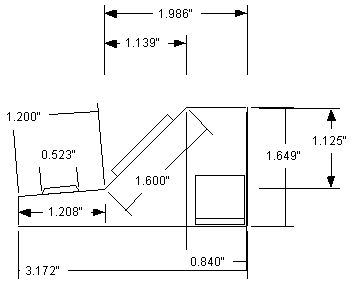
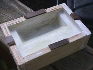
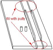
I laminated two pieces of soft (easy to work) 3/4" pine and a piece of 1/8" hardboard to get the 1&5/8" that I wanted for the height. This was glued to an oversize piece of hardboard to serve as a stop and guide, while it was in the form. I marked guide lines on the block of glued together pine and chopped away at it to get the shape I wanted. (This was actually done on a radial arm saw, but it probably could be hand cut) The corners were rounded over where need be, some with a small belt sander, and some by hand. You could also probably just smear putty or plaster into the inside corners of the female plaster mold after it dries and get the same result.
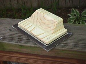
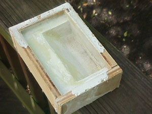
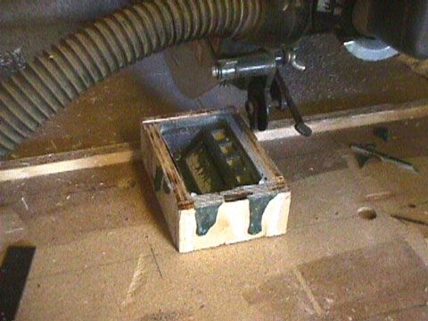
I hotmelt glued a rough plywood box together to the overall outer dimensions I needed, filled it with wet plaster, greased up the wood model with petroleum jelly and lowered it into the box. After it set, I removed the wood model, cleaned and touched up the inside mold with putty and sprayed it with clear lacquer (I had read of this, but I don't like it. I think there's something which would adhere to the plaster better).
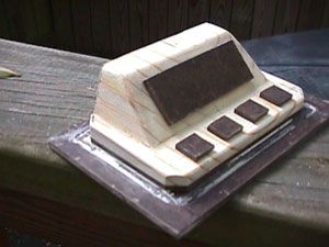
The original model would also be used for the male (inside) half of the mold. It could be shimmed upward to the target thickness for the enclosure, but the sides would need to be trimmed down to create gaps in those directions. I drew lines 1/8" from all sides and sliced that off (again with the radial saw). The corners of the male mold were also chopped around 45 degrees to allow a build up of fiberglass in the corners, which might be used to secure the bottom with screws.
Shims were glued to the box edges to create the upward gap
Now the promising part- I made paper templates of the holes I would need for my buttons and LCD, and stuck them to the wood model. I then glued pieces of 1/8" hardboard, cut to the required sizes onto the layout. The excess paper was cut away afterward.
I thoroughly greased both molds, took a couple big globs of the filler (in the round quart can), and liquefied it with resin (the big square can), mixed it with some of each hardener, and poured it into the boxed form. I think I smeared a bunch of filler on the LCD and button part of the inside form beforehand, to make sure it got everywhere.

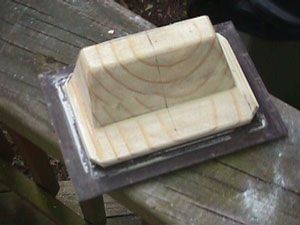
I then lowered the inside form into the boxed outer part and squashed it down until it oozed out the sides.
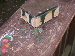
After this cured, I pried the male half out and got this.
I trimmed the excess on the radial saw out of laziness (I've done this with a belt sander before).
After a bit of sanding, I had this.
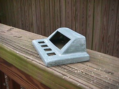
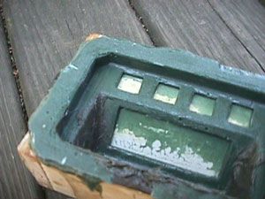
And after some black plastic spray paint, this
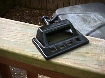
The holes are cleaner than they look in my pictures. They took nothing more than a few light strokes with a file, though I had been quite sloppy with the hardboard pieces I cut. I chopped them about 90% through with the radial saw and broke them off the rest of the way (radial saws will shoot you with small cut offs). The edges were sort of "fuzzy" and the dimensions weren't perfect. I think some thick mat board (for picture framing) might be a better choice, and it can be cut with a sharp utility knife and a metal ruler. Gluing them to the model after it had been greased was also a bad idea. It needed to be cleaned with paint thinner and sanded a bit and it still didn't hold well. Covering the area with scotch tape and removing it after the female mold was done would probably have been easier.
More good stuff-
With as easy as the square and rectangular cutouts were, I had some ideas for some others. I believe if you were to cut a series of parallel slots across a piece of plywood or something, you could insert some strips of mat board or hardboard (the width of the saw kerf) and get some nice clean fader slots. The knob/pot holes are even easier, and could be done with dowels tapped into holes. You could also produce threaded protrusions for securing the body to the bottom or PCB simply by drilling stopped holes into the model or panel. A cross sectional view of this shows a form for- (left to right) A pre-drilled standoff, two round (pot) holes and two fader slots
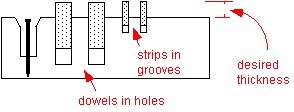
A side view of the result should be this-

The face of it would look about like this
I have not done this yet, but I don't see any reason that it wouldn't work. There's a nail in the center of the counterbored standoff hole, which would create a screw hole in the final piece. The head is just there so you can tell what it is. If anyone tries that, make sure you chop or file the head off, so it won't lock everything together.
                Hope someone can find some use for some of this
                                                     -George
PS- The frozen piezo is in that batch of pictures too, complete with rubber coating. That one was done in a 1/2" deep round hole cut with a forstner bit and the bottom corners were rounded with putty before the fiberglass went in. I filled it about halfway, let the fiberglass get hard but "gummy" and stuck the piezo on top of it with the wires in the groove. I then filled it the rest of the way and squashed a piece of mouse pad to the bottom while it was wet (to see if it would stick). The whole top half, in it's naked green color, was dipped in liquid latex to soften the feel. It triggers quite well and the mouse pad is secure enough that it will rip if I try to pull it off. If I do a batch, they will most likely be square and I may move the piezo closer to the surface. I'll probably glue the bottom of all of them to a mouse pad for isolation and center them with wherever the holes are in the enclosure.
 Â
 Â
-
I've done a bunch of stuff like that using regular bondo (fiberglass body filler) and two part epoxy/resin, but nothing really small (yet). I'm not near any marine shops either, but this stuff is pretty common at home centers and automotive places. I'm currently trying to hone up my enclosure molding skills after being inspired by Pierre Crozat's box in the gallery. Most of what I've done has been solid 3 dimensional stuff, where I could work with two "half molds", flatten out the two pieces on a belt sander after they came out, and then glue them together. I'm just now getting into the two part "male/female" molds, where I can do thinner, lighter stuff like enclosures. Right now I'm doing a box for a WinAMP LCD with some buttons, and am hoping to do an MPC style drum trigger box if it goes OK. If anyone's interested, I took some step by step pictures of the LCD mold if someone here has somewhere I could put them (only about a floppy's worth).
I started off doing drum shells with actual cloth and resin, which doesn't conform well to tight bends or small spaces. My recipe for this other stuff is far from scientific. I just dump a big glob of the bondo in a bowl and pour in enough liquid resin to get sort of an "in-between" mix, and then add as much hardener as needed (both the red bondo hardener and the liquid). I probably mix the bondo, resin and hardener differently each time, but I've never gotten bad results. Worst case, it takes a bit longer to dry. I'm not sure those two products are supposed to be mixed, but it's probably all the same stuff anyway. One book I have recommends making your own mix out of some kind of dry, chopped strand fiber, or chopping up regular fiberglass cloth. I have a feeling even the plain resin with no glass would be strong enough for our purposes, assuming it was a decent thickness.
I'm not only thinking of doing the enclosure for a drum machine now, but maybe even the buttons themselves. I was going to do piezos glued to metal plates with a layer of rubber on top, but now I'm thinking of some smoothly shaped fiberglass buttons. You could make a batch plaster form and do a bunch at a time like ice cubes. I'm also thinking that the piezo elements themselves could maybe be submerged in the fresh fiberglass mixture with the wires sticking out the back or the side. It seems rigid enough to transfer the vibrations, and it would be impossible for the piezo inside to loosen up or break. I guess metal or anything else could go in there as well, if need be. The whole button could sit on a rubber or foam pad to prevent cross triggering (that might stick to the fresh fiberglass too??). While you're out shopping, there's also a cool liquid latex in the craft stores. It's coincidentally used for mold making, but I've used it for coating fiberglass hand grips with a layer of rubber. It dries almost clear and would make for some nice looking rubberized trigger pads. With enough coats, a fiberglass button would feel about like a rubber one and you'd have more color/shape options. I've mixed it with latex paint too, but it didn't mix well and it probably isn't necessary.    Â
              -George
-
I think I'll try to hunt down an old paralell port midi interface from ebay.
Hey again- I did the same thing recently per recommendations here, and ended up with a MOTU MicroExpress. They seem to be on there a lot for pretty cheap. It's only been here a few days and I've been mostly on electronics junk at the studio, but it did very well on a Nuendo latency test. The lowest latency was almost unmeasureable and the high was in the 150-175 sample range which was much lower than most of the interfaces people were reporting with (unless I was doing something wrong). It's also got 4 in and 6 out ports, so I probably won't even need my patchbay. The install was the only hitch, but it was recognized properly after making a change in the device manager and has been fine ever since. I wish there were more parallels to pick from, but it's cool that they're still supporting it for 2k and XP. Should be useable for a while.
-George
-
Steven,
I had them on four different discs out there, and they were all the same files. They appear to be version 3.1, and they are the same ones you get now from M-Audio in an archive called "PCS_1.12". I got that thing after it was already old, so I don't have any previous drivers.
Hope you can get it going.
-George
-
Sorry I can't help on the undetection issue, but I've got one at the studio. I think the only drivers I ever dug up for it were all the same version (probably the current 98 ones from the M-Audio site).
I can check the version number tomorrow night if it would help.
                    -Good Luck!
-
Davo,
That does sound interesting, but maybe more for drumpad use. I think I'll get the sensitivity I need from straight piezos, but I'm wondering about the "housing" and attachment to the substrates/rubber, etc.
I also forgot to ask- The raw piezos I got are unwired, so if anyone knows of some good info on that part, I'd appreciate that as well. Specifically, the soldering of the wires to the discs and whatever glue would be best to secure the wires afterward, to attach the discs to the plates or whatever and to seal and protect the whole mess. I have to re-trigger some Simmons pads that I've been neglecting for a while as well, so they'll need some good reinforcement. From what I remember, they failed in that same area, but they are subject to much more abuse.
             -Take CareÂ
-
Did anyone ever find any definitive info on doing these? I've read a few threads here on them, but they are more about integrating triggers into the "brain" part of the system. I'm looking for info on construction of the pads themselves (not external pads).
I've got a rubber supplier here, and already have a bunch of scrap rubber and new raw piezo elements, but don't know what the best way to construct a board would be for minimal crosstalk and accurate sensitivity. I've seen the inside of my PAD-80 and an SR-16. The pad 80 has rubber glued to individual metal plates, isolated by a rubber gasket frame thing. It also has additional triggers on the housing module, which may be preventing false triggers or something (this is for drumstick use). I don't guess I need anything that complex. The SR-16 has regular cheap rubber contact switches with maybe 3 piezos on the underside of the board that may be detecting overall velocity and applying it to each button input. I'll probably be using one trigger per pad.
I've got four different trigger to MIDI devices here to test with, so I may just start trying different stuff, but I don't want to repeat any experiments that 50 other people have already done ;)Â
Please let me know here if you've got any good info or sites.
               - Thanks!
George
-
Thorsten, Thanks!
They're cheap to order, I just don't have enough of an order built up right now. It seems I bought 6N138's here a while back. Our real electronics store closed down and keeps re-opening under different names in different locations (usually harder to reach each time). If I can figure out where they are for this week, I'll see if they have them.
I notice when doing web searches for those part names, 90% of the results came back with MIDI projects. I was hoping they'd be in a bunch of other stuff as well.
                    -George
-
I'll try to get some on my next DigiKey order, but I figure they're on something. The PC900 seems to be in every MIDI device I've ever opened, but nothing I feel like destroying. Does anything else use either of those? 4N35 is all over the non-MIDI devices too.
-Thanks
-
Media Vision Pro Audio Spectrum 16, code: FCC ID:IXW-PAS16LL
The two chips are also on the IXW-PAS16P
(Media Vision PAS16 LMSI 1992)
MIDIbox64 V2.0
in MIDIbox HUIs
Posted
Steve,
Thanks again for all the info. This is going to be a cue level controller for the tracking room, so it will mostly need knobs (which the Greg board seems to have plenty of). I've also got the add-on board if I need it. My next one should be with MBHP boards.
                                       -George
PS- I've got these MIDIBox guts sitting on a table, staring at me every night when I go in, and I'm stuck cleaning up a mix full of mismatch sample rate noises >:( I feel like I've made about six thousand crossfades in the past two days and I may be stuck doing them again tonight.