nILS
-
Posts
4,314 -
Joined
-
Last visited
-
Days Won
4
Content Type
Profiles
Forums
Blogs
Gallery
Everything posted by nILS
-
If you really can't find one - building you own power supply isn't that hard - even I managed to do it with two of these:
-
That looks nice - I love how you even got the knobs to match the vsti :D
-
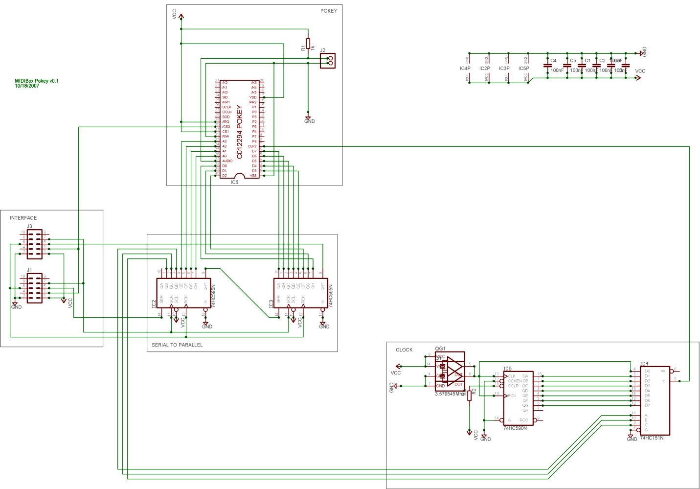
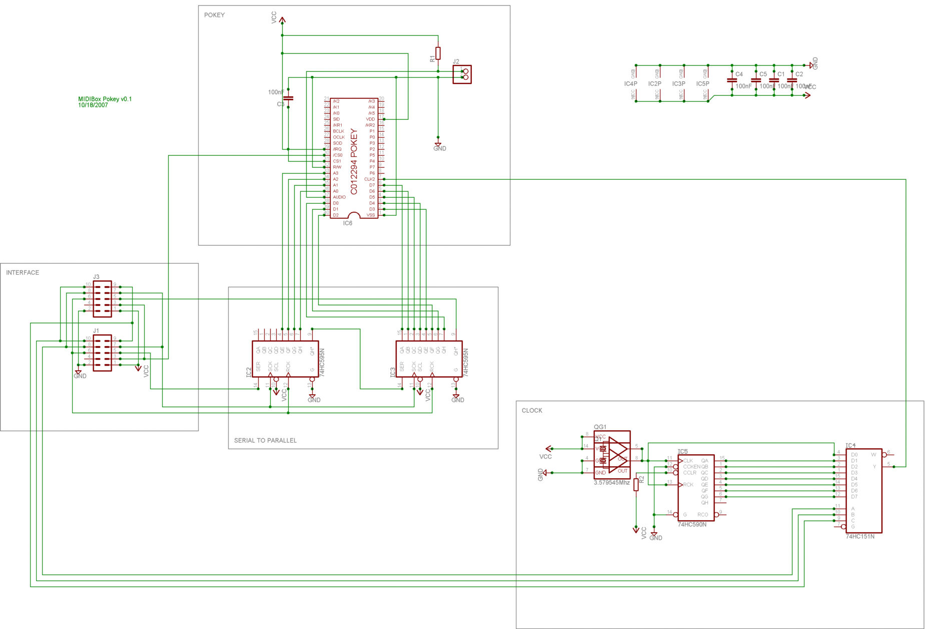
More updates! Thanks the the ingenious Mr. Jimp support for software octave switching is now included as well. Hooray. New revision of the schematic is attached. Some minor flaws are fixed as well. The untested source code for Core -> Pokey communication is done as well. It compiles so I assume it's working just fine ;) Missing parts are ordered and will arrive here in a couple of days. This means I'll be sitting in a corner, crying out my eye-balls in about 5 days. This is what it looks like: void PokeySRWriteBit(unsigned char reg, unsigned char bit) { // bcf POKEY_SR_LAT_OUT, POKEY_SR_PIN_OUT ; set out pin depending on register content (reg.bit) LATDbits.LATD6 = 0; // btfsc reg, bit if (reg & (1 << bit) == 1) // bsf POKEY_SR_LAT_OUT, POKEY_SR_PIN_OUT LATDbits.LATD6 = 1; // bsf POKEY_SR_LAT_SCLK, POKEY_SR_PIN_SCLK ; rising clock edge LATDbits.LATD5 = 1; // bcf POKEY_SR_LAT_SCLK, POKEY_SR_PIN_SCLK ; falling clock edge LATDbits.LATD5 = 0; } void PokeyWriteSR(unsigned char addr, unsigned char byte) { // MIOS_PARAMETER2[7..0]: Data // MIOS_PARAMETER1[4..0]: Address // MIOS_PARAMETER1[5] : Reset // POKEY_SR_Write // clock divisor for the muxer has to be added to the address first :D addr = addr + clock_base << 4; // bcf POKEY_SR_LAT_SCLK, POKEY_SR_PIN_SCLK ; clear clock LATDbits.LATD5 = 0; // POKEY_SR_WRITE_BIT MACRO reg, bit PokeySRWriteBit(byte, 0); PokeySRWriteBit(byte, 1); PokeySRWriteBit(byte, 2); PokeySRWriteBit(byte, 3); PokeySRWriteBit(byte, 4); PokeySRWriteBit(byte, 5); PokeySRWriteBit(byte, 6); PokeySRWriteBit(byte, 7); PokeySRWriteBit(addr, 0); PokeySRWriteBit(addr, 1); PokeySRWriteBit(addr, 2); PokeySRWriteBit(addr, 3); PokeySRWriteBit(addr, 4); PokeySRWriteBit(addr, 5); PokeySRWriteBit(addr, 6); PokeySRWriteBit(addr, 7); // bsf POKEY_SR_LAT_RCLK, POKEY_SR_PIN_RCLK ; latch POKEY values LATCbits.LATC4 = 1; // bcf POKEY_SR_LAT_OUT, POKEY_SR_PIN_OUT ; clear out pin (standby) LATDbits.LATD6 = 0; // bcf POKEY_SR_LAT_RCLK, POKEY_SR_PIN_RCLK ; release latch LATCbits.LATC4 = 0; } // PokeySRWrite[/code] Edit: Code change - I missed the 3 lines on SR1 for the muxer...

-
my midibox sid freeze on startup when the din modules are connected
nILS replied to ALCOLOIC's topic in MIDIbox SID
crashes on startup != fully working :D I had the problem with the DINs once. I had plugged the cable from the core to the DIN in the wrong way around... I'm pretty sure you checked that already though... -
zxautumxz, please don't get this wrong: You are absolutely welcome here. We are thankful for and happy about everyone joining the community. BUT: Your question have been answered. 5 times to be exact. I answered it about a week ago, with the only possible answer: go read. You have obviously not done any reading so far, or you'd know where "that sid on youtube in the c64 case" comes from. This is a DIY project, which means YOU need to DO something. The first thing you should do right now is to directly go to http://www.ucapps.de and start reading. Don't stop until you've read every single page that is connected to the sid in any. This should probably bring up some more questions, which we'll be happy to answer. It's just really hard and pointless to answer questions like "I want one. What now?". So now - go read up :D
-
PacTec PT-10 Bulk order for Europe, (case for MB-6582). CLOSED
nILS replied to TheAncientOne's topic in Bulk Orders
BTW, for the germans: JB Weld is avaiable at all OBI and TOOM stores. -
Okay, this is the hopefully final schematic for the mbPokey board. I'd greatly appreciate if some of you could help me double check it :D What's new: - added a 74HC151 do allow for software-triggered clock switching (might be removed again if it does not yield nice results) - added serial out to allow for multiple pokeys EDIT: Parts lists name value descr. package C1 - C6 100nF ceramic cap 5.08mm IC2, IC3 74HC595 shift register DIL16 IC4 74HC151 muxer DIL16 IC5 74HC590 binary counter DIL16 IC1 C012294B-01 AMI Pokey Chip DIL40 J1 pin header core connection 2x5 J2 pin header audio out 1x2 J3 pin header slave connection 2x5 Q1 3.579545Mhz crystal oscillator DIL14/DIL8 R1 1k Ohm resistor 0207/2V R2 10k Ohm resistor 0207/2V[/code] IC sockets (4xDIL16, 1xDIL40) not listed.
-
By saying "basically any frequency" I was talking about anything *below* 1.8432 Mhz. I don't a huge variety of oscillators here so I couldn't really test a lot above that. Using the 3.57Mhz from the oscillator I use atm directly did not work. I'm using a binray counter to divide the frequency thus my choices of Fin are 3.57, 3.57/2 = 1.79, 3.57/4 = 0.89 (...). These all work and they do nicely as dividing the Fin by 2^n leads to Fout jumping in octaves. Pitch is not that big a problem anymore, so I tend to stay within a reasonable range of the Fin intended for the pokey. Exactly right. Partially true. It greatly depends on the part of the scale you're in. If you move towards the high notes in the range of playable notes (determined by Fin) the needed AUDF values move a lot closer together leaving you with less steps for pitch bending.
-
Some updates on the progress: After receiving the nicely packed parts from SmashTV (thanks again!) I did some more research and fiddling. Amazingly, the POKEY works on basically any input frequency. So the frequency divider I put on the board basically works as an octave shifter atm :D Even with the "correct" oscialltor/frequency I notice some glitches. These might be related to the PC's parallel port or the way the driver acts on Windows XP. I've obtained a copy of Windows 98 to find that out. Right now. Actually.
-
Where can i buy SMD MIDI female connectors?
nILS replied to dontplaymygame's topic in Parts Questions
Three layers of bubble rolls. Plus at least 3 sealed anti-static bags :D Getting a parcel from smash is way better than christmas! -
Since I figured that you'd have very limited space under the button pads using the 5x7 seemed like a good idea cause they are pretty compact. Some more research brought this up: http://www.lc-led.com/Catalog/department/35/category/48 Might work for you.
-
Looks good to me :D
-
If I read you message correctly, you want 4x4 velocity sensitive buttons with transparent caps and some sort of display under each button that tells you what this pad's function is atm. Is this correct? If so I'd go with LEDs of some sort. - If you have 8x8 leds you could display tiny icons or letters under the pads. You could use those nice little dot matrix displays as well - 7 Segment displays will get you numbers and some letters - Alphanumeric displays will get you numbers and letters
-
Before you buy your kits, you might want to do a lot of reading at ucapps.de. And you should decide some things for yourself: 1) Do you want to build an mbSID v1 or v2? 2) Do you want just a single SID with no control surface, do you want the minimal control surface or do you want the full control surface and possibly more SIDs?
-
BankStick X2 ready to etch, can anyone verify the layout?
nILS replied to sineSurfer's topic in Testing/Troubleshooting
jimp, after our "discussion" about the mini-tiny-pokey board, I actually tested double-sided component stuffing with overlapping ICs. It's not fun to solder, but it works :D -
BankStick X2 ready to etch, can anyone verify the layout?
nILS replied to sineSurfer's topic in Testing/Troubleshooting
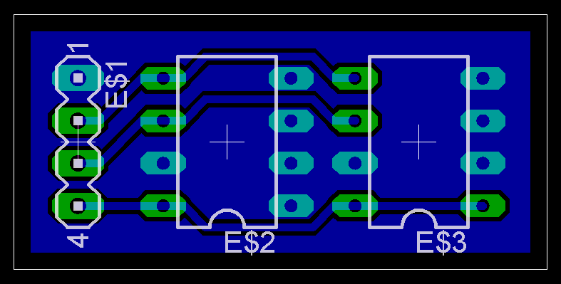
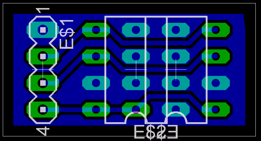
The only reason I could come up with for wanting a Bankstick board with less than the maximum amount of memory would be size - so, I'd try to get the board a bit more compact if I were you :D BTW, there IS an error in the board. Both ICs have all address pins dragged to ground. See http://ucapps.de/mbhp_bankstick.html to fix this. I added a layout I just threw together, toi give you an idea about how to minimize size a bit. The second picture has the right IC mounted to the other side of the board, reducing size even further :D These layouts do not have mounting holes in them yet. I merely posted them to give you an idea of what I think you should go for.

-
There you go: www.schickt.de/temp/pokey_test.mp3 Not really anything to drool about though. I've recorded this using the "wrong" oscillator which messes with the pokey quite a bit. It's just some random test notes. As soon as the parts from Smash get here I'll try to put something more interesting together. If anyone doesn't know what the Pokey sounds like at all, I have an mp3 with some tunes from Raster tracker: http://www.schickt.de/pokey/pokey.mp3 (lousy quality)
-
idiotcountry2: I heard and read a bit about that, and will surely check it out in more detail. Thanks for the hints!
-
Me, too :D
-
Once again, TK steps in, corrects my mistakes and saves the day :D
-
Within 2 seconds after power up MIOS should send an upload request. You don't happen do have an LCD handy, do you?
-
Exactly :D
-
If you measured all the voltages as described on ucapps you should be fine. Just check some other pins to see that there's NO voltage there =) I assume you got the PIC pre-programmed? I have a simple optocoupler-test board here, which I made according to some schematic about 3 years ago, so there IS some info on it somewhere around here - I just don't know where anymore. A little searching should give you the results you need though. EDIT: Found it: http://www.ucapps.de/howto_debug_midi.html. There is a simple schematic to test the opto and an in-circuit one as well.
-
What I think really helps reduce the amount of cables is to have a combined frontpanel-din-dout-pcb. A lot of layouting to do, but you'll only have 9 lines going from the master core to the CS-pcb. I saw an interesting idea around the forum, that I have been toying with as well. Instead of having those 4 sections (OSC, ENV, LFO, FILTER) which are all fairly similar, you could just make one section with the maximum amount of buttons/encoders needed for each section and add a selection button + 4 LEDs. Basically the max. amount for each section is: 5 encoders (OSC + ENV) + Button and 3 LEDs for selection of enc function 1 Button + 6 Select LEDs (LFO) 1 Button + 5 LEDs (LFO -> Waveform) 1 Button + 2 LEDs (OSC) Doing this would reduce the amount of encs/buttons/leds on the front panel to about a third.