

Wilba
-
Posts
3,310 -
Joined
-
Last visited
-
Days Won
2
Content Type
Profiles
Forums
Blogs
Gallery
Posts posted by Wilba
-
-
Awesome!
*glug*
-
They will work too. They probably use the "default" encoder pinout, not the "alternative" ALPS STEC16B pinout as seen in MIDIbox wiring diagrams.
-
TK used ALPS STEC16B a long time ago... so this exact model has been used in MIDIboxes for a long time. The same design has been made by other manufacturers... e.g ECC (available via Voti.nl) and Soundwell (available through bulk orders from me). I was selling the Soundwell ones wholesale in MB-SEQ/MB-6582 parts kits and then using them in sammichSID kits (until they ran out).
Now Bourns make them (or at least they are new to Mouser), and are FAR cheaper than the Alpha brand I'm currently buying for sammichSID kits.
AFAIK this one (Mouser p/n 652-PEC16-4220FN0024) is the exact same design as I've used and made available... it's a good size for using 10mm gap between PCB and a 1.5mm-3mm panel. This doesn't have a switch.
Mouser p/n 652-PEC16-4220FS0024 is the same design but with a switch.
Note that I haven't actually got samples of these yet, but I'm pretty confident they're exactly the same as the ones I've been using in my control surface designs, therefore I'm going to buy 50 for the last batch of sammichSID kits.
As for connecting to a DIN pin... I haven't connected my last revision of MB-SEQ PCB (with support for encoders with switches) to a Core32 and configured MB-SEQ V4 to use the switches. Maybe someone else has and can comment. What you should do, though, is wire all those switches in parallel and connect them to a single DIN pin. It doesn't really matter which DIN pin, because you can configure that in the DIN table. There is already a "FAST" button on the standard control surface, but I don't think you'd want the encoder switches to be the same as this button... maybe instead you only want a temporary "fast" function which increases the speed only while the encoder switch is pressed... that might require a bit of coding somewhere if TK hasn't implemented that feature (though he typically does implement cool features like this if you ask nicely!)
-
btw this was just an amusing diversion from packing sammichSID kits... if you don't want to use the logo I won't be offended.
also, just noticed the blind threaded mount holes... nice...
-
I exported to .hpgl (not .plt) from Inkscape... imported into FPD. This is using the original three-stroke vector engrave artwork used on acrylic.
I couldn't get Inkscape DXF output into a CAD package... I don't know what went wrong. But I do agree with nILS... the best way to get vector art into FPD is by using a CAD package and "plotting" to an HPGL file... that's how I usually do the optimized versions of my FPD panels (MB-6582, MB-SEQ).
If you want, I can get the labels to match the original sammichSID panels.
-
What am I supposed to do? Someone please remind me...
-
I'm sure there's some way we could convert the sammichSID logo into an HPGL file and import into Front Panel Designer...
-
-
This might be easier to work with than the SVG...
-
Great score!
I want to build something that has a LCD display, easy controls, stored instrument settings, and all MIDI controllable. I get the impression that the MIDIBOX is my solution. While 1 SID chip would be enough, I wouldn't mind the full 8. Why limit myself when I have lots of these things?
If you want to use "the full 8", you might want to consider this: http://www.midibox.org/dokuwiki/wilba_mb_6582
You could build it "stock" or use just the base PCB and build your own control surface/case, perhaps in a C64 breadbox case, i.e. like what this guy did: http://www.subatomicglue.com/sidl0g/
Also, I strongly recommend hanging on to all your C64 PSUs until you test which ones work well in a MIDIbox SID with all 8 SIDs... 8 SIDs draw a lot of current, some C64 bricks don't handle it well, or are noisy (on the audio or buzzy transformers). You might as well pick the least noisy of the lot!
-
Woot :frantics:
-
I would suggest replacing the big 470uF cap... it might not be working and sufficiently smoothing the voltage after the bridge rectifier.
Oops. I assumed there WAS a bridge rectifier... looks like it's only a diode.
http://www.ucapps.de/mbhp/mbhp_sid_c64_psu.pdf
It is relying on AC->DC rectifying on the SID module, and the big 2200uF cap there.
I think this circuit is better:
http://www.ucapps.de/mbhp/mbhp_8xsid_c64_psu_optimized.pdf
I can't say this is going to fix your noise problem, but it might be easier to diagnose what is wrong. It's doing the opposite of the other circuit... it powers the 5V/ground of both modules with the already regulated 5V DC/ground... then the separate 9V AC from the C64 PSU is rectified/regulated into 9V DC, and this 9V DC is added to the 5V DC (note 7809 middle pin is connected to 5V, not ground like most PSU circuits, therefore it's output is going to be 9V higher relative to the middle pin).
Something to consider anyway. Try replacing the 470uF first.
-
Sorry, can't send bankers draft overseas... it will have to be via Western Union. :D
-
Du sprichst Deutsch ?
Nein.
-
I concur with TK, I've had this "every 2nd patch is crap" problem before with patch upload via SysEx dump when the delay was not high enough.
-
Der Ober zu einem Ostfriesen: "Ihr Glas ist leer, soll ich ihnen noch eins bringen?"
"Unsinn, was soll ich denn mit zwei leeren Gläsern?"
Und die Moral von der Geschicht: Hör auf nILS, den Klugscheisser.
-
LOL
BTW If you're not happy with the red LEDs in your kit, you can send them back for a full refund ($3).
-
sammichSID Final Batch!
After 350 kits sold (including 556 SIDs), I have finally got to the end of the waiting list. Woot!
There will be a final batch of 50 kits in November. I don't have plans to keep lots of pre-packed kits in stock, therefore, once the last batch is sold, YOU CANT HAZ SAMMICHSID! There are still plenty of kits available in the final batch.
Yes, this is some shameless self-promotion to boost sales so I can finish with my routine 50 kit batch and sell off all the PCBs and parts I have in stock.
If you're interested in getting a sammichSID, or want to find out WTF this thing is, all the information is here: http://www.midibox.org/dokuwiki/sammichsid
-
Also... you can get your 5V DC for testing from the sammichSID itself... use J2 in the bottom right corner on the base PCB, or even J2 on the control surface PCB (Vd=5V, Vs=ground).
-
The LEDs on sammichSID are multiplexed... they are in an 8x6 LED matrix, but driven by the PIC using the default MIDIbox SID 8x8 LED matrix code, so in reality they are really in a 1/8th duty cycle.
In my experience, if you are testing what resistor will work, testing one LED with constant 5V will be about the same brightness as when it is in the matrix, it won't be much less bright when put in the matrix. It depends on the LED type, though. But as a rule, it's OK to pick a resistor using constant 5V as a test.
Alternately, solder the LEDs before soldering the resistors, run the sammichSID CS test app (I really should put this somewhere better):
and then touch resistors in the pads to see actual brightness. You could in theory put all 8 resistors in the pads (without soldering) and trim/bend the leads to make good contact.
As a general rule, ultrabright LEDs (especially white or blue) will need at least 1K resistors... perhaps even as much as 3K.
-
It could be PSU related, but also, 6581 SIDs are notoriously noisy.
How exactly are you powering the SID module (i.e. circuit)? I'm assuming you are using an 78L12 voltage regulator on the module (for 6581 SIDs). What is the voltage going into the 78L12? and what voltage going out? (should be 12V). Test these on startup, when you are experiencing low volume... maybe you can observe the voltage being lower than expected.
Have you connected the audio in to ground on the SID module? This is a common cause of noise, if you're not using it, ground it!
If you haven't done that already, do that, and record new audio clips.
-
If I was still selling SIDs, the current price would be 260 AUD (~255 USD). It's also built by an old hand at soldering so it's a real bargain.
Did you paint the engraving yet?
-
Damn! Missed opportunity for a beer donation... oh well... buy nILS one instead.
 :thumbsup:
 -
A 30K pot won't help, since you're using the pot as a voltage divider, the range would still be 1.5V - 3.5V (assuming 0V-5V, 40% range at middle).... I'm guessing, you might have one that is only the starting 40% so the voltage is 0V - 2V.
Converting 40% of a 10 bit value into 7 bits would work, but you'd be bypassing the built-in jitter handling. It's much better to use 0V-5V inputs into the Core.
You could try shifting and amplifying the voltage, but that would involve opamps. I'm not the best person to explain how that would be done... but in theory you could do it with a rail-to-rail opamp... assuming the middle of the range is 2.5V, it could amplify 1.5V-3.5V to 0V-5V.
You could also try modifying the pot so the full range of resistance is only in the middle 40%. That would involve opening the pot and "shorting" the resistant strip at each end... you could use a silver conductive pen (eg. this: http://www.amazon.com/CircuitWriterTM-Precision-Pen-silver-based-grams/dp/B0002BBVQO ). You would have to carefully measure the pot's resistance at the ends of the modwheel's range, then with a multimeter, work out where that corresponds on the resistant strip, and "paint" from those points to the ends of the strip. Again I'm assuming it's the middle 40%, if it's only the starting 40%, you only need to paint one end.
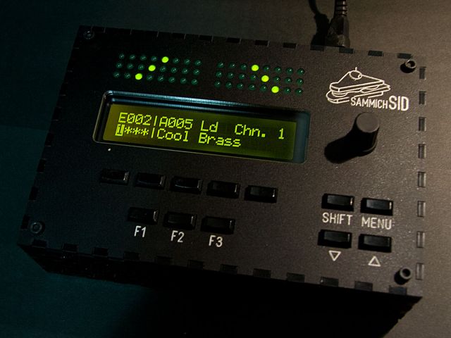
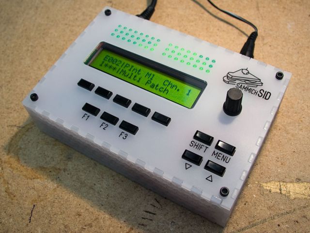
sammichSID Prototype
in Design Concepts
Posted
lol
I'll trade a built sammichSID with SIDs for a Slim Phatty.
Just sayin...