Wilba
-
Posts
3,310 -
Joined
-
Last visited
-
Days Won
2
Content Type
Profiles
Forums
Blogs
Gallery
Everything posted by Wilba
-
Great design! It has an 80's retro feel :)
-
There is a DXF for the panel, but I am not sure how well the PCB would mount to acrylic... it's something I'm interested in though. The design relies on "studs" on the back of the panel. If you get a panel from Schaeffer/FPE, you can get them to make threaded holes on the back (that you don't see on the front). Then additional 10mm spacers are glued to the back for more support for the PCB. I don't think threaded holes is possible with acrylic (especially laser cut only). Perhaps countersunk screws through the panel, on left and right sides and more for the LCDs, might be enough... and/or plastic spacers glued in the middle. I do not recommend screws through the middle of the panel, there is little clearance. Ponoko is also a good option for a laser cut acrylic panel, they have a lot of materials in 3mm (even wood!), the only limitation is how to mount the PCB. If someone knows how to glue nylon to acrylic, that would be really cool :-)
-
Read the SID V2 User Manual about Ensembles.
-
When you put multiple 24LC512 (or 24LC256) on the same "chain", pins 4-8 will be the same on both (like you have in this picture)... but E0/E1/E2 must be different, they give that IC it's "ID". Here's a clearer schematic: http://www.ucapps.de/mbhp/mbhp_multi_bankstick.pdf It's simplified a bit... you would connect up the 5V and ground pins also... this means you can join many pins of one IC together and then just connect each IC to a common wire. You can remove any of the ICs in this schematic.... ie. you can have just two, one with ID=0 and one with ID=7 (for MB-SID this is good, ID=7 is used for the "ensemble" storage, ID=0 to ID=6 is for patches).
-
OK... when you said "PIN 11" you also said "(D2)"... and I was counting pins from the MB-6582 PCB labels, which increment left side then right. However, your pin counting is common, as it also matches order of wires in a ribbon cable/IDC connector. So look at the Core schematic just one more time to confirm that you refer to pin "D2". Note that MB-6582 PCB J15_CORE1 matches J15 in this schematic (i.e. it is in the same position next to the PIC) but some pins should not be connected! Look closely at the PCB drawing at J15_CORE1: http://www.mb6582.org/plans/MB-6582_Base_PCB_R2_Color.pdf The tracks leading away from D0, D1, D2, D3 (according to same pin numbering, pins 9,11,13,15) go through a "solderable jumper" on the bottom of the PCB (it looks like two rectangles with a small gap between them). These are in case your LCD does not work with 4-bit mode and you need to use 8-bit mode. So normally you do not solder them or short them with wire etc. you just leave them alone. For you to get any voltage on D2 (with no LCD connected) is a fault - because it should not be connected to anything on the PCB. The same applies for all four pins D0, D1, D2, D3. I will let you check this and help you more afterwards.
-
This sounds like a voltage regulator problem perhaps... or the C64 PSU is faulty. You say you are using PSU Option B... did you check the bridges are correct for J71, J72 and J73? Please explain what "PIN 11 (D2)" means. Try one thing now (to help diagnose the problem): Take out all the jumpers in J1_SID1, J2_SID1, J1_SID2, J2_SID2, etc. the ones that select which voltage that SID will use (9V or 12V). With these taken out, the SID module should not have a 9V/12V supply so if there is still hum on the audio outputs, that's VERY strange, if there is no hum, then we've isolated it to a problem with the voltage outputs (or at least can check them next). What can happen is, if the 5V supply of the C64 PSU is faulty, then for PSU Option B, so will the 9V/12V supply, because the inputs for V2 and V3 are the SUM of the 9V regulator V1 and the regulated 5V supply from the C64 PSU.
-
I was wondering when you'd ask :)
-
It is now stretched to 31. Unless you're a regular customer of mine :) you may have to wait for another batch of PCBs.
-
I have 25 (unconfirmed) orders already. I've sent emails to those on the list. I may stretch it to 30 if there's a few more people interested (pref. people who have encoders already, I won't have enough for everybody). Deadline will be 1st July, when I hope everyone who has confirmed will have paid for the PCB production (I will sell PCBs for US$25 each). More pollution then: Here are some close-up photos during construction... I don't think I showed these before. http://www.mb6582.org/temp/IMG_2398.jpg http://www.mb6582.org/temp/IMG_2399.jpg http://www.mb6582.org/temp/IMG_2400.jpg http://www.mb6582.org/temp/IMG_2402.jpg
-
That's for PLCC ICs, not DIP ICs. You want the el cheapo one. http://parts.digikey.com/1/parts/303249-ic-extractor-tool-t90.html You can probably find it cheaper than Digikey, but this one is lucky yellow like mine.
-
i need a circuit diagram 4 this
-
Getting both a solder sucker and some desoldering braid is a good idea, as they each have their uses. For example, sometimes the solder sucker will suck out most of the solder from a joint, but some might be left in the hole, then the braid can be used to get that last bit out. For a very small pad, sometimes it's safer to use just the braid and not accidentally suck up the pad with the sucker.
-
Adding instead of replacing lets you short it out if you change your LCD and go back to just R4 of 1K. It also means you don't have to desolder the resistor and potentially damage the pads. But you are right, 47K or 48K won't have much difference.
-
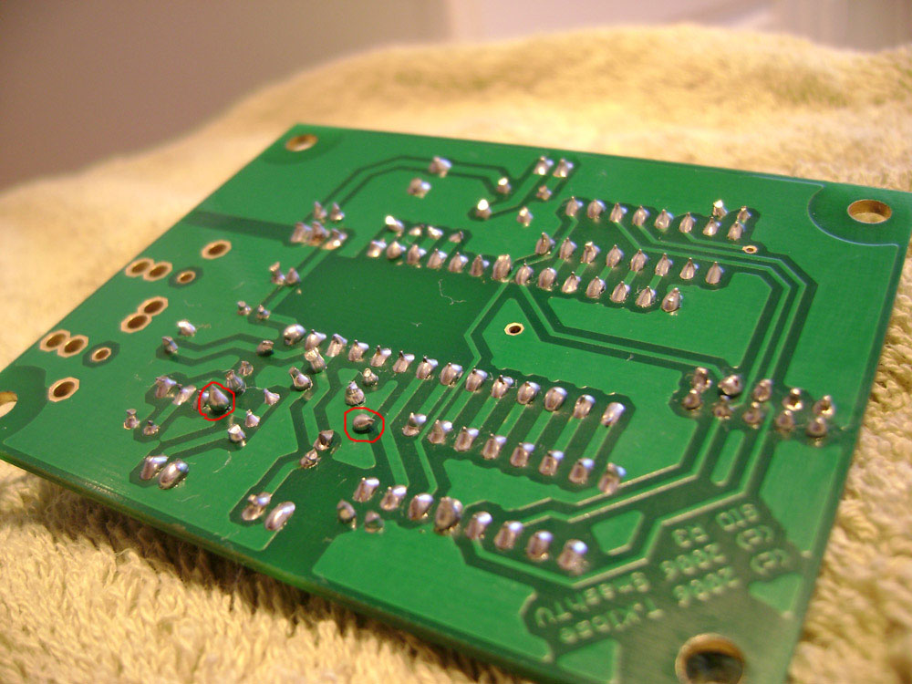
You're using too much solder. You should try heating the joint first, then applying just enough solder so it gets sucked into the hole, then add a tiny bit more to get a nice "tent". What might be happening is, you're heating up the lead/pin enough for solder to stick, but not heating it up enough (or for long enough) so the solder gets sucked into the hole. Sometimes you might have trouble with long leads or a pad on the ground plane (see pic). These you should do again... it hasn't formed a good joint onto the pad.
-
-
That makes no sense. SmashTV sells the same IDC connectors for 50c each, and one meter of ribbon cable for $2. How does that make Sparkfun's one 6" cable "pretty cheap compared to Smash's stuffs." ?
-
Note, do not REPLACE, you ADD this 47K resistor.
-
Plans are now available: http://www.midibox.org/dokuwiki/wilba_mb_seq Note the PCB has changed to be one piece! In the next few days, I'll get quotes on the revised PCB and based on interest, run a mini-bulk order for the PCBs (about 20) and some parts like knobs (I have plenty of those now, thanks nebula!), switches/caps, bicolor LEDs and maybe the resistor networks. I may have enough spare Soundwell encoders at the moment to share with 10 people, the rest will have to buy from Mouser, Voti, or beg on the forum for people to share their bulk order stashes. I always intended ordering another 2000 encoders for the bigger bulk order, but that isn't happening before or during this mini-bulk order. These 20 or so would be people who are either making or buying their own panels (i.e. through FPE/Schaeffer) and doing a fully DIY case, NOT people waiting for a case from Doug. In case I miss your name in this thread, or some conversation we had once in PM or chat, please remind me about joining the mini-bulk order by email. If you want to join the mini-bulk order, just email me: Jason.S.Williams@gmail.com
-
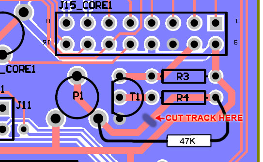
OK, I have this exact model (with low-power amber LED backlight). See page 3. Only the "yellow-green" LED backlight model has a current draw of around 280mA, all the others only have a single LED on the side and draw much less, 20-25mA. Therefore it's likely you are supplying this LED with too much current. Luckily, these models are quite easy to replace the LED, if you have to. To reduce the current supplied by the Core backlight circuit (in this case MB-6582), insert a 47K resistor in series with R4 (either between R4 and T1 or between R4 and P1). See attachment.
-
Post a link to where you got the LCD, or a datasheet, etc. It's possible it's an edge-lit backlight and needs much less current than what the Core module provides.
-
Tips for cutting ventilation slots in a PAC-10 case?
Wilba replied to fussylizard's topic in MIDIbox SID
Awesome job! Much better than my hand-carved effort... :-) -
SmashTV says those Xicon capacitors may be rated to 16V but can handle much higher. It was his decision to supply 16V rated 2200uF capacitors based on knowing more than I do about these things, i.e. they work, they won't explode, so stop worrying :P
-
yes, same place...
-
Can you upload the datasheet for this Optrex LCD? It's white LED backlight, sometimes (a lot of the time) these are edge-lit and use only a few LEDs, not a whole array. Thus they only need 25mA-40mA current and not 280mA+ like a typical yellow-green LED array LCD. It's possible you burned out the white LEDs. If you want to use a low-power LED backlight, you need to add a resistor in series with R4 so that the current is limited. A good safe value is 47K, which will limit current to approx. 25mA or less.
-
There is no waiting list. If you were on the waiting list, you have a PM. All orders to be emailed directly to me ASAP.