Wilba
-
Posts
3,310 -
Joined
-
Last visited
-
Days Won
2
Content Type
Profiles
Forums
Blogs
Gallery
Everything posted by Wilba
-
With my suggested wiring of feedback pots for MB-6582, you don't need a switch, unless you want to add audio in jacks.
-
IMHO this is his best project ever.
-
SIDv2, MB6582, SSM2044, AOUT_NG Praise and a couple questions.
Wilba replied to lukas412's topic in MIDIbox SID
It's J11_COREx. It aligns with PIC pins, so left pin is TX, right pin is RX. You can cut the RX track on the bottom layer track between the pin and the via. Convenience! Yeah something like that is on my todo list... I need to box my SSM filters in something other than a shoebox :) -
Yeah 1K is really limiting the current (you can do the math)... but its a fairly safe to use for any LED, since at most it's I=3 Volts/1000 Ohm = 3mA. Believe it or not, that is a good value for the red LEDs that SmashTV sells, even when used in an 8 column LED matrix! Most of the time, a 220 Ohm resistor will work well and keep the current under the typical maximum (I=3/220=13mA) 150 Ohm in this case is pushing the LED to the limit, and might even be too bright for this context - remember you're staring at these switches all the time. Note also that all that current adds up... if you have 10 LEDs all drawing 20mA that's 200mA on top of LCD backlight, SIDs, etc. Try 1K first, if it's too dim, try 560 Ohm (or use two 1K in parallel to make 500 Ohm), still too dim, try 220 Ohm.
-
SIDv2, MB6582, SSM2044, AOUT_NG Praise and a couple questions.
Wilba replied to lukas412's topic in MIDIbox SID
btw are you connecting the MB-6582 to AOUT_NG via the expansion port? Maybe there are spare pins for this extra MIDI channel... female 5-pin DIN plugs are easily available. -
SIDv2, MB6582, SSM2044, AOUT_NG Praise and a couple questions.
Wilba replied to lukas412's topic in MIDIbox SID
I agree, sounds like the brick is sagging under load. You could try removing SIDs and see if the problem happens less often, that would prove it's a current load problem. That's certainly possible. Perhaps you don't need an IIC module. All the PICs share a common MIDI In (i.e. RX pin of PIC) but you could cut the track to the 4th PIC. The TX and RX pins are available as a 2-pin header, so if you want to reconnect it as per the MB-6582 PCB, you just connect the RX pins again with wire. Then just put the same MIDI In/Out circuit as you'd find on a Core PCB - i.e. the optocoupler and 220 Ohm resistors... these could fit behind whatever MIDI sockets you use, so you only need 5V/TX/RX/Gnd connected to the 4th PIC. While the CAN bus between all the PICs would still be connected, I don't think that would be a problem if CAN is not being used by the app... but it's probably best to only use PIC18F4685 in that socket since there's a diode bridging pins which are used for LCD output in other PIC types. -
The resistor can go on the anode (+) or cathode (-) side, it's limiting the current through both the LED and the resistor. Great reference site: http://www.kpsec.freeuk.com/components/led.htm You'll need to check the current limit on the LED, then use Ohm's Law to calculate the required resistor for the voltage. Most LEDs typically will work under their limit (25mA typically) with a 5V supply and 1K resistor. You might use a lower value resistor for more current, but check the specifications and don't push it to the limit, it's better to use a slightly bigger resistor and not burn out your LEDs.
-
I guessed this URL: http://www.ucapps.de/mbhp/mbhp_multi_bankstick.pdf from the image URL: http://www.ucapps.de/mbhp/mbhp_multi_bankstick.gif
-
Sweet! Can the same performance work the other way? i.e. software sequencers controlling (STM32-based) hardware synths via a virtual MIDI interface across USB?
-
joewhat: what is that case? It looks really interesting.
-
Yes, I agree! I removed the bankstick in ID=7, and I can't save in Ensemble #1, which I believe should be possible. I also observe on the Ensemble page, "Ensemble: E001*"... I have no idea what the "*" means. So basically, I can store and recall Ensemble #1 if there's a bankstick in ID=7, but if there is no bankstick in ID=7, it recalls what was saved in Ensemble #1, but I cannot save the ensemble (at least parameters such as MIDI channel and patch do not save). It is a bug which should be fixed, I agree, but I strongly recommend you get a 24LC512, put that in ID=0 (so you can store 128 patches instead of only 64) and then put the 24LC256 in ID=7 (you don't need the bigger 24LC512 for ensembles)... even with a dual-SID setup, being able to switch between properly configured ensembles for each of the engine modes (Lead, Bassline, Drum, Multi) is almost a required feature :)
-
Describe your setup some more. What "banksticks" do you have connected? i.e. part number and ID (address) they are on... patches are stored in ID=0 to 6, ensembles use ID=7. Did you upload using "feedback from core"? You can try reformatting the banksticks perhaps, or swapping them temporarily. i.e. put the ensemble bankstick in a patch bankstick socket, turn on, wait for it to "format", turn off, put it back in the ensemble bankstick socket, turn on.
-
Ahh... FTSN Negative... this is basically a green version of the red one I've used. Nice. Cheaper than Optrex STEP displays, almost as good. It's been fun watching you guys build and blog about it... I may have to send you some tinted grey 3mm acrylic windows to go between the panel and LCD... fills the gap nicely and you don't notice it anymore. Black sharpie on the panel cutout edge finishes the job nicely. You see people? Pics get rewards! P.S. 2000 posts :)
-
There is no address bus - patches are stored on 24LC512 serial eeprom. The fact that some are stored and others are not suggest the firmware is ignoring every 2nd one probably because it's too busy storing a patch.
-
What LCD are you using? Seems to have nice contrast (and I'm shopping around atm)...
-
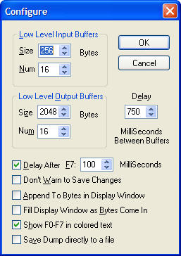
The bankstick upload problem is probably because you're uploading the .syx file and not delaying enough between each SysEx message. Try using MIDI-OX and changing the delay to 750 milliseconds.
-
Ooof! I forgot, that's what I do... but then I add more after. Always add more to cover the whole screw head and the panel, even if it means you need to "countersink" the PT-10 mount holes to accommodate a cone of JB-Weld around the screw head. The spacers stay stuck extremely well, the screws don't stick as well, as many people discover... :( I've never suggested this before, but once everything is assembled, you could permanently attach the panel to the PT-10 using some extra glue, that would stop the screws being stressed if you continually open and close the case (like I do).
-
Once I've cleared my queue of things to do/sell ;) I will run a small bulk order of the PCBs. I may have some parts to go with them, like encoders and knobs. The problem though is even I have not put mine in a case, made by Doug or anyone else, so I do not really know whether it is going to work as designed - i.e. to fit in a "desktop" case with 3U frontpanel that can be rack mounted if desired, or to fit in an off-the-shelf 3U rack enclosure. I mean I've checked the dimensions but there's very little clearance between the PCB edge and the inner faces of a case, and also (more important) not much clearance between the back of the panel and PCB components (especially the ICs on the right edge). I believe Doug is still planning to make a case, but I also agree that people may want to use this PCB and make their own case, so I will make the FPD (and/or DXF) files available to people interested in doing this. Just contact me by PM, including your email address and we can talk about your plans.
-
You can see what it should be by looking at the "Wav" parameter in the Oscillator page. It should cycle Off, Tri, Saw, T+S, Pul, P+T, P+S, PST, Noi.
-
Sounds like you have multiple problems. #1. You think you can't have multiple waveforms selected for SID oscillators. You can! This sounds better with 8580R5/6582 SIDs. MB-SID stops you mixing with noise waveform because this makes the SID oscillator stop working or something. #2. You think there is a sine waveform. Perhaps you are confusing it with triangle. #3. One or more waveform LEDs does not work (perhaps this is triangle?). First try testing if all the LEDs work. I uploaded mb6582_led_matrix_test2.zip in this post: http://www.midibox.org/forum/index.php/topic,10390.msg78577.html#msg78577 I really should put it somewhere more useful, like in the wiki :) Or, someone who actually used it should update the wiki for me. BTW photos of your finished MB-6582 would be nice :)
-
A toothpick or bamboo skewer works well... even if the blobs are a bit messy to start with, they clump together into nice blobs after a few minutes.
-
Nice! Me likey! "screw it up onto the panel" is probably the best way to describe it, never thought of using those words though... :) However, since the panel should probably be at the bottom, perhaps "screw it down" is better. By putting a nut between the screw head and the PCB, you can pull the screw up and turn it, using friction between the nut and PCB to gradually lower it into the JB-Weld blob, and the nut also holds it in place. A nut on the other side can hold the screw head off the panel while you prepare the JB-Weld blob, e.g.
-
[ x ] POIDH
-
offsite documentation....... <broken record>
-
Please clarify some things... Core 1 and Core 2 work OK? Core 3 left SID works OK? Core 3 right SID, testtone with SID makes no sound? Core 3 right SID, testtone with pin 8/27 bridge makes "quiet triangle wave"? (Is this sound different to testtone with pin 8/27 bridge in other Core/SID modules? It should be 1kHz square wave, not triangle.) A different sound from the audio out buffer (different to others) suggests the audio out buffer is not working. Check for bad joints, correct components, etc. in this area. You could also try testtone with a bridge of pin 8 from the left SID (which you say works) to pin 27 of the right SID (which you say does not work).... and vice versa. This would identify if the track between the PIC and pin 8 is working or not.