freddy
-
Posts
162 -
Joined
-
Last visited
-
Days Won
2
Content Type
Profiles
Forums
Blogs
Gallery
Everything posted by freddy
-
Nope, you see 'MIOS32' firmware (though might be worth updating in the SEQ4 page to avoid confusion, it still says 'Precompiled firmware for STM32F103RE') :-) In the midibox_seq_v4_054.zip file both core type binaries as well as source files are available. As for the core module itself, I remember TK saying 'use the STM32 if possible for old projects to help SmashTV's stocks disappear', not sure if it's still applicable though. Hth, freddy
-
Ah, sorry, refreshing the blog regularly but I missed the last post from Nov 7th ;-) I soldered two during the last day, I had no issues, was finished in 2 hrs and it worked right after the power-of, I only had slight issues while getting familiar to LPCXpresso, but I succeeded there as well... Can't wait to have it finished :-) I started soldering diodes yesternight, can't really decide if I should solder by sections or by components size. If I get some silicone glue it'd be better to solder by sections but since I don't have the glue yet holding the small components while soldering them might prove a bit difficult, I'd say... Nevertheless, I'll figure it out somehow :-) Good luck with the PCBs!
-
Hey, pcbatterij, anything new on this topic? I'm just about to start soldering 9090 boards tonight and this one looks quite interesting. Any progress on the sequencer prototype built? :-) Looking forward!
-
nILS, by lacking free pins I need to employ DOUT to interface digipot chips using SPI interface, this makes 2 wires + /CS signal. The code doesn't really work as expected so I need to hook my logic analyzer to the bus. The "logic analyzer" is built from LPT port (I had trouble to find it these days :rolleyes:) and therefore .1us (or similiar) delays are not really seeable by the LPT (I only got some 800kHz sampling rate). I'm using MIOS_DOUT_PinSet0/1 routines to set the SRIO value (so it takes definitely more time than .1us) but I still can't see the toggling signal, so I need to insert some delays in order to be able to monitor the SPI and debug further. But inserting MIOS_Delay of 1ms is too much since there are tons of bits and then the MIOS is really slow and busy spending time in delay loops. That's the point, once the code is tuned and verified I'll probably abandon the delays if the digipot chips are able to react (the CLK rate must be at least 20ns according to the datasheet so it should be no problem). Does the 1ms SRIO mode refresh time mean that I can't really toggle DOUT pins faster than in 1ms interval?!
-
This is not direct port setting but using SRIO, so I suppose the time will vary in my case. But knowing that NOP will take 1/10th of usec definitely helps. Thanks again.
-
nILS, yeah, dirty, but works. It's supposed to be a real delay so I don't really care about ineffectiveness of the code and see no reason to mess with interrupts for this. I'll make a label with a counter allowing me to set different delays. Thanks for the hint! :rolleyes:
-
Hello, during programming of digipot chips connected to DOUT pins I have the need to trigger CLK signal for a particular time. Calling 1ms MIOS_Delay is much too long (updating 16 digitpots with 6 registers each with 11 bit words just takes much too long), using no delay at all (i.e. triggering the pin to 1 followed by 0) is much too fast for my logic analyzer. How to achieve e.g. 1us delay (doesn't need much too precise, +/- 100ns is more than enough)? I cannot imagime how this might work with timer and within an interrupt-serve routine. I've tried to look through forums but couldn't find anything that might help me. Thanks, freddy
-
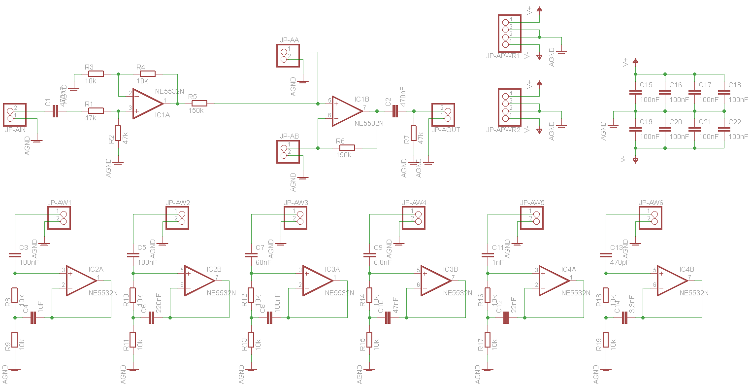
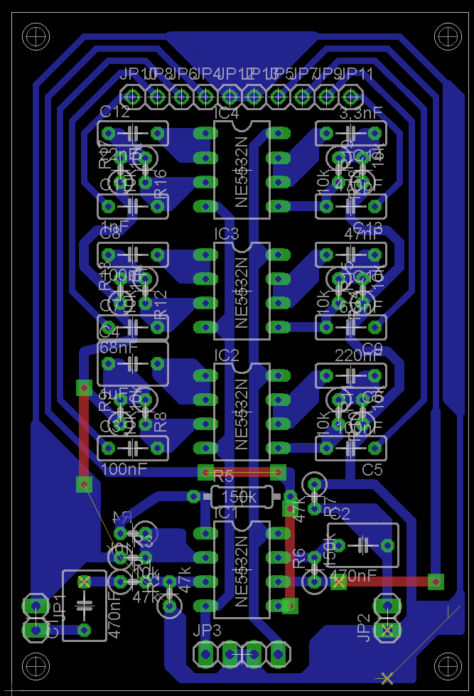
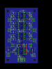
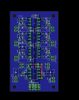
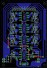
Tried it today, but whatever I do the output still looks the same. Regardless of which PCB design I use there is always 400kHz sine wave generated on inverting pin of IC1 (see attached schematics). The 400kHz frequency is determined by the oscilloscope. The sine wave and it's frequency stays the same regardless of input signal frequency and shape (using function generator, 50Hz-20kHz input wave, sine, triangle or square). This "noise wave" is then mixed into output, obviously, and causing noise as shown on previous photos. Since the frequency stays the same regardless what I do I'd expect it to be some "environment" noise or error (though of unknown origin). I ran out of 100nF filter caps at the moment, so I'll finish building the gyrators later this week. Meanwhile I'll solder one AD5206 and depending ICs and start modifying MBMixer code to work with AD5206. If anyone op-amp skilled looks at the schematics and an obvious reason for the noise occurs to him, please let me know as well :rolleyes: The up-to-date EQ PCB design is attached for reference as well.
-
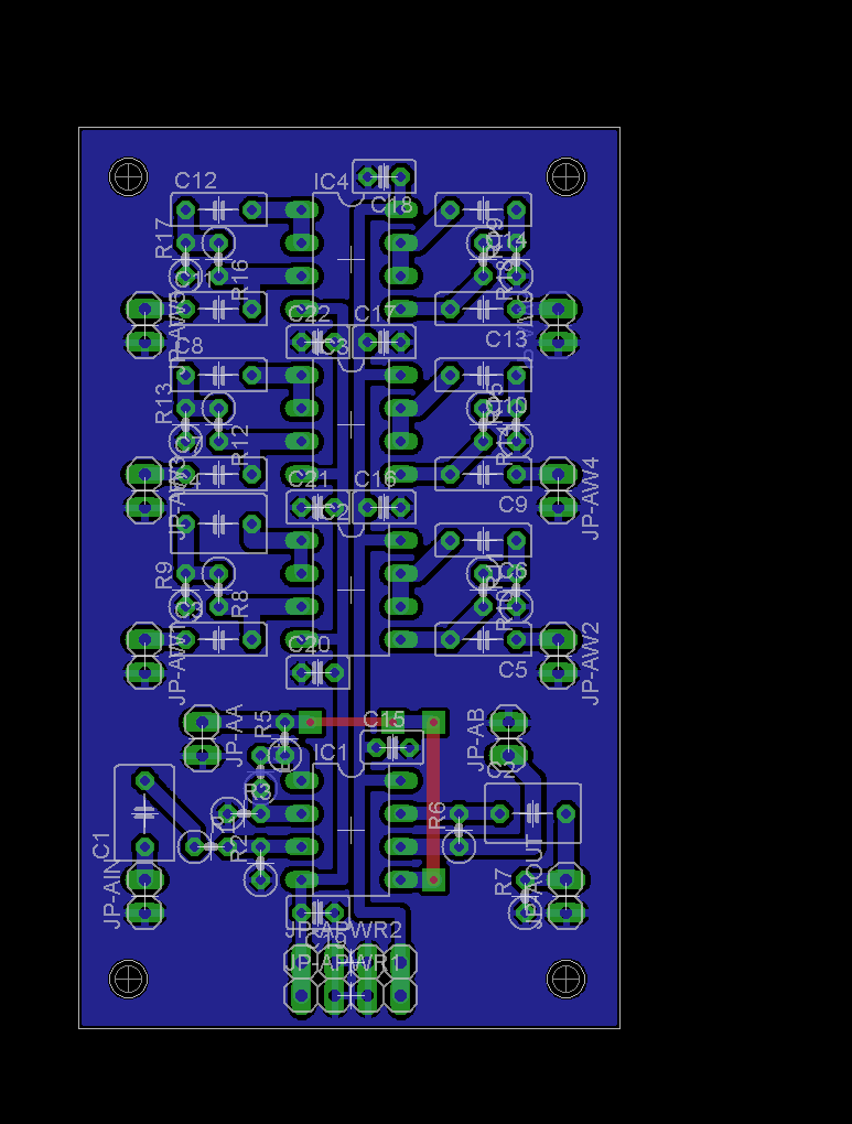
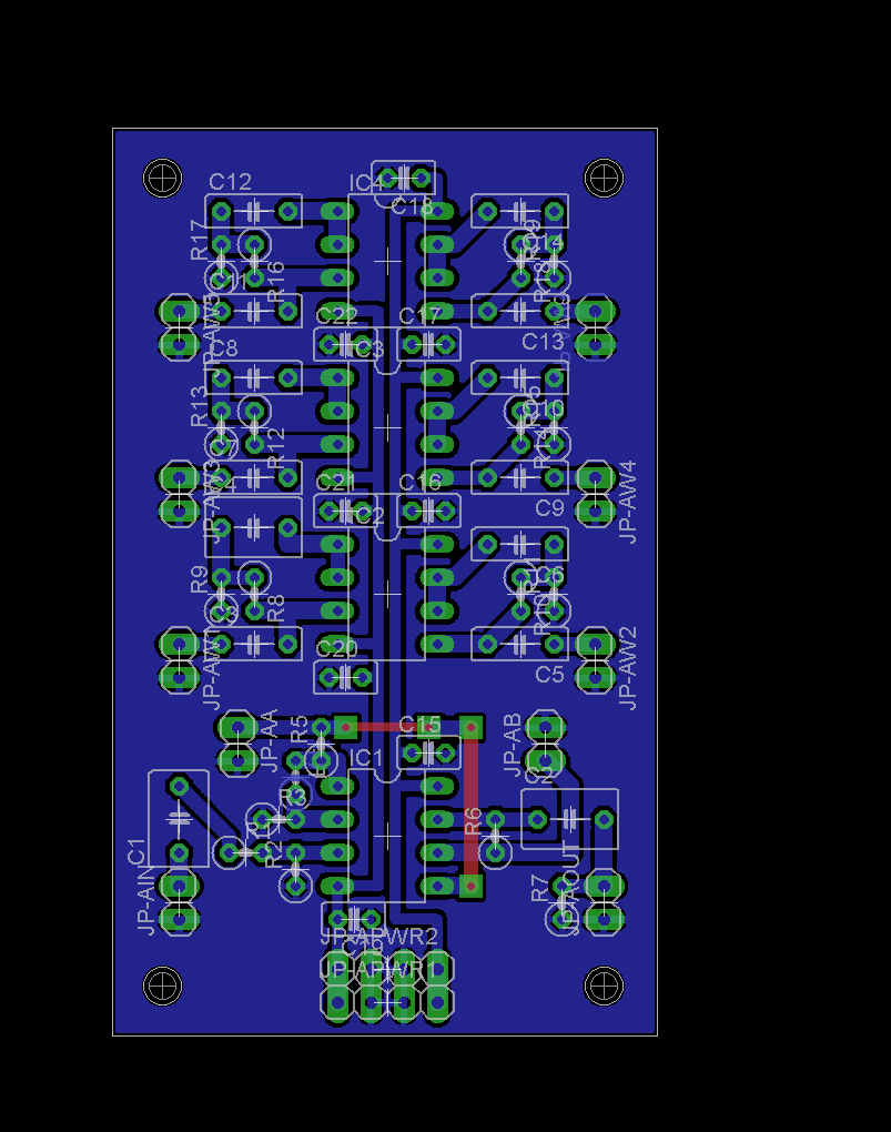
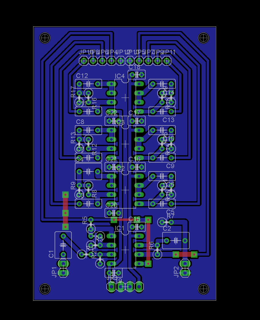
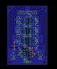
I've abandoned the single-connector design in order to shorten audio paths and avoid parallel tracks. The current design is as shown in the attachment, I'll print it tomorrow and try building a prototype if no significant comments appear.
-
Lyle, thanks for comments, notes! I wanted to place them directly on the IC pins on the copper layer, but right, they're not found on the PCB. I doubt these can be avoided in case of a single 6-pot connector, but I've placed ground plane between each two signals. There are still power leads really close to IC pins, I hope these will not cause much damage. In this design, the EQ is purely analog part so I'd think a single AGND is sufficient. Furthermore, the 'ground shields' leading between audio signals are not leading anywhere so they might really be considered 'shieding traces' as mentioned above. I have these, too. A weirdness happens when I connect grounds of the two power supplies (+/-5V analog and +5V digital) - the analog PS starts drawing as much as 100mA (@230V), but luckily I have lab PS to test with. Power supplies will be designed in the end when I know all the currents needed and all the place available. Once the hardware prototype is ready I'll start programming the DigiPot (AD5206 in my case) part, rest is done already including bus switching. I have also modified the Java for testing, I'll send it back to you if you want it, but as discussed elsewhere, there were just minor modifications - extending channels and adding few more controls... I know the PCB still is not perfect, but a little go/no-go might help :rolleyes:
-
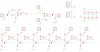
So here are all the schematics and PCB designs, I was busy designing and creating the PCBs during Xmas (I luv Xmas :rolleyes:). However, after building the EQ prototype I found out that it's much too noisy, even with no pots connected I'm unable to get square output from square input... The best result is attached down there. Apparently the PCB design causes the noise (however there was no noise when the EQ was built on a vector board), are there any audio PCB design rules I should be aware of? I'm planning to use shielded cables for connecting the pots, I can also try leading a grounded isolated wire between each two audio signals for test (input, output and pot connections) next to analog ground? I can try to modify the already-built PCB but would like to know whether it actually helps before I re-design (and etch) the PCB... Below is the EQ PCB design as well for quick reference. Thanks. P.S. If anyone is thinking about building such mixer I'd encourage to use AD5204 instead of AD5206, though more ICs will be used AD5206 has no SDO signal and doesn't allow chaning, that's the reason for all the /CS logic found on 2nd sheet... I do already have 20x AD5206 so this is no choice for me :wacko: MBMixer.zip
-
Lyle, thanks, though I have Korg 49 for MIDI control, the tool you're mentioning would definitely help. My current MBMix CC assignment uses CC#91-CC#93 (for old-to-be LPF, BPF and HPF), but since there will be six levels to control plus per-channel Volume (CC#7), Pan (CC#10) and four global L/R buses (not decided on MIDI implementation), I'll use Sound Controller 1-6 (CC#70-CC#75) for controlling the EQ. I'd be happy to use the tool, I didn't figure yet whether the Korg 49 is able to use MIDI channel 'shift' for 8 encoder/8 fader controllers. Looking forward, thanks! P.S. Of course, once the prototype is built I'd be happy to share the schematics and source code! P.P.S. The project wouldn't even start if you didn't start fiddling with PGA, not even talking about TK and the whole MIDIBox :rolleyes:
-
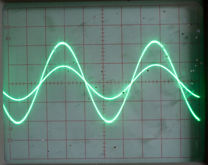
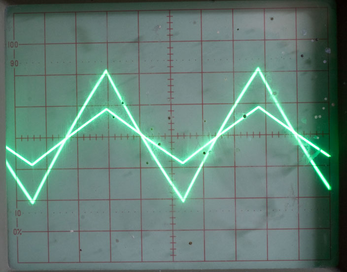
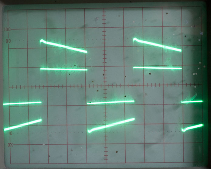
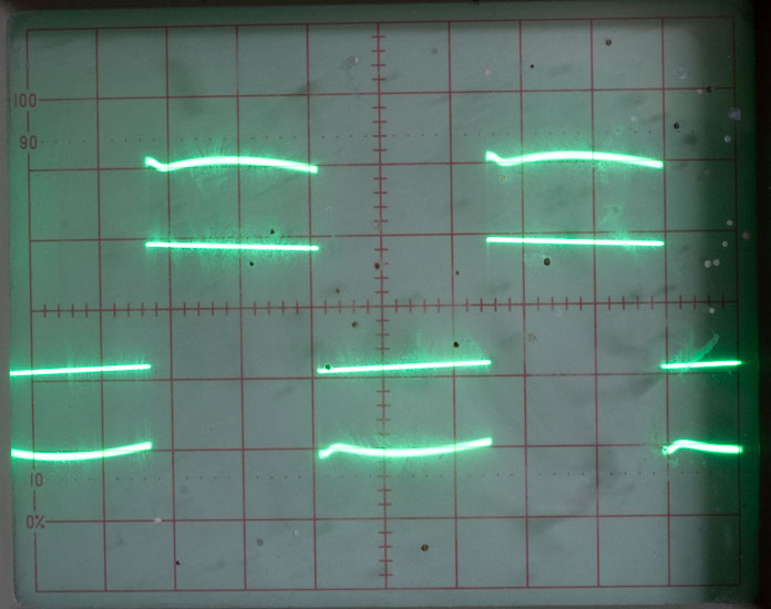
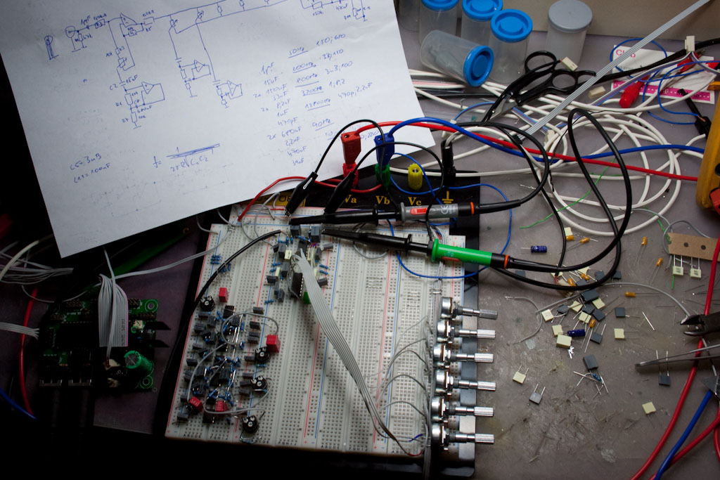
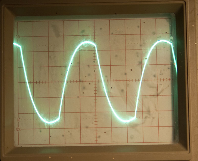
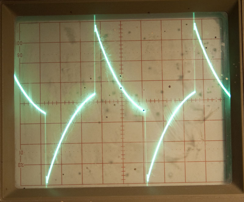
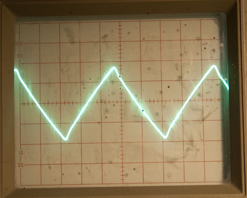
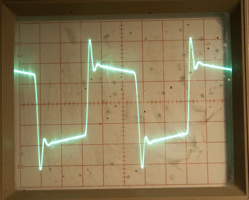
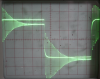
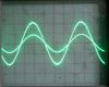
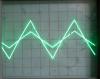
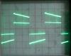
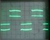
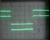
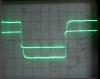
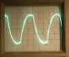
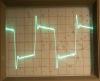
Hi, after several unsuccessful tests with different filters and crossovers I've decided to go for basic 6-band equalizer. For setting the per-band level I'll use digital potentiometers. Since there are 6 bands I'm going for Analog Devices AD5206. The equalizer is a standard one with op-amp input and output buffers and gyrators to substitute inductors in LC pass-band filters. The component values to be used were computed based on my in-shelf supplies to re-use maximum amount of filter capacitors bought for different filter and crossover attempts, but basically the bands are 50Hz, 100Hz, 200Hz, 800Hz, 3200Hz and 12800Hz. Resulting audio signal will be connected to two PGA channels (left/right) to control channel volume. The mixer will be controlled via MIDIBox 64 (or 64E, though 128/128E would be useful for controlling 8 parameters for 16 channels :rolleyes:). THe AD5206 uses the same SPI control bus as PGA4311 is using, so I'll start making the modifications to the software as soon as the equalizers and PGA channels are build. There will be 16x AD5206 and 8x PGA needed for 16 stereo channels plus additional 2 PGAs for total 4 stereo output buses (as mentioned in the previous posts), so the SPI bus control signals (CLK and /CS) will definitely need to be buffered. For results see the thumbnails below, they are (in the following order): - response for 100Hz sine wave, the original (unmodified) wave is cut down in half to see both waves - response for 100Hz triangle wave with original cut down - response for 100Hz pulse wave with original cut down - response for 100Hz "equalized" pulse wave with original cut down - response for 1kHz pulse wave with original cut down - response for 10kHz pulse wave with original cut down - my current desk top with the EQ circuit built on vectorboard (no PGAs and no AD5206s yet) A slight distortion can be seen on all waves (because of shutter speed you may notice the higher-amplitude signal being "thicker" than the other one), it can be seen best on the 1kHz pulse wave. According to the tests performed this is caused by the wires connecting potentiometers with rest of the circuit, there is no ground on the wire. When AD5206 will be used, I'll take care and make the audio lines as short as possible, when possible with analog ground surrounding the lines. Wish me luck...

-
got it, thanks!
-
Strophlex, now I've got the impression that I'm lost in your answer ;-) Not sure what you mean by 'amp' (maybe the op amp?), the only 'amp' that might possible involved in the setup is the PGA chip itself. The current setup is either: (final setup) function generator -+- LPF -> PGA channel -+- oscilloscope +- BPF -> PGA channel -+ +- HPF -> PGA channel -+ or (filter testing setup) function generator -> LPF -> oscilloscope -> BPF -> oscilloscope -> HPF -> oscilloscope The waves above were measured with this testing setup: function generator -+- LPF +- BPF +- HPF -> oscilloscope Since the waves were 10kHz, resp. 100kHz, besides the "substraction" filter construction, I'd assume that the signal passes only through "HPF" though "HPF" is composed of two "time delay" units and summing unit (confirmed by the oscilloscope - no signal was on BPF or LPF). Hmm, looking at the schematics (here, for quick reference), the BPF takes input signal, filters high frequencies using 3kHz LPF and substracts the already filtered LPF signal, resulting in band-pass filter 200Hz-3kHz. Following the same logic, I'd assume the HPF should take delayed input signal (connected to positive input of IC7/B) and substracts BPF signal (connected to negative signal of IC7/B). The delayed signal connects to negative input, however. Am I missing something? If there is no reply for this during the day, I'll try to connect it (as it makes sense to me) in the evening... Strange thing for me is, that the filter does actually work, for sine wave, that is. Again, not sure what you consider being an 'amp' - op amp? The osci is connected either directly to filter outputs (i.e. op amp outputs plus some resistors/capacitor) or after all PGA channels, which has all the filter outputs mixed. The snapshots in my previous post were done with osci connected directly to filter output. Thanks!
-
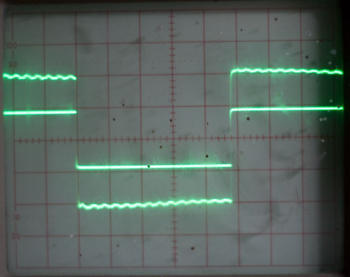
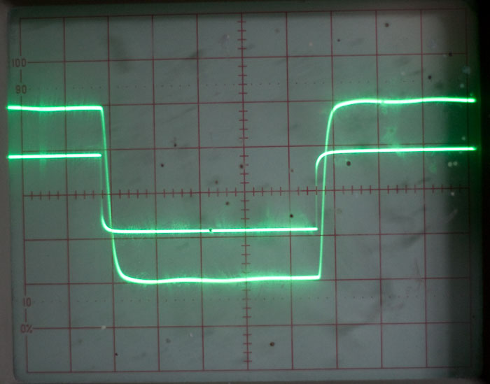
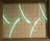
Strophlex, the reason why a filtered non-trivial wave (triangle/square) is distorted is clear to me, the formulas can be found on Wiki or in my school notes. This is not the case, unfortunately. Well, it is, but this is obvious. The problem in my case is that (after new measurements were done) non-filtered complex wave is distorted. In the attachment below, there are two 10kHz waves passing through filter and measured at filter output. The HPF crossover point is 2kHz, so the waves are far above it (10kHz), therefore passing only through HPF. Since they're for some reason distorted already at filter output it's clear that PGA can't do anything about it... I only have one osci probe so I cannot make ALT snapshot of the two waves, but I'll get second tomorrow, promised! :rolleyes: Maybe this is given by the filter construction - I don't know the english word but the filter itself consists of two LPF filters (and time delay units) and the filtered signal is substracted from the original signal in subsequent stages, so since there is phase difference (if phase difference is what I see on the osci) - this is the only place distortion can occur. This filter was chosen since it has 'linear phase', but apparently 'linear' doesn't mean 'flat'... Apparently, I need to make more filter experiments, anything to suggest? Bessel filters seem to have flat phase delay, they'll be probably my next choice for testing... What did you mean by these? Direct generator measurements? These are as straight as expected with no distortion, so the generator works as a charm. Or? Thanks for more info and ideas! What is interesting to me is that for 100kHz the waves are much more what they should be. Is there an explanation for this? (See latter two thumbnails)

-
Yes, same values were used, even the 56.3k resistor is 56.3k, rest is within tolerance of the components, though I know that audio applications are quite sensitive to tolerances, but since MKT capacitors are +/-5% at best, there is not much to choose from... Hmm, the osci is set to DC (I didn't see any difference for sine wave, that's why), I'll change it to AC. I didn't catch the difference, anyway :rolleyes: . I'll take a test look in the evening, thanks for hints so far :rolleyes: If you consider PGA being an amplifier, then yes, but the freq response should be okay for PGA, according to datasheet and web page it's used in professional audio application. Anyway, the interconnection looks like: Functional generator -> filter -> PGA -> Oscilloscope. I never checked whether the output of filter directly is distorted for non-sine signals or not (I doubt it'll be distorted), I always connected the osci after the PGA amplifier. I'll do that when I get back home. I did more checks meanwhile and found out, that when a signal passes through a single filter (>10kHz, i.e. only HPF is involved), the signal is distorted as well (measured at PGA output as mentioned above), do the phase and delays are not involved in this case. I'll see tonight whether the filter output itself is distorted or whether PGA adds the distortion...
-
The only post I found was performed as a guest and mail from his email address mentioned in MIDIBox gallery was rejected. So, again, does anyone happen to have the files? Thanks
-
Hello, I'd like to build 64-pot Midibox64, but since I'm not a good PCB designer (as mentioned elsewhere) but I'd like to have a single PCB I'm looking for several times mentioned Greg McMillan's MB64 PCB layout but can't seem to find it. I know it was designed for pre-MIOS hardware but since PCB erratas do exist I'd like to re-use it, anyway. Does anyone happen to have the files? Thanks, freddy
-
As mentioned before, I'm using ZIF socket for SOIC (from my EPROM programmer). I only have a single one and it's quite expensive (60EUR), I doubt I'll buy more. But since I definitely know I'd like to build PGA-based MIDI mixer, as soon as I make a PCB and solder the PGA (I'll do that at least for a few channels regardless whether I'll use single- or double-stage) I'll free the ZIF socket and will continue with multiple-stage experiments. After a few tries I managed to get the functionality as desired, thanks for explanations and to source comments. There are still few flaws in the implementation, but since I'm using a single channel for now it's usable, though. Up till now I as experimenting with different filters. First, I used a simple 3-channel Butterworth filter (http://users.otenet.gr/~athsam/3_way_active_loudspeaker_eng.htm) but this one suffered from phase shifts and time delays. The resulting sound distortion was audible even by me, this is a 6dB/oct 1st order filter with no linear phase, so this is obvious. Too bad for me that I already bought components for several channels. I'll try to reuse them. Hmm, it's been quite a time I left the uni and I wonder where my calculator is?! Currently I'm using 3-channel linear phase response crossover filter (http://users.otenet.gr/~athsam/3way_active_crossover_with_linear_phase_eng.htm, really a great spotted site, Lyle!) built on a vectorboard: (I managed to fry few of the chips, does anyone know if TI keeps records of the sample they sent? Can I ask for more samples? :rolleyes:) For simple sinewave the crossover works as a charm for the entire 20-20.000Hz spectrum, but for more sophisticated waves (triangle and pulse) the resulting output is distorted: (1kHz triangle) (1kHz pulse) The waves remain far from their meant-to-be shape regardless of filter trim-tuning... Hopefuly someone with audio (and mathematics) skills can tell me what harmonics are missing or are much too loud... However, for really complex waves (music) the distortion is barely audible (at least by my ears and more-than-average quality headphones). One more thing to ask for, if the troubles are solved and I'd be thinking about building the PCbs for multiple channels, I wonder if anyone could help me with PCB routing? Of course, I'd give out the schematics in Eagle but I'm really unskilled with PCB design and effective components layout. I'd really be thankful if anyone could give a hand...
-
Lyle (et al.), I'd like to build 16 chanel full audio mixer with no effects but with 3- or 4-band EQ on each channel. I'd like to place some 3/4-band filter before each channel board to allow control of per-band volume. The idea is that EQ tone characteristics would be controlled by 3 or 4 different CCs, the resulting 16 channels would mix into resulting sound controlled by volume/pan CCs for the same 16 channels. For the input channels, I need 16 boards (possibly 2 cores with 8 channel board each), for post-input 16 "equalised" channels another 4 channel boards (with 3rd core) will be needed. Since there are still just 16 audio channels altogether, standard MIDI channel to audio channel mapping would be used (though it's no problem to workaround this limitation as stated by you several times). So far, so good. What is starting to confuse me are the audio busses to connect to. After reading channel board info, your recommendations regarding line vs. full audio mixer it seems to me that buses will be not needed between the two sets (per-band input and post-input) boards at all, but all PGA outputs for a single channel (i.e. for per-band input channel board) will be connected together forming a single audio feed for second set of input boards (post-input). These post-input channel boards will control volume and pan of the resulting sound and therefor will have L/R busses which will be mixer output connections. Did I get the channel/bus idea right? Is this concept practical or did I miss something while thinking about it? Thanks.
-
Got my batch today, let's get back to soldering ;) Thanks TK!
-
Folks, I have two different C64 PSUs, one is from C64 (whose box is hosting 4x v1 SIDs) and a C64-II PSU. When powering either 4x v1 SIDs or 4x core v2 MB6581 with the old C64 PSU, everything works as a charm. When using C64-II PSU, for the 4x v1 SIDs I get _lots_ of humming in the resulting mixed channel (but the SID modules do work, actually), v2 MB6582 even doesn't power up properly - the 4x20 backlit LCD gets lit, first and third line are blacked out and I cannot get any further, no CS LEDs lit, but the humming can be heard. When I measure the voltages, +12V for SIDs is okay in both cases, but instead of 4.99V I'm getting with old C64 PSU I only get +4.45V for PICs, 5V fan, HC595, LC256, etc. When I measure unloaded PSUs, for the C64 (old one) I'm getting +5.22V, for the newer C64-II barely +4.03V. I suppose this humming is caused by low voltage, as is the "unability to boot" (because of higher load of v2 MB6581), but can someone audio-skilled confirm this before I start opening the C64 PSU? Any similiar experience (i.e. to what to look at inside the C64 PSU)? Thanks.
-
Sure, makes sense. Thanks!
-
Can this be "fixed" (i.e. extended to other cores as well)? I can not imagine a reason why it shouldn't behave the same for all cores.