dcer10
-
Posts
346 -
Joined
-
Last visited
Content Type
Profiles
Forums
Blogs
Gallery
Everything posted by dcer10
-
Hiya stryd_one, That sounds like a top plan but is way out of my capability! I'd love to see it happen and will help in any way I can. All the best, John
-
DIN Buttons problem on my SID please help!! (Renamed)
dcer10 replied to dcer10's topic in MIDIbox SID
Hiya TK, I know I mentioned this to you before but for anyone else reading so they know this isnt the problem I bought my DIN boards from mike. Thanks :} John -
SEQ V2->V3 Migration inc older V2 problems in post too.
dcer10 replied to dcer10's topic in MIDIbox SEQ
Hiya TK, I know I mentioned this to you before but for anyone else reading so they know this isnt the problem I bought my DIN boards from mike. Thanks :} John -
Hi Again mess, I loaded it up and it showed "Hello World" but the screen did not turn off. What amount of time is required to wait? I waited for about 5min but nothing happened. Let me know if you need more testing :} John
-
Wow that was quick, im going to download it and give it a go! Thanks!!!
-
SEQ V2->V3 Migration inc older V2 problems in post too.
dcer10 replied to dcer10's topic in MIDIbox SEQ
Thanks for the reply. This isnt going to be fun, pulling that panel off, or the DIN boards is going to be time consuming. Ive ordered replacement DIN boards, a replacement core, replacement memory, and will pull the front panel off an look at the vero board, which I did cut and test, but could be a problem, Ill check out the bottom of the DIN boards that are there for now. Im ordering all that stuff because it usually seems to be quicker and easier than some of the troubleshooting, which I will attempt anyway while I wait for the parts. Ill let you know if I have any good news :} Thanks again for the help so far. John -
SEQ V2->V3 Migration inc older V2 problems in post too.
dcer10 replied to dcer10's topic in MIDIbox SEQ
A quick update, I tried swapping over the encoder on step 10, same results. I reversed the wires on encoder 14 and it seems better but still a bit odd in that it jumps more than one step at a time some times, which none of the others do, its still progress tho. Step 10 is no longer functioning as is in respect to the encoder, so I swapped out the IC for that SR, it was very random to begin with, then nothing happened at all so I put the original IC back and still nothing. Starting to think theres something odd on that board. I also swapped out the IC on step 14 and had the same thing, random high vaules, I put the original IC back in and now nothing on that step either. Every other step except 10 and 14 works fine. If the board/IC was dead, wouldnt that effect the other buttons and encoders on that SR? What could possibly only stuff up one encoder on a SR and not the others? A short on the board? Something else? Its odd as I seem to get different results each time I turn the machine on! Also I have had no luck with the memory yet either so Im missing out on all that extra midibox goodness of patterns, songs and morphing! DOH! -
Wow! Amazing that it seems possible, I am not capable of making the modifications myself, but if anyone ever does it please let me know,
-
Hiya stryd_one, in hindsight I would have done that, but I could not source the connectors in Adelaide easily to begin with. I now have a source for them for the future. Maybe I should have waited. The upside is that they wont fall off :}
-
Hi, Since LCD screens dim with useage and hence have a limited life span I thought it would be good to have the option, even if turned off by default where after a given timeframe in the setup file the screen would have the power turned off {dont know if thats actually possible with the current core and OS??} and the next key press, knob turn etc would turn it back on but not send any data and the next input would be treated normally. This will prolong the life of all of our LCD screens by a lot meaning people wont have to take apart their probably fragile old midiboxes to swap a screen out in years to come. Maybe its not possible but its something which people who leave their gear on a lot would probably like to see. All the best, John
-
SEQ V2->V3 Migration inc older V2 problems in post too.
dcer10 replied to dcer10's topic in MIDIbox SEQ
Hi everyone, TK, I have uploaded the midiIO128 application to the box. All of the encoders do show a value on the screen as expected. The encoders in question being number 10 and 14 show the following: encoder 10 shows note B_6 with a value of zero, when turned in any direction shows 127 and quickly returns to zero encoder 14 shows CC# 19 with a value of zero, when turned in any direction shows a almost random change between CC# 18 and CC#19 and shows changing values of 0 or 127. It makes no difference if turned left or right, sometimes it shows 18, sometimes 19. The speed of the turning has a difference on which number will come up. I removed encoder 14s connection and wired up a fresh encoder of the same kind and got the same results. I also changed the encoder type to "MIOS_ENC_MODE_DETENTED2" for all of the encoders. This has changed the way the encoders work in relation to my original problem: "2} Some of the encoders are doing unexpected things ie encoder 10 will sometimes generate a value itself, and when I turn it will sometimes change values of other steps, or can sometimes only generate a - signal instead of - or + ie it only goes down not up in note number. Im getting a similar thing with encoder 14 which seems to generate the highest note number {G8 I think} without touching it randomly and also only generates a - signal not a +." In that they seem not to generate the random values or change the surrounding encoders as much, encoder 10 seems to do note G8 from power up and not work after that, on some bootups it will have no value then not work. Also if encoder 10 goes to G8 on boot up then changing the note number on that step with the main datawheel is sometimes temporary and it will quickly jump back to G8 again, other times the new value will stay. Also encoder 10 can land up giving a value to encoder 14 when doing that, generally value A#2, other times moving other encoders may give a value to encoder 10. Encoder 14 generally does work but seems to be in reverse, probably my bad on that one, will reverse it and also check out replacing encoder 10 to see whats happeining there. Strange tho as midiIO128 showed activity on encoder 10, but when you load the sequencer back up it doesnt do anything except its initial value going to G8 or nothing and then it does nothing. The change to "MIOS_ENC_MODE_DETENTED2" makes all of the encoders a bit more stable but there is still a lack of real control as they sometimes do a negative value when turned slowly. Is this something that can be fixed? I have seen many other posts showing this but no real answer on how to get around it. I can live with it if it cant be changed but I may think about fitting + and - buttons onto a remote for finer control for some elements if there is no real solution. stryd_one thanks for your comments also, I will be following your suggestions tonight and tomorrow nite and looking at pulling out the core to see whats going on with the memory problem. I have several other cores sitting about but no working pics for them {my last pic is cactus from my JDM experiments} and I have no "fresh" memory chips left to try, and my other cores have all suffered from the same exact problem so troubleshooting is going to be a nightmare. I liked your suggestion on swapping the DIN boards chips etc and will let you know how I go with that too. Any other thoughts will be appreciated by you guys or anyone else :} Thanks for the ongoing support! Any more would be appreciated very much! All the best, John -
Moebius, I think thats a great idea. I have started a new topic in the fleamarket to see how it goes. http://www.midibox.org/forum/index.php?topic=7777.0 All the best, John
-
Hi, As suggested by Moebius Im looking to start up a group buy for the shunt and the Max525 chips for the Aout boards. To begin with it looks like we will need 13 people wanting 2 525's each as a minimum. If people could express interest on this post and it looks like there will be at least that number of people with their money ready then we can take it further. Also I think it would make sense for whom ever will actually get the large order delivered to be situated somwhere with cheapish shipping for everyone {as best as we can arrange}. I am in Australia, which may not be the cheapest quickest place for shipping for others. I have noticed that shipping out of the USA seems a lot quicker and cheaper than shipping out of Europe, Germany in particular. Can anyone offer comments on any of this, or commit to a buy should we get an order ready? From Moebius's previous comments I think that your investment would be around $50 US in parts for the two chips and two shunts, but dont quote me on it, and the more people wanting to buy the cheaper it would get. All the best, John
-
No worries Twin-X, im happy to help out if I can. What sort of database are you running the forum from if I may ask? MySQL? There are a lot of great tools that im sure you are aware of for site to site database backups either live or otherwise. Im assuming that having the data is the main thing and that the shell site is not a big deal to put back on top of it? Just thinking ahead for possible strategy for the data's long term existance for everyone. All the best, John
-
Hi Everyone, I deleted my posting because I thought it was out of context with the other earlier posts and I didnt feel like getting into an argument with anyone about what sort of web host tech/procedures is better than another, or what could be given out to help for free or if anything should be moved. None of that is of interest to me, I just wanted to help the midibox community out by offering a backup in case of failure, not trying to make comment on if anything would fail for whatever reason, or say anything bad about the current service because I dont do that, and every time I come to see the forum its up, fast, and smooth as! I dont think should be moved, or have any opionion on it other than that it is good, and like all good things can be made better, and if that improvement is free then its also a good thing. PS I dont know what Moebius is suggesting about my deleting of my other posting and saying "nobody did step on the others feet, I guess.", it didnt say anything bad or anything like "stepping on others feet" either, and if anyone can dig it out to show that please do :}
-
DIN Buttons problem on my SID please help!! (Renamed)
dcer10 replied to dcer10's topic in MIDIbox SID
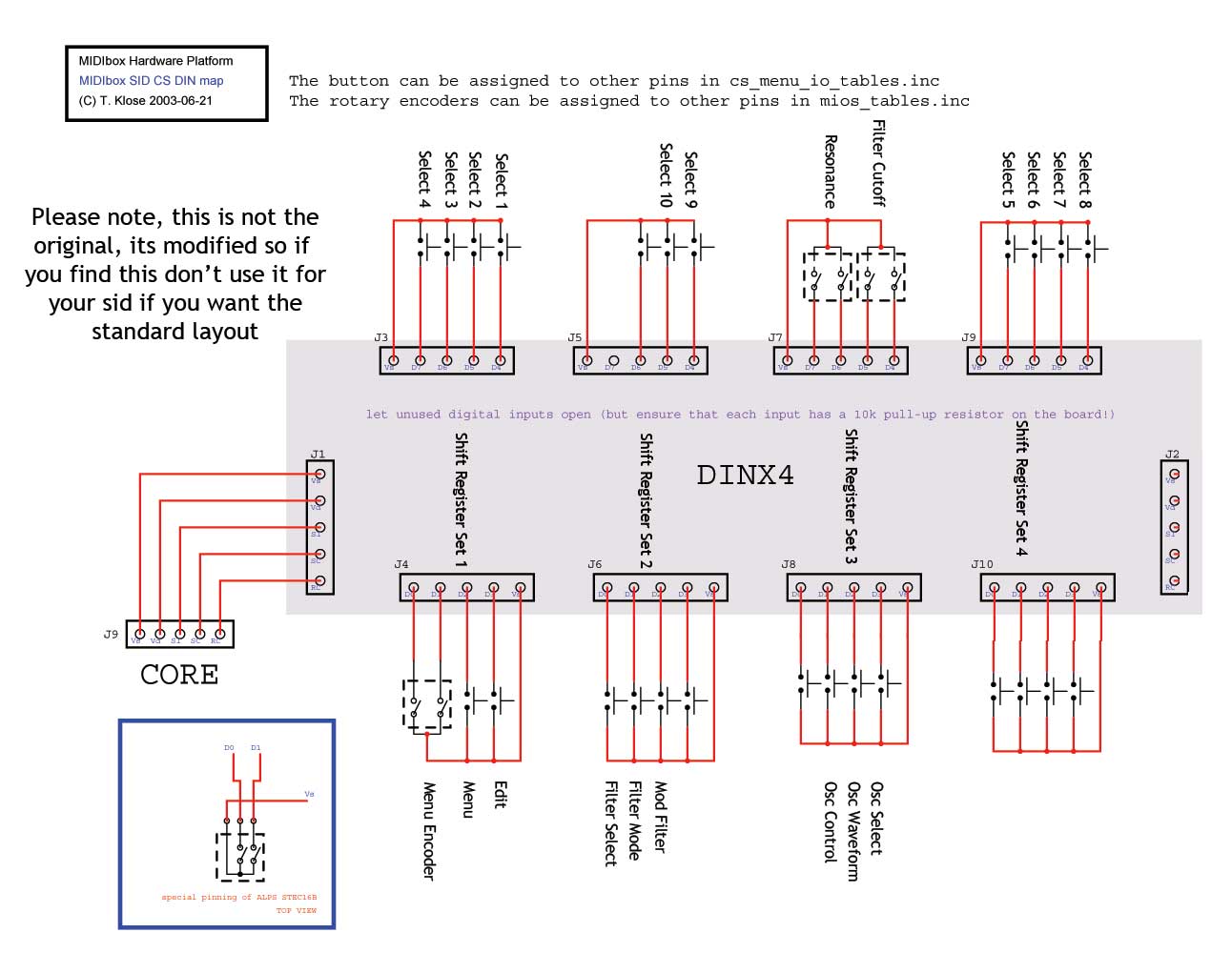
Hi, To make it easier to assist I have condensed all of the previous information into this one reply. Sorry if this puts some of the other peoples previous replies out of context. I have got some problems with the buttons and encoders on the SID. I think the problems are software related, being that I dont know enough about the setup of the application to actually change the application to my button setup. I have the DIN board set up as in the attached image, and here is a link to a zip file to assemble into HEX to upload to my SID http://www.dcerecords.dnsalias.com/Working.zip The resulting HEX works but some of the buttons do unexpected things, and the two extra encoders which I want to do cutoff filter and resonance do decay and sustain. Where would you set up these extra encoders in the application? I did not see them. I have 6 extra buttons whos functions are easy to identify from the diagram which are not doing anything I expect. I would really appreciate some assistance to get this SID up to 100%, its so close! Thanks in advance, John -
SEQ V2->V3 Migration inc older V2 problems in post too.
dcer10 replied to dcer10's topic in MIDIbox SEQ
Hi All, For anyone interested I have made a new post showing many photos during the construction of the sequencer here: http://www.midibox.org/forum/index.php?topic=7770.0 I still however have the problems with the sequencer in this thread, and I also am having trouble with my SID as mentioned here: http://www.midibox.org/forum/index.php?topic=7311.0 And I would really appreciate all of your continued support to get these projects finished. All the best, John -
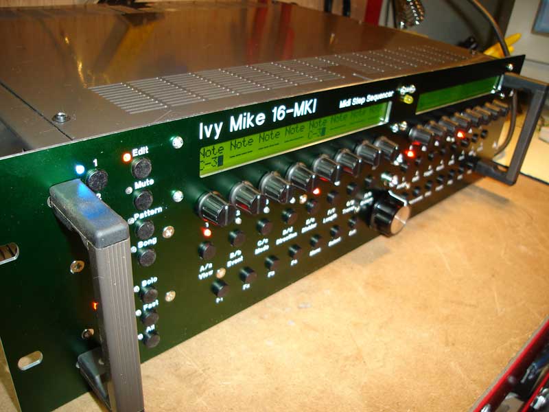
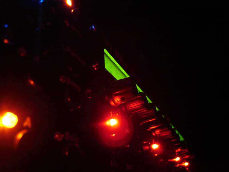
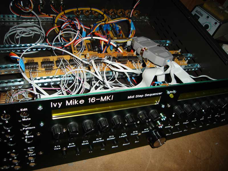
Here are some links to YouTube showing it in the flesh :} http://www.youtube.com/watch?v=e_M4sqamEqI http://www.youtube.com/watch?v=zoR0g6ERny0 They were taken with my still camera in video mode so the quality isnt the best but it gives an idea. I hope that some of these pictures will shed some light on the box construction side of things. If I can be any help to anyone on this topic let me know. Bear in mind im no electronics expert! All the best, John
-
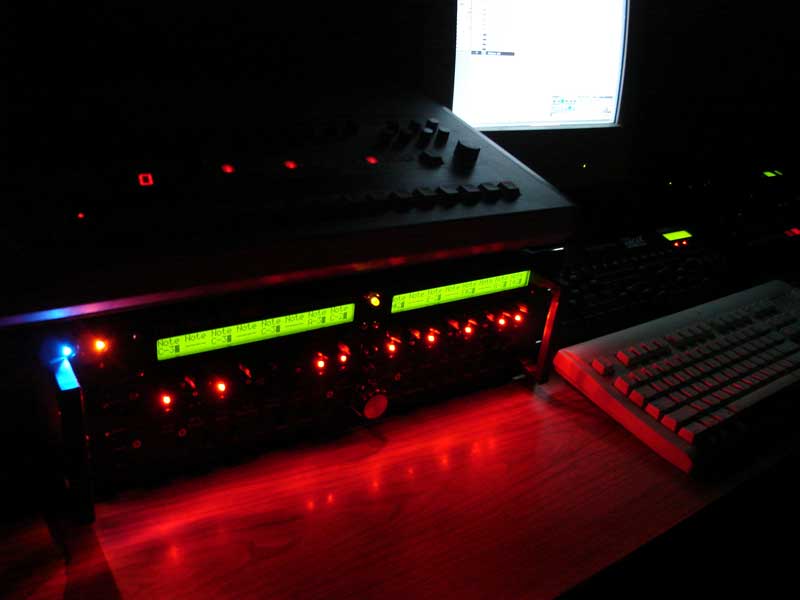
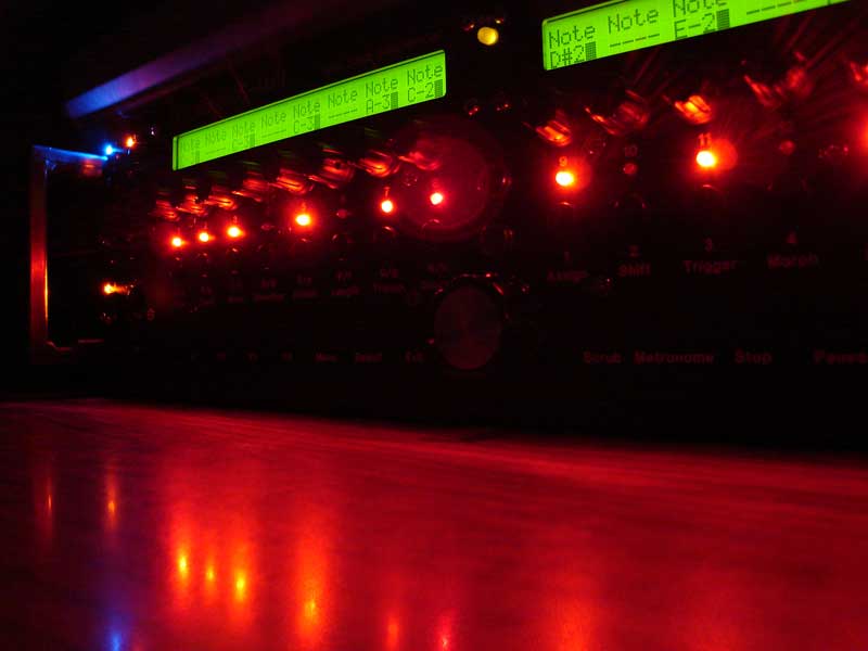
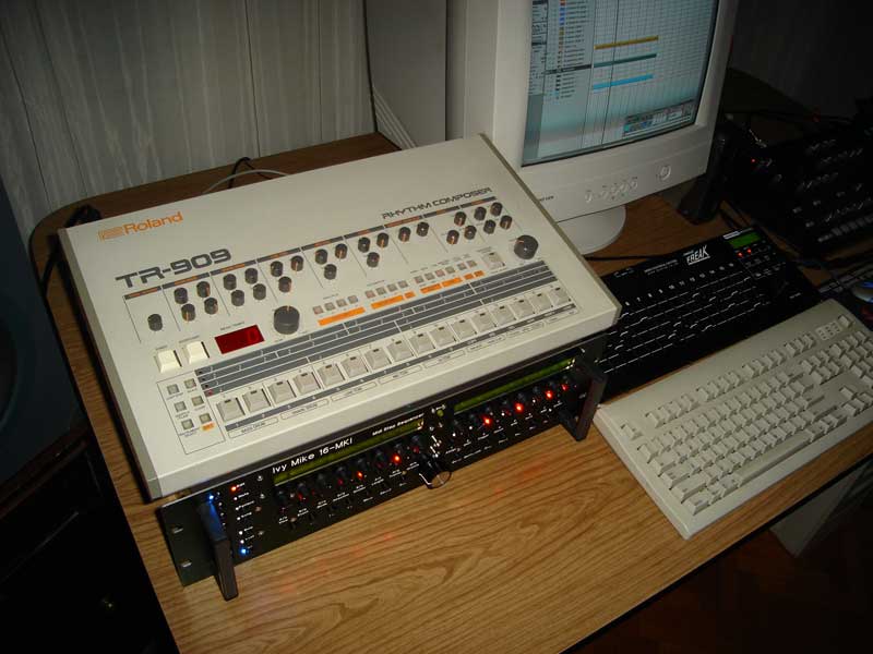
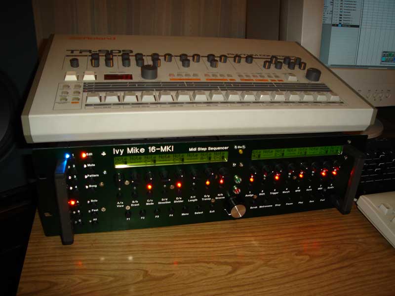
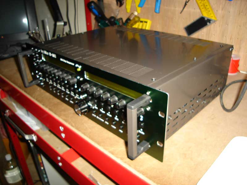
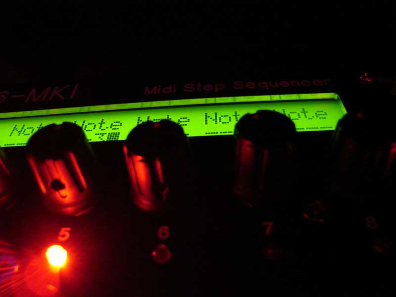
Some more shots of it in my studio.
-
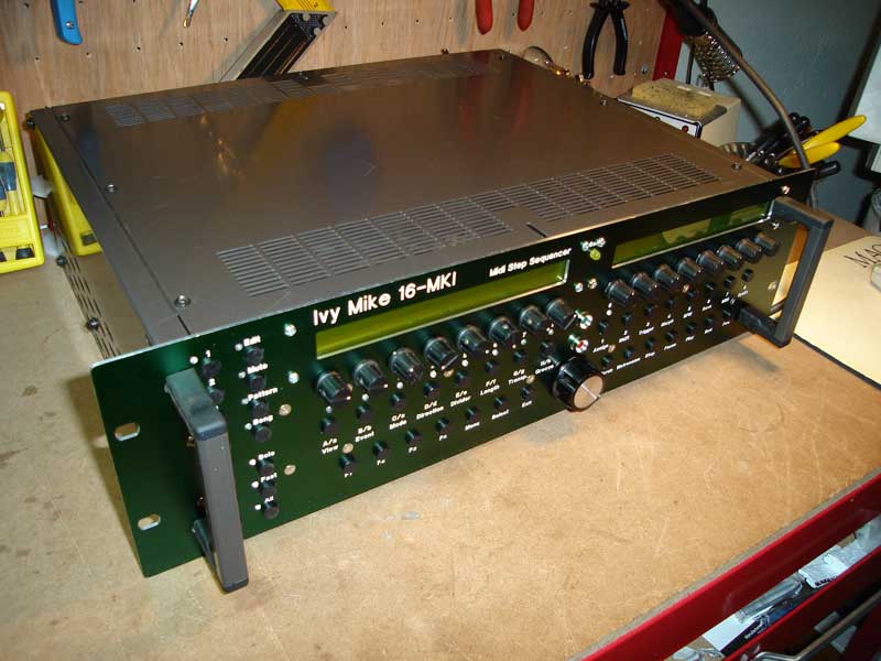
It goes into the studio for some real world tests...
-
Another tip with the front panel is that if you order one and the text is hard to read because it is too dark, which is a problem I had as I left some of the text black like in TK's then you can fill the engraving with liquid paper and when it dries buff it off by hand with a dry clean cloth, it comes up perfect. I have cleaned the surface by spraying mr sheen onto a cloth and buffing the surface of the panel, which makes it look great and also doesnt seem to smear or remove the liquid paper. The best thing about using the liquid paper is that there is no chance of staining the anodised metal in the way paint normally does if you paint outside the letters a little bit. Time to put the lid on and start testing... Unfortunantly this is where I am still at, theres several small problems as listed in this thread: http://www.midibox.org/forum/index.php?topic=7758.0
-
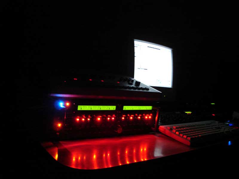
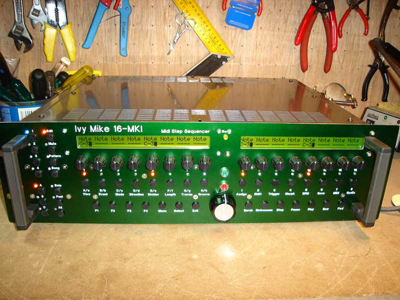
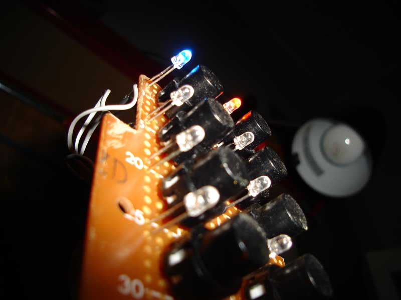
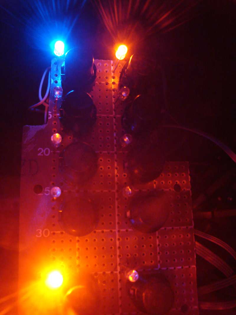
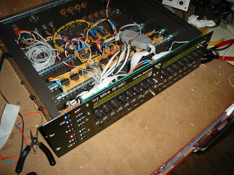
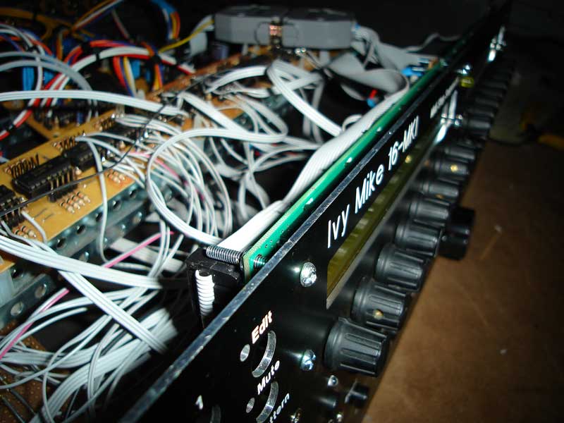
The first signs of life from the LHS button baord followed quickly by the encoders and remaining LED's. I used ultra bright LED's and set them out so I could find my way around by colour code when using it in a dark room like a nightclub :}
-
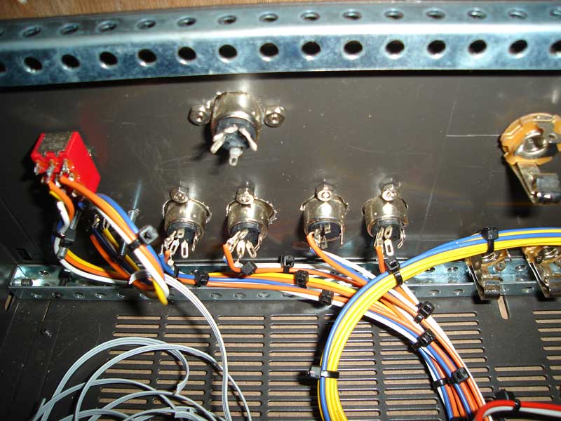
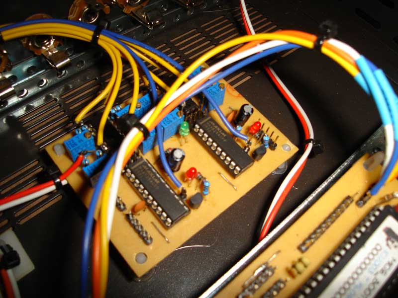
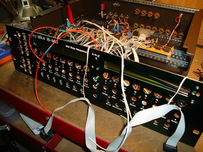
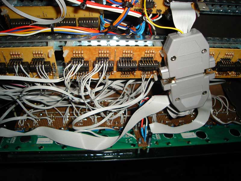
Quickly back to the insides these pictures show the rear panels midi connections, the memory switch {for internal and external memory connected by an Svideo connector on the rear panel}. Also shown is the 1/4" jack connectors for the CV/Gate outputs {currently waiting on my new power supply for +12v,-12V,9v DC to power the Aout and core} and a close up of the populated Aout board , as well as another image showing the front panel without the inner PCB mounted. A tip when ordering the panel, measure the width of your encoder pots before hand and change the hole sizes to suit in front panel designer, same goes with buttons. I didnt do that so the holes are too big. If they were the right size I could have avoided the inner PCB and gone for all panel mount switches. Sorry the order of the pics is getting a little messed up.
-
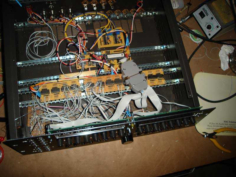
Heres some more showing the panel fitting to the enclosure with the wires connected. The inside boards easily detach from the panel for future work on them. The LHS board is seperate as it is screwed in later so it will fit. The reason why the wires are a little longer than they need {which is not a good thing} is that I needed to lay the panel flat to solder it before fitting, so I needed a bit of extra length for them.
-
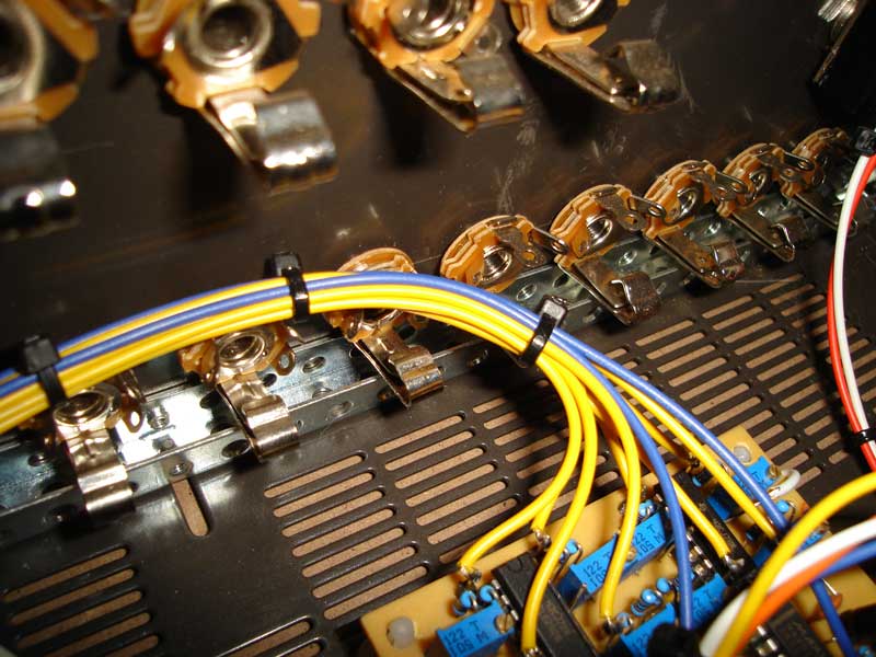
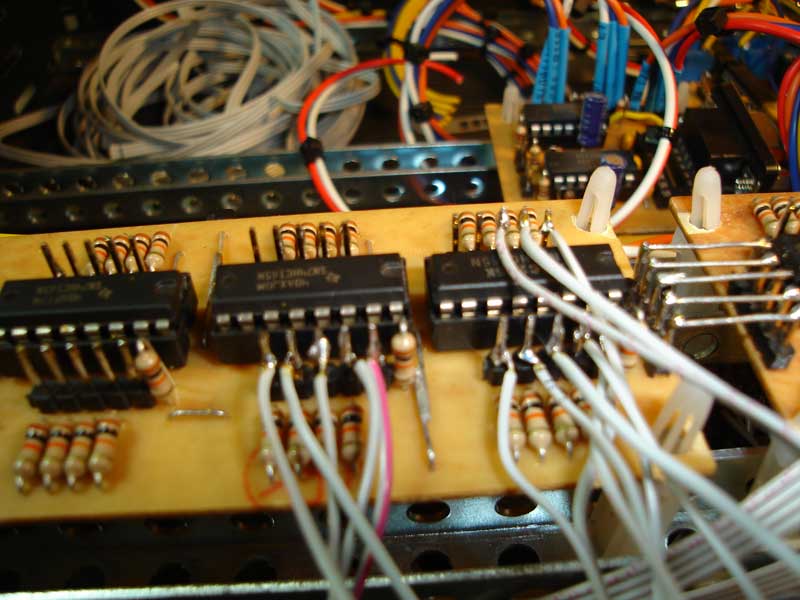
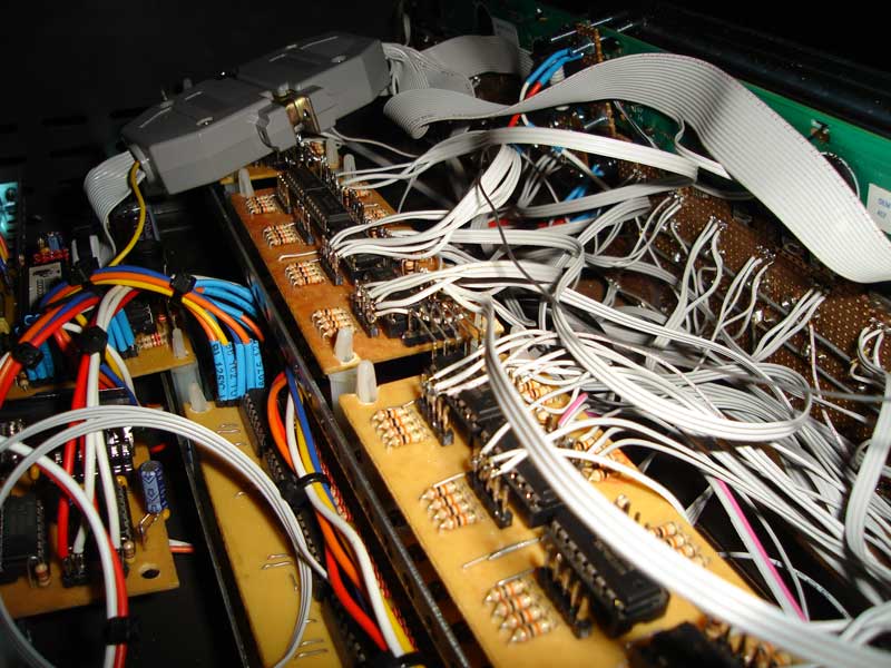
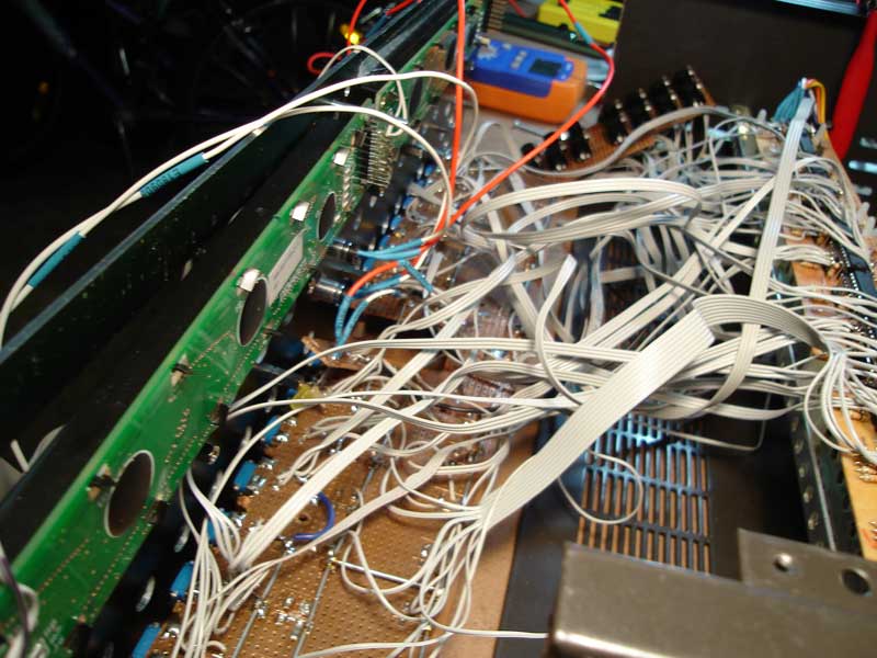
Heres a couple of photos of the connections to the DIN boards. I started using thicker wire, which is too bulky and easily breaks under its own weight at the solder join, so then I moved to ribbon cable which is ugly but much easier to work with and seems to hold better. I stripped the wire ends and soldered to them, then made little hooks by rolling the soldered end in a rolling tool {wrapping it around the end of a pen works too} and then soldering to the SIL pin on the board and putting the hook on, and adding a small bit of solder to join the two.