dcer10
-
Posts
346 -
Joined
-
Last visited
Content Type
Profiles
Forums
Blogs
Gallery
Everything posted by dcer10
-
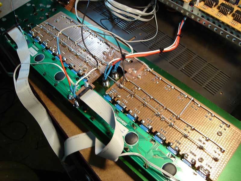
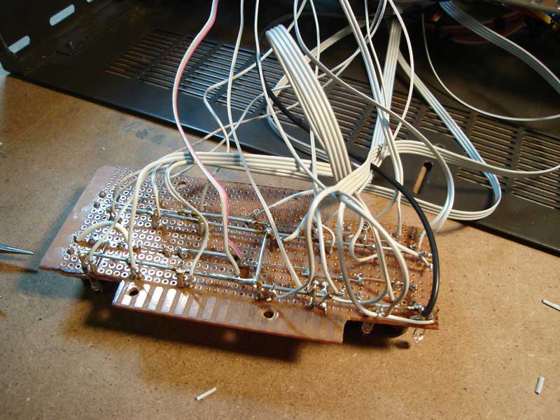
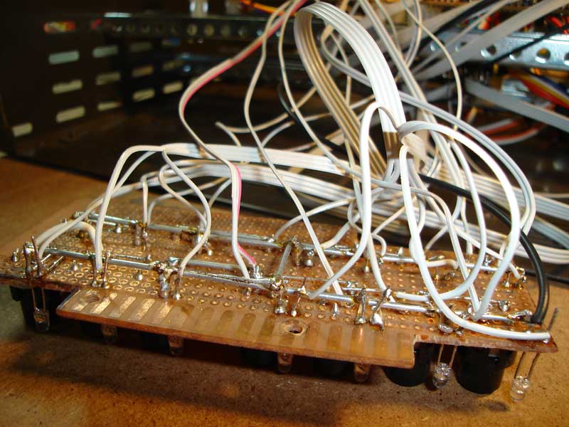
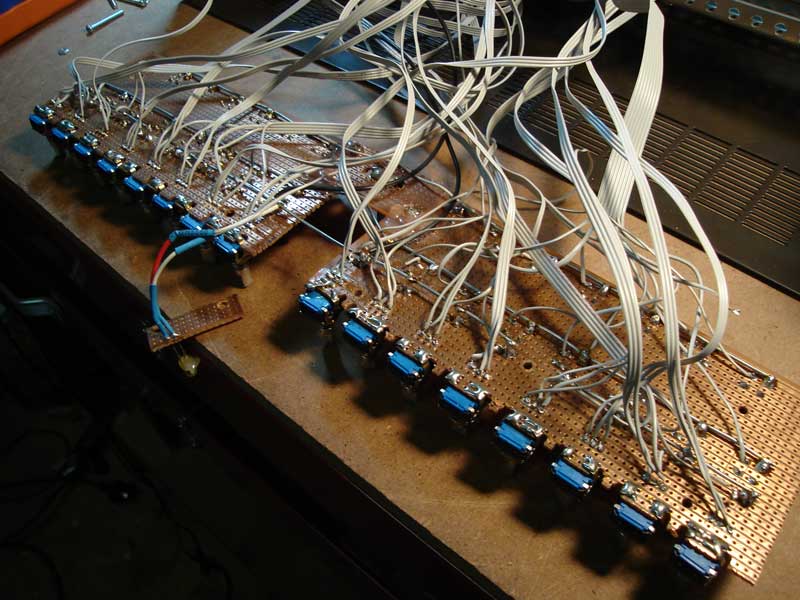
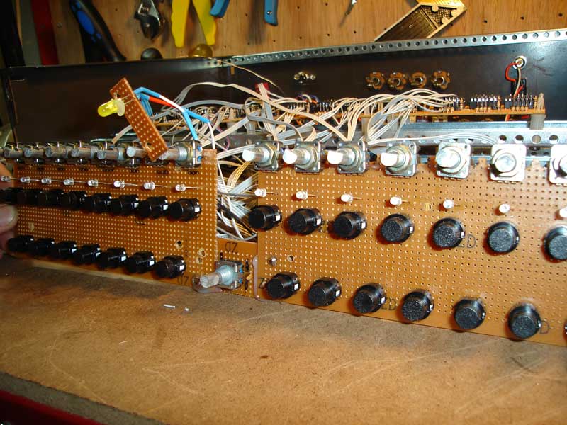
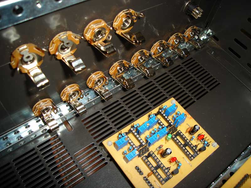
As you can only attach 4 pictures per post heres some more as a part of the last post. These also show the mounting of the button boards with the LCDs etc on the rear. You dont have to do it but I found it easier to make rails to connect the buttons and LED's to for the ground leg only which then only have to be soldered once to the DIN/DOUT boards. I used fencing wire from the local hardware shop to make the rails.
-
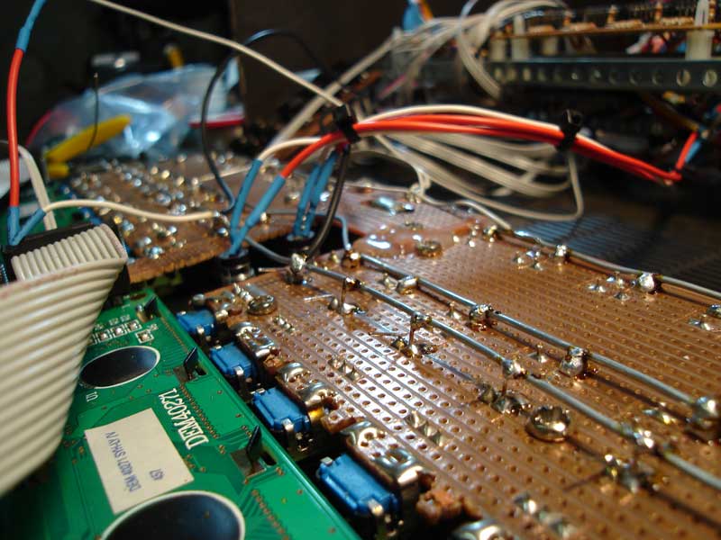
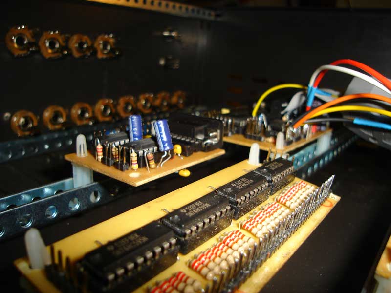
I will skip ahead as connecting the boards etc isnt much to look at and is show in other posts a lot, so here are some images up close of the button boards. I made them from vectorboard, cut them with a hacksaw, drilled them and most importantly, after adding spacers, soldered the buttons and LED's to the board while the board is mounted into the panel to get the right fit. If you try other ways as I did to begin with nothing will line up properly.
-
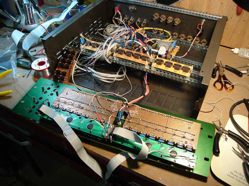
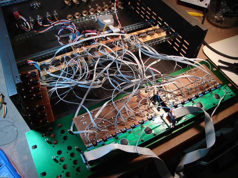
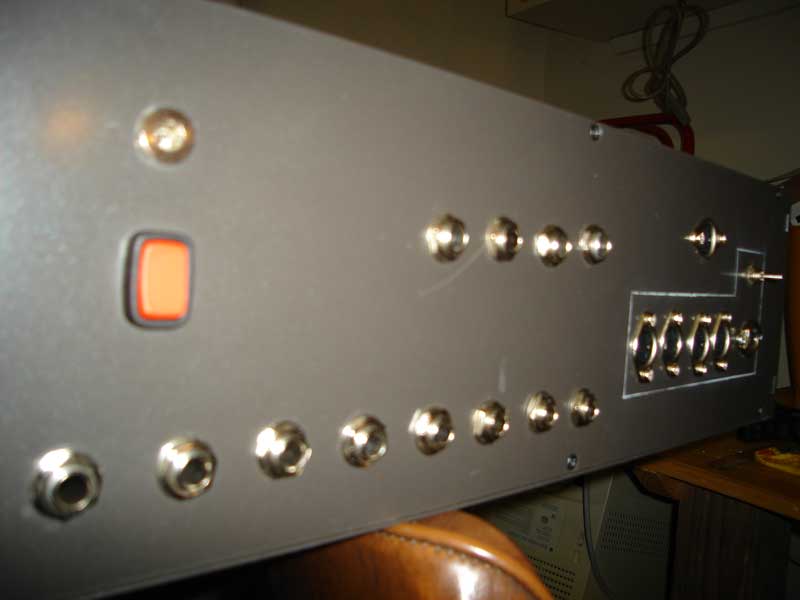
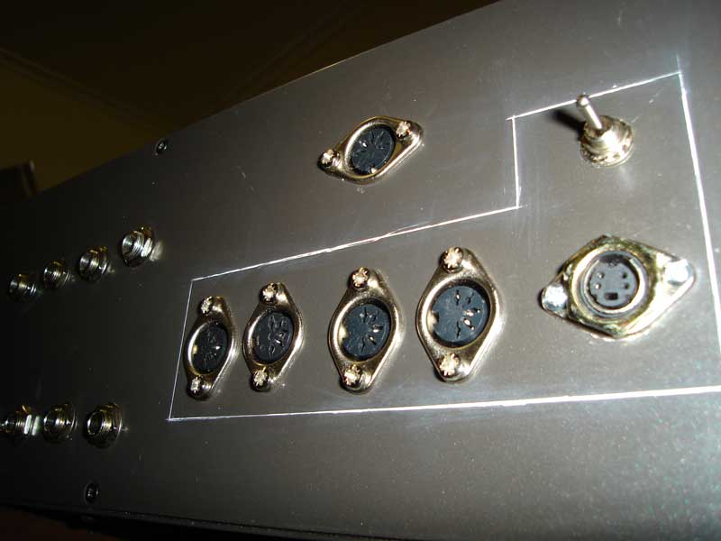
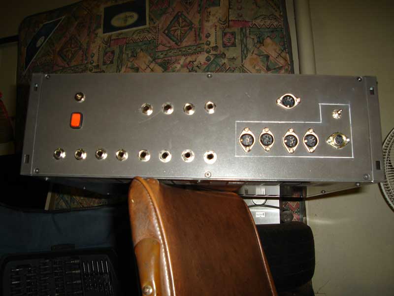
These next photos show the rear panel, I noticed its something not mentioned on the site much so I hope it adds some value to people looking to build a MIOS device.
-
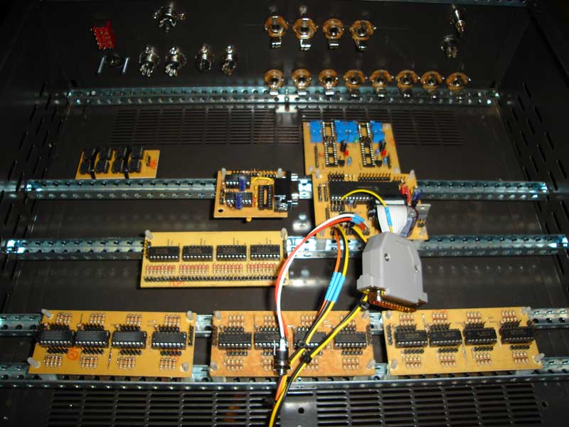
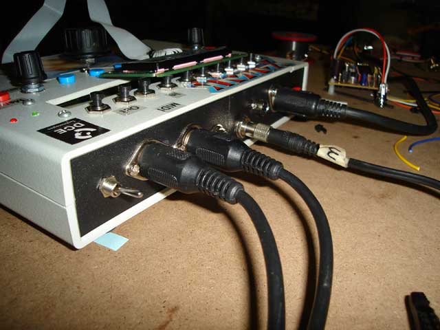
Hi Everyone, Im posting a series of photos here I have taken of my midibox sequencer. I hope they will help some people {Im new to electronics so Im NOT claiming anything here is a good way to do it, just how I have done it}. Perhaps people could offer constructive feedback showing better ways to do certain things for people just starting their constructions? I have a lot of photos and videos of the basic board construction, which I will add on request, but Im assuming that everyone has seen all that before so I wont take the time to include those photos. This first series of photos shows the basic layout I chose of the boards inside the rack housing. I bought the rack housing from Jaycar in Adelaide South Australia, and a note to anyone else who may buy the same rack, it does not fit onto TK's designed front panel, the screw holes are in the wrong place and there is not really enough room for the screens properly. I would suggest moving everything on the panel excluding the left hand side section with the layer and track buttons about 1cm to the left and choosing no screw holes if you also use this rack enclosure. It is the deluxe metal 3RU one for about $100 AU. After saying all that, my panel is essentially TK's panel in anodised green with the holes cut for the LTC module in the front cut with my drill press. I had to mess about a lot hacking the front of the rack and screen mounting to eventually get it to fit the rack enclosure, something I wouldnt wish on anyone! I used the standard blank rear panel which came with the enclosure and drilled out the holes for the CV+Gate, midi, sync etc with my drill press. Featured in one photo is the Dout {unconnected} and antoher shows the Aout {Unconnected}
-
Hi, Tony at http://www.cresttech.com.au/ sells PLEDs. They are a great company, ship fast and really look after you. Not sure where you are from but if Tony cant ship to you {which im sure he will} get them shipped to me and I will post them to you, im in Australia where he is. As stryd_one said they dont seem to come in 40x2 but at least its a start to have a supplier. All the best, John
-
Thanks very much for the diagram bill, thats just what I was looking for, now I just need to figure out where to solder the other ends and how to configure the application to use those pins. Again excuse the noobness im not used to MIOS and where everything goes yet! All the best, John
-
Hiya TK, The mp3 sounds awesome! The MBHP FM does sound like its more feature packed than the TX. I especially like the wavetable idea. I dont like the sound of more noise being added to my existing setup tho! Your file did not have too much noise compared to the signal generated. How much of the sound was from the other chips? I have usually only used presets on this particular synth as the programming interface is terrible {TX} but have always wanted to lay out a control surface which {incorrectly} translates the programming interface of the TX into something more like the panel on a Juno 106. I know how different the two are, and that you would have to limit the TX to certain parameters to fit this kind of control for example only using a certain alg to get the waveform of the normal osc {limiting the proramming potential but adding simplicity to the layout} and then following a normal sort of signal path thru envs, filters etc like on a Juno. This would be cool if you could have one box as an FM sound module, then layout seperate panels for each configuration of how you might use it and hot swap them over when you like ie one panel suited for making FM drums, one for FX sounds, one for normal analog bass/synth sounds, and maybe one which has access to all the normal functions. You could have a different "feel" of synth from one tone generator for every day of the week :} I just dont like programming sounds on FM synths, too hard but I like the sonic potential! I do have a program for my kenton control freak that sort of does that, and its good, but maybe building your FM synth with a series of custom interfaces would suit my FM needs more?? Its funny, I had not seen your pictures and I have the same mixer and was thinking of putting a SID into it :} Thanks for the advice on the synth, John
-
Hi Moebius, "But dcer10 - Why don't You start supplying MAX525s and the reference chips?" If I was an electronics store I probably would. But im not, im a hobbyist. I have no idea of the minimum orders, or the economics of either of the stores, nor the risks taken, and as a consumer I dont need to know these things or debate them. I appreciate the presence of both shops and wouldnt want them to take a bad risk leaving everyone with nowhere to buy the kits. All I know is I would like to buy these chips rather than order free samples so I dont feel like a scab and there is nowhere I know of to do that :} Maybe someone could look at doing a 1000 part order after seeing what other communities use the chips and trying to sell 1/2 off to them? These chips must be used in other similar projects??? I know for one I could not afford to do the order. If anyone was ever interested in a group buy as suggested by TK count me in! All the best, John
-
"Vintage" macs and their use with MIOS
dcer10 replied to dcer10's topic in MIDIbox Tools & MIOS Studio
Hi Adam, Whats the possibility of porting the software to a non java platform? Are there enough people still using os 9 to make it worth while? I would like to keep using it as long as possible even tho I have many more powerful options, simply because of OMS and the cheap multi port interfaces. All the best, John -
Hi Meeshka, Thanks for the reply, at least I know whats going on. I would love an updated version which remembered the settings, but I understand how difficult this sort of thing could be as I used to project manage software development for Audio Video streaming software. I especially understand when you are making something for free for people its even harder, im greatful to have MIOS studio at all and thank you for your efforts, complete or not :} At least I know its not my PC thats the problem! All the best, John
-
SEQ V2->V3 Migration inc older V2 problems in post too.
dcer10 replied to dcer10's topic in MIDIbox SEQ
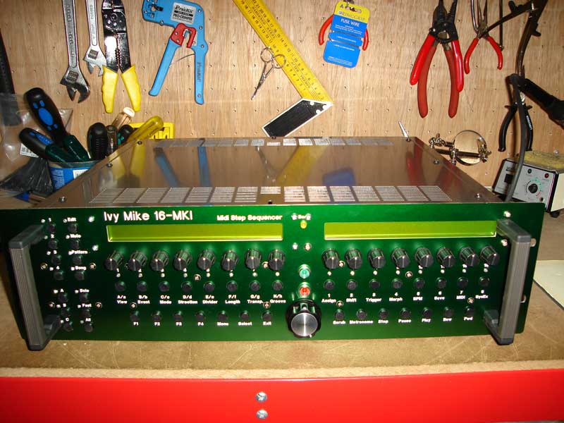
Hi everyone, Thanks for all your positive comments. I cant take credit for the front panel as it is TK's design, I have just tweaked it a bit. The main differences between this design and the one you download from the midibox sequencer page for manufacture with front panel designer are: 1} I requested a green anodised metal from them 2} I added my artist name Ivy Mike etc to it for a personal touch {would have liked to have the midibox logo etched in too, but was too hard to get a front panel designer object of the logo, can someone make it for download??} 3} I added the LTC module and mounted the in/out lights for it on the front {the out light is not working, the LED is ok, the wires are ok, the LTC has been fine in other projects and shows in light but not out} 4} I used expensive ultra bright LED's which I bought from aztronics here in Adelaide and chose some complimentary colours for the different modes 5} I pumped up the contrast on the LCD's using the trim pots on the core 6} I chose some nice trimpot covers Apart from those minor changes the panel is the same as TK's. I will post a seperate topic with the making of this sequencer with detailed photos of every step of the constucution esp the panel so people can see the inside and copy it if they like. I had to try to figure out what to do with the panel as there were no clear photos showing the panel setup, and the panel itself did not fit my rack case, or any of the pots I ordered so maybe this could save people some time on theirs?? In regard to the technical bugs... stryd_one, when you say fried, do you mean for 1} the core or memory board? Ive had this same problem with each core I have built, and have only fixed it once by replacing the whole core and memory board and memory chips all at once. Is there a program suitable for testing memory chips one by one as I have now got around 30 of them, some wont work im sure, but i would like to be able use the working ones. Kind of hard at the moment without a working memory module in the seq, and my sid is sealed up tight and too hard to open. Also for 2, when you say fried, do you mean the din board or the chips? I will try to go thru TK's suggestion re the DIN board. I hope its something simple as its too much work to rewire any of those boards!! I will continue to investigate the faults and let you all know whats going on in hope of getting this box finished :} On a very good note {excuse the pun!} I had a great jam session with the sequencer last nite, and it exceeded my expectations, even with the current bugs and no memory!!! All hail MIOS! All the best, John -
Im just curious, whats the average bandwidth requirements for the forum? How much data is used per month? Im only asking as I may be able to offer a a linux server here in Australia which is on a 24mb/s connection which could be used as a mirror, or at least a place to back the data up. Its already used for business applications which require high uptime so its ready to go and pretty secure. Im not even sure it would help, but worth asking!
-
Has there been any updates on this? Is the V3 sequencer going to happen still with the current hardware or will people need to build the IIC board? Im very keen to update my V2 to V3 when its possible. The converstations so far looked like it was going to happen, then that there was a bug, then it was worked around with the use of the IIC board, then the bug on the pic was gone, now it isnt, does that mean you just need an IIC board? Its all a bit confusing! Im in no rush for it, still working some bugs out of the seq v2 ive built, Im keen to start getting parts for the V3, can someone give a clear upgrade path requirements list? Thanks in advance, John
-
Hi everyone, Just wanted to see if I was the only oddball out there still using mac classic ie OS 9.2 or earlier in their workshops and studios? I am using a beige G3 and a 9600/350 with OMS and an Opcode Studio 4. Im my opionion you cant beat that for midi. I have several high powered PC's with all the latest HW/SW for audio/midi but I still get more out of OMS and the studio 4, especially when using studio patches. What im asking is, if people out there are using old macs still, what tools if any have you found are useful when working with your midiboxes? I have used a program simply called sysex which is a sysex librarian, it however seems to not load up the transfers easily to the midiboxes. I would like to use MIOS studio or similar to dump hex files, is ther an alternative? Even loading up .syx files from the midibox site doesnt work well because of the mac file translation problems it wont see it as a system exclusive file, but it does see it as a PC simple text document. If someone out there wanted to they could stuff some .sit files with .syx files made on macs for use with midibox gear and then everyone using old classic macs could talk to their midiboxes :} I know that a lot of pro studios still use OS 9 with pro tools, and with OMS, I know its old, but its tried, tested, trouble free {as much as a computer could be!}, cheap, and easily obtainable, all things I thought MIDIBOX users like! Perhaps other users could comment on their experiences using older mac OS's with midiboxes?? Thanks, John
-
Hi, Sorry for the long delay, have been finishing the sequencer :} Im ready to try to add the sync now. The din jack is in the rear panel, Im ready to solder on the lead. Im not sure how it is soldered to the DIN jack, I guess its the outer pins? Dont know which goes where.. Also im still unclear on the last post as where to set it up in the code. Which file is this from? I havent seen the terms LATC, LATD etc used before and im unsure of what they are, or where to locate them on the core. Im also unsue which ones connect to which plug on the DIN. Im using the Aout and 2 LCD's so but no ain, so what would be a suitable setup for me, which file do I modify, and which cables go from what jumper to where on the DIN plug? Also I dont suppose you {stryd_one} would know where to get the extra gates from on the Aout board? Ive got the two shown on the schematic ok, but wasnt sure about the other 2 {is it two more on the core or more?} and which order they are in. Sorry for so many questions, im obviously new to this all :} Thanks, John
-
Hi all, Has anyone else had the problem that mios studio doesnt remember the midi in/out settings and you have to re set this up each time you load the app? Im using winXP sp2 with a midisport 2x2 usb midi interface {which is known to have some problems with this sort of thing} but I also get the same results using any midi interface on this PC. Was just wondering if there is an easy solution that could save me a lot of time, esp when debugging and you forget this problem and start looking for other reasons why the midi i/o isnt working!! :} Thanks, John
-
From Australia and wanting a source for some motor faders
dcer10 replied to oberklaus's topic in Parts Questions
Hiya guys, im here in Adelaide, maybe alone on the midibox front?? Just thought id add that theres a company in adelaide called mixmasters who also do repairs on massive mixers, which sometimes have motor faders, they may be able to supply you with them second hand, or may be able to point you towards a supplier? There are a few audio electronic genisuses there who may be able to hunt them down being Damien and Rob. Dont expect it to be cheap tho! Good luck! John -
There is a guy who sells replacement keys for 909's on ebay from time to time who has ones with blue LED's in them. I will post you a message if I see them come up again. Good luck :}
-
I did finally get some from a kind midibox user {moxi}, and then they arrive from maxic too! They too a very long time to get here, months but pics came quite quickly. Also cOnsumer, I would love to buy the parts from a supplier but I have tried all the electronics stores in Adelaide but none can get it and Ive had no luck buying them online. It would be nice if mike or smash took up a supply of the 525's and shunts to sell an Aout kit at their shops.
-
Hi everyone, I am thinking about making the FM synth after my sequencer and sid are finsihed, which will be soon. I already own a Yamaha TX81Z {like 8 DX100's in a rack} and love it, is this synth much better? Unfortunantly the old FM synths all have the problem of a lot of noise, does this one share that downfall? Are the chips really that hard to solder? Im not sure if this is the project for me since I have the yamaha already, can someone sell me on it? I really want to build it but with the time and money investment im not sure this is the one to do unless someone can tell me its totally amazing as a synth. Does the filter have more resolution than the TX81Z {8 positions only, very steppy, need to re trigger the note}. Thanks, Jonh
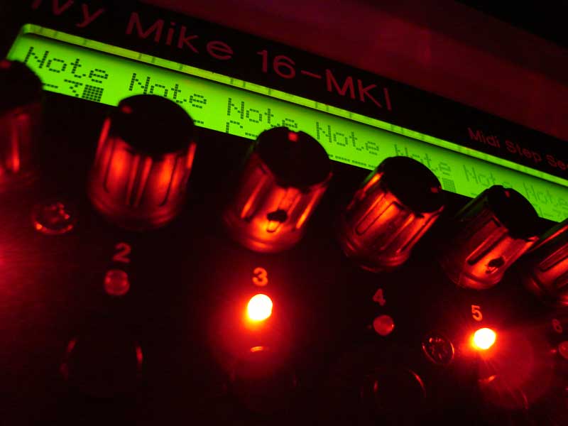
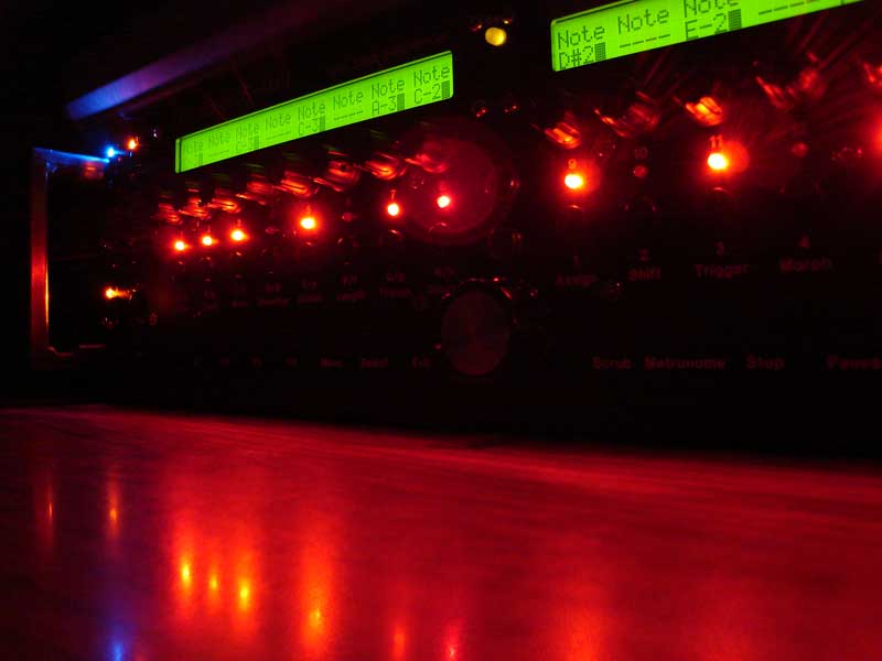
-
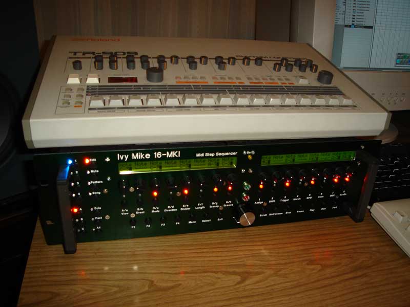
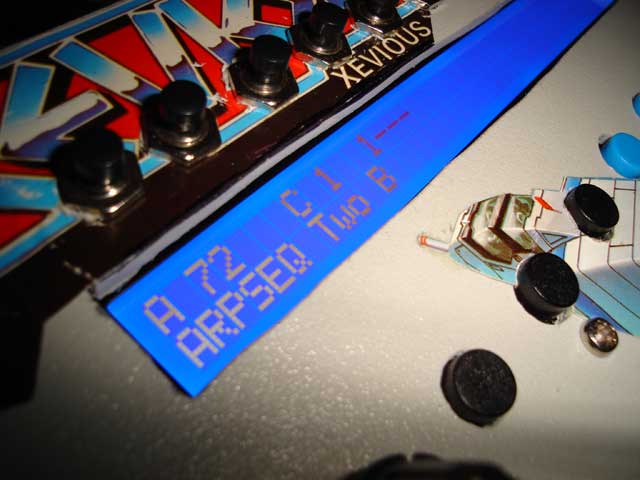
Hi everyone, After nearly a year ive finally finished putting my midibox sequencer into its box and closed the lid {perhaps pre maturely!}. Everything is working great except for a few small bugs being: 1} When I connect up a bankstick board the seq wont turn on, or wont register the memory, this is the case even when using a single chip soldered directly to J4 with some wires in an IC holder. 2} Some of the encoders are doing unexpected things ie encoder 10 will sometimes generate a value itself, and when I turn it will sometimes change values of other steps, or can sometimes only generate a - signal instead of - or + ie it only goes down not up in note number. Im getting a similar thing with encoder 14 which seems to generate the highest note number {G8 I think} without touching it randomly and also only generates a - signal not a +. 3} All of the encoders {all bought from smash TV, the ones without the button} are a bit unstable in that it usually will not like small movements and often flickers between the previous value and the current value instead of the next value. This makes exact notes difficult to get, and also makes getting to some menu settings hard. Heres some photos too of the sequencer, I might put up a bunch in a seperate post as I have taken lots during the construction. Some of those may help people but these are just to give an idea of how its turning out. If anyone can help with some suggestions Id appreciate it. Thanks in advance, John
-
PIC16F877 and JDM Programmer: Programming Failure
dcer10 replied to banneduser's topic in Testing/Troubleshooting
For anyone using the JDM still, I have the following advice as I have had a lot of problems with it. I followed all the instructions I could find about the HW/SW configuration. From what I can see you do not need PortIO or any extra software. One thing to look out for in xp is that you can have a serial port IRQ conflict without winddows telling you anything about it. On my system I had to look into the control panel and in the hardware section go to resources under the com port you are using, there may be a red circle around one of the settings, if so this is your problem. In my case I solved it by disabling com3 so com1 could have the irq which was in conflict. This wont help everyone, but it does confirm that the JDM works under windows XP when you follow the instructions on the MBHP site and have your hardware setup correctly, there is no magic to it, just checking every possible problem along the way. John -
Hi All, I still cant get a shunt, I have requested samples from maxic 3 times now, other samples arrive but the shunt does not. Does anyone have a spare one? Thanks, John
-
Hi eveyone, Anyone looking for any of the LCD displays in Australia or near by should check out: www.cresttech.com.au They are solid, I dealt with Tony Csendes there and the screens are very high quality, reasonably priced, well packed and ship quickly. I enquired about every kind of display used in mios and they seemed to be able to get them all and in various colours too. Their contact details are: Unit 46 / 41-49 Norcal Road Nunawading 3131 Victoria Australia Tel: +61 3 9873 8830 Fax: +61 3 9873 8802
-
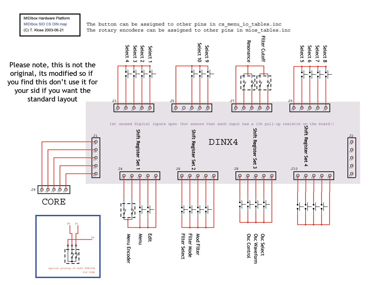
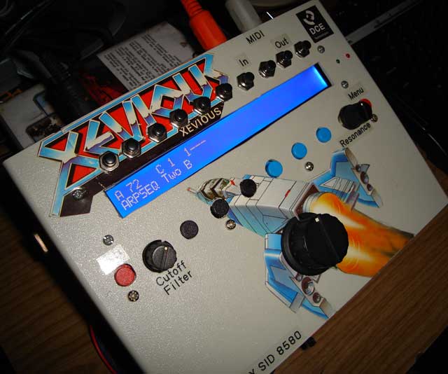
Hi, Im having some troubles connecting up my SID, I'm at the last steps now, but having difficulty with the buttons in a couple of respects. I have attached a picture of the layout of the DIN board I am using (only one of them) in my CS. In the setup_8580.asm file it refers to the cs_menu_io_tables.inc file which has all of the shift registers and pins listed. Considering the layout for my DIN board what would be the correct entries in the cs_menu_io_tables.inc file? Im confused as to the layout of the SR's and pins. Can someone point me in the right direction for my example please? Here is what I have now in the mios_tables.inc file (just the encoder section) ;; additional CS encoders ;; SR Pin Mode ENC_ENTRY 0, 0, MIOS_ENC_MODE_DETENTED2 ; Osc delay/transpose/assign #1 ENC_ENTRY 0, 0, MIOS_ENC_MODE_DETENTED2 ; Osc attack/finetune/assign #2 ENC_ENTRY 0, 0, MIOS_ENC_MODE_DETENTED2 ; Osc decay/portamento/assign #3 ENC_ENTRY 0, 0, MIOS_ENC_MODE_DETENTED2 ; Osc sustain/release/assign #4 ENC_ENTRY 0, 0, MIOS_ENC_MODE_DETENTED2 ; Osc release/pulsewidth/assign #5 ENC_ENTRY 0, 0, MIOS_ENC_MODE_DETENTED2 ; LFO rate ENC_ENTRY 0, 0, MIOS_ENC_MODE_DETENTED2 ; LFO depth ENC_ENTRY 3, 5, MIOS_ENC_MODE_DETENTED2 ; Filter CutOff ENC_ENTRY 3, 7, MIOS_ENC_MODE_DETENTED2 ; Filter Resonance ENC_ENTRY 0, 0, MIOS_ENC_MODE_DETENTED2 ; Env depth/assign #1 ENC_ENTRY 0, 0, MIOS_ENC_MODE_DETENTED2 ; Env attack/assign #2 ENC_ENTRY 0, 0, MIOS_ENC_MODE_DETENTED2 ; Env decay/assign #3 ENC_ENTRY 0, 0, MIOS_ENC_MODE_DETENTED2 ; Env sustain/assign #4 ENC_ENTRY 0, 0, MIOS_ENC_MODE_DETENTED2 ; Env release/assign #5 ENC_EOT and here is what I have in the cd_menu_io_tables.inc file (just in the buttons section) CS_MENU_DIN_TABLE ;; Function name SR# Pin# DIN_ENTRY CS_MENU_BUTTON_Dec, 1, 0 ; only valid if rotary encoder not assigned to these pins DIN_ENTRY CS_MENU_BUTTON_Inc, 1, 1 ; (see mios_tables.inc) and CS_MENU_USE_INCDEC_BUTTONS == 1 DIN_ENTRY CS_MENU_BUTTON_Exec, 1, 2 DIN_ENTRY CS_MENU_BUTTON_Sel1, 1, 7 DIN_ENTRY CS_MENU_BUTTON_Sel2, 1, 6 DIN_ENTRY CS_MENU_BUTTON_Sel3, 1, 5 DIN_ENTRY CS_MENU_BUTTON_Sel4, 1, 4 DIN_ENTRY CS_MENU_BUTTON_Sel5, 4, 7 DIN_ENTRY CS_MENU_BUTTON_Sel6, 4, 6 DIN_ENTRY CS_MENU_BUTTON_Sel7, 4, 5 DIN_ENTRY CS_MENU_BUTTON_Sel8, 4, 4 DIN_ENTRY CS_MENU_BUTTON_Sel9, 2, 4 DIN_ENTRY CS_MENU_BUTTON_Sel10, 2, 5 DIN_ENTRY CS_MENU_BUTTON_SID1, 0, 0 DIN_ENTRY CS_MENU_BUTTON_SID2, 0, 0 DIN_ENTRY CS_MENU_BUTTON_SID3, 0, 0 DIN_ENTRY CS_MENU_BUTTON_SID4, 0, 0 DIN_ENTRY CS_MENU_BUTTON_Link, 0, 0 DIN_ENTRY CS_MENU_BUTTON_CC, 0, 0 DIN_ENTRY CS_MENU_BUTTON_Edit, 1, 3 DIN_ENTRY CS_MENU_BUTTON_Osc_Sel, 3, 3 DIN_ENTRY CS_MENU_BUTTON_Osc_Ctrl, 3, 1 DIN_ENTRY CS_MENU_BUTTON_Osc_Wav, 3, 2 DIN_ENTRY CS_MENU_BUTTON_Osc_RS, 0, 0 DIN_ENTRY CS_MENU_BUTTON_LFO_Sel, 0, 0 DIN_ENTRY CS_MENU_BUTTON_LFO_Wav, 0, 0 DIN_ENTRY CS_MENU_BUTTON_Env_Sel, 0, 0 DIN_ENTRY CS_MENU_BUTTON_Env_Ctrl, 0, 0 DIN_ENTRY CS_MENU_BUTTON_Fil_Sel, 2, 0 DIN_ENTRY CS_MENU_BUTTON_Fil_Mod, 2, 1 DIN_ENTRY CS_MENU_BUTTON_M_O1Ptch, 0, 0 DIN_ENTRY CS_MENU_BUTTON_M_O2Ptch, 0, 0 DIN_ENTRY CS_MENU_BUTTON_M_O3Ptch, 0, 0 DIN_ENTRY CS_MENU_BUTTON_M_O1PW, 0, 0 DIN_ENTRY CS_MENU_BUTTON_M_O2PW, 0, 0 DIN_ENTRY CS_MENU_BUTTON_M_O3PW, 0, 0 DIN_ENTRY CS_MENU_BUTTON_M_Filter, 2, 2 DIN_ENTRY CS_MENU_BUTTON_M_E1, 0, 0 DIN_ENTRY CS_MENU_BUTTON_M_E2, 0, 0 DIN_ENTRY CS_MENU_BUTTON_M_L1, 0, 0 DIN_ENTRY CS_MENU_BUTTON_M_L2, 0, 0 DIN_ENTRY CS_MENU_BUTTON_M_L3, 0, 0 DIN_ENTRY CS_MENU_BUTTON_M_L4, 0, 0 DIN_ENTRY CS_MENU_BUTTON_M_L5, 0, 0 DIN_ENTRY CS_MENU_BUTTON_M_L6, 0, 0 DIN_ENTRY_EOT What I am confused about in particular is how the encoders for cutoff and resonance will work. The main data encoder has inc and dec pins listed, but the others dont so which do you connect and which do you reference in this file? I have not complied with these new settings yet as im not sure they are correct. Also another problem is that I am getting some strange button and encoder behaviours. For example, I have only connect up the Menu and Edit Buttons and the main encoder to do a small test. This is done using the default setup_8580.asm file (not one custom for my setup). The menu button and encoder are actually the same in both setups tho so they should work ok I think. The encoder wheel works, but when turning it slowly between the notches (its detended) the program change on the screen looks like its going to happen (flicks) but reverts to the current program. Turning the wheel faster works ok. When pressing the edit button nonthing happens, when pressing the menu button nothing happens, but when pressing the menu button and holding it then pressing edit and releasing edit it shows a menu of some sort. Also while no buttons are pressed the screen flickers a bit, but when I press and hold the menu button this goes away and the screen looks normal. Ive also attached some new pictures for anyone interested in the progress :) Thanks in advance, John