dcer10
-
Posts
346 -
Joined
-
Last visited
Content Type
Profiles
Forums
Blogs
Gallery
Everything posted by dcer10
-
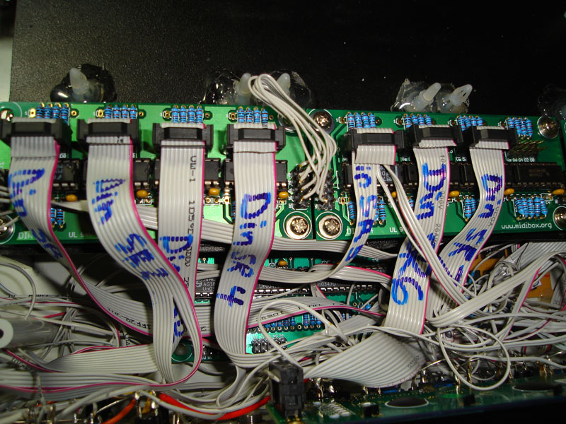
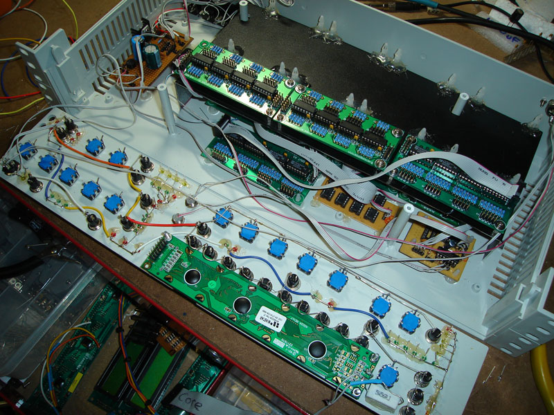
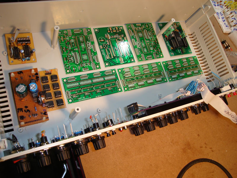
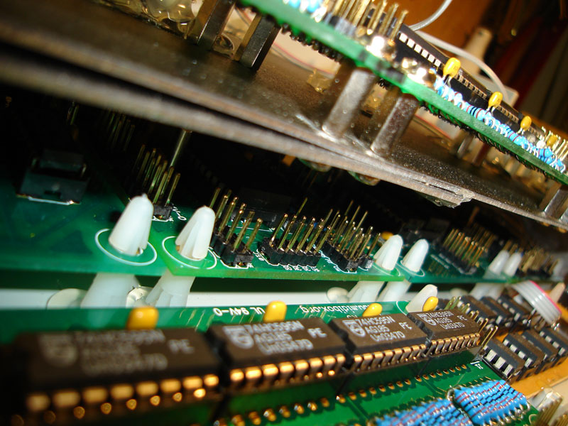
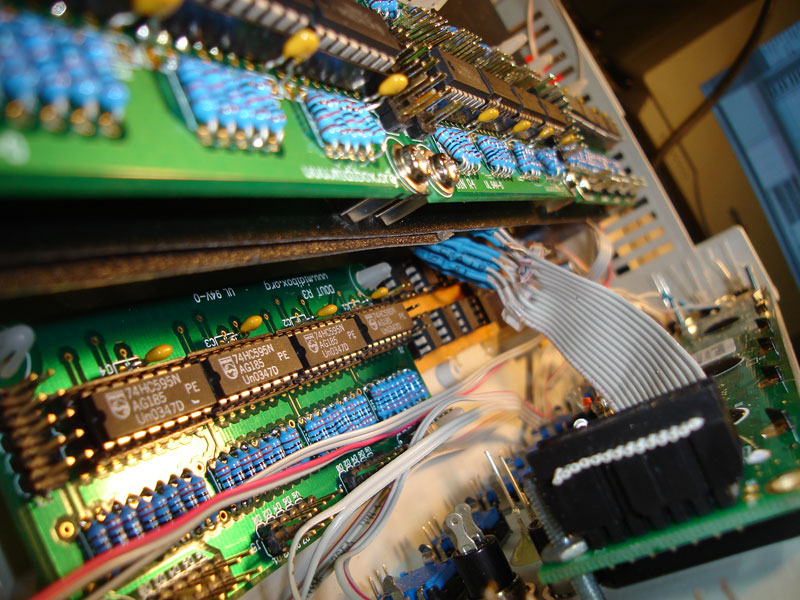
more... What a mess of cables!!
-
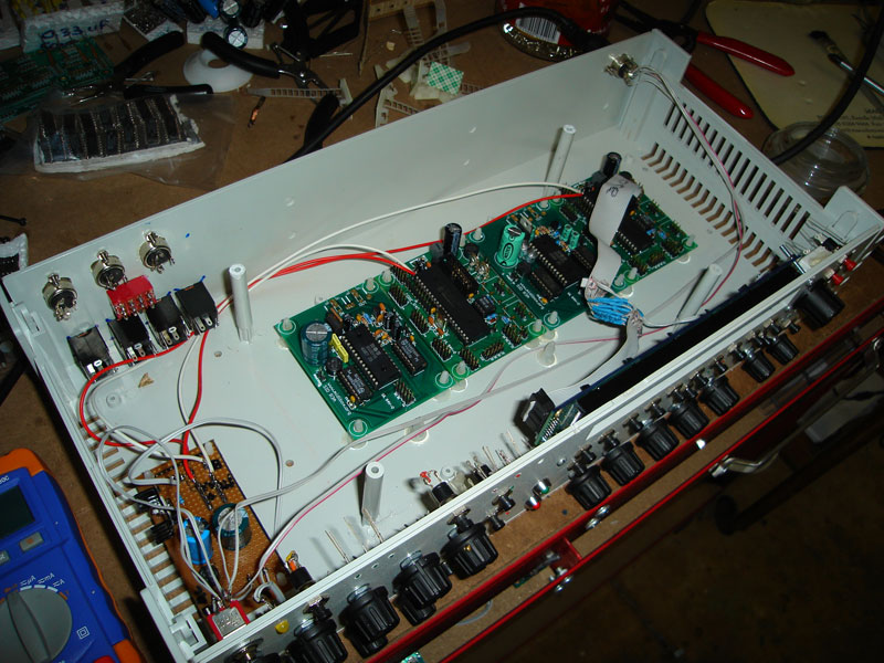
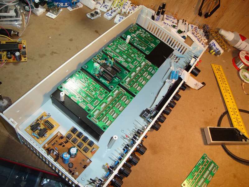
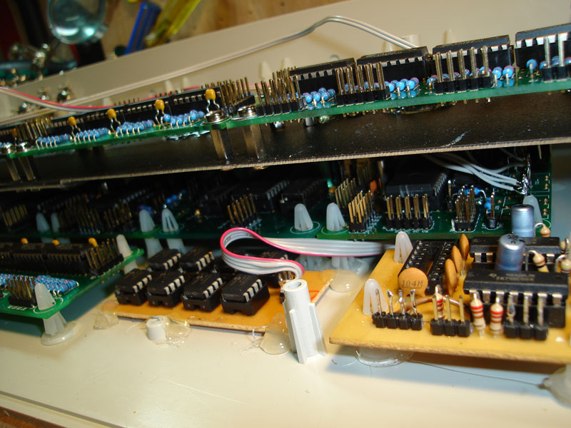
more again...
-
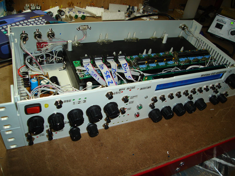
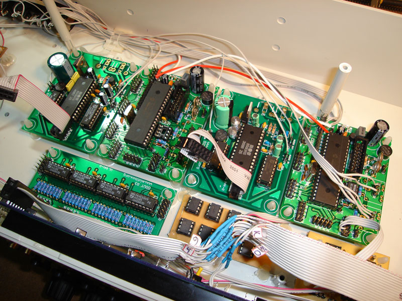
some more...
-
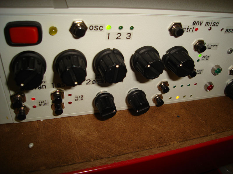
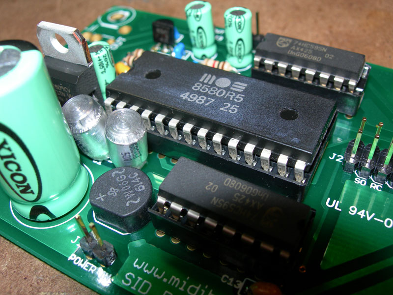
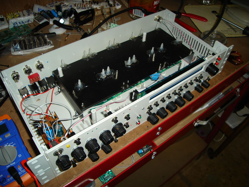
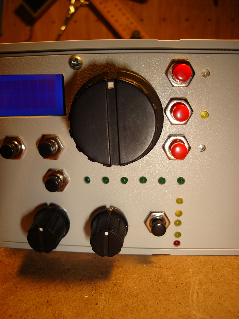
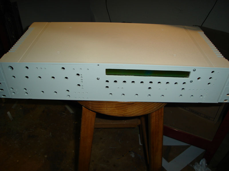
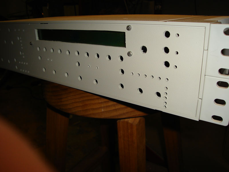
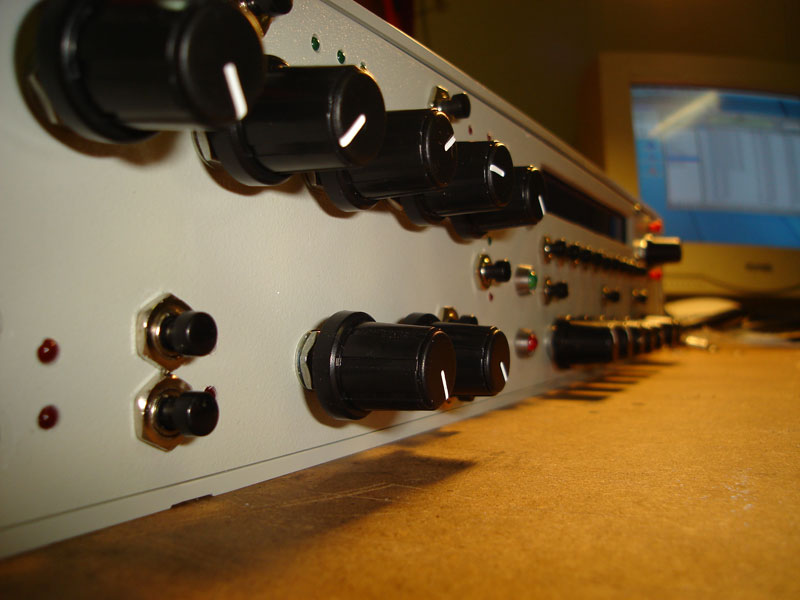
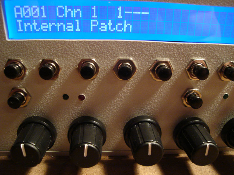
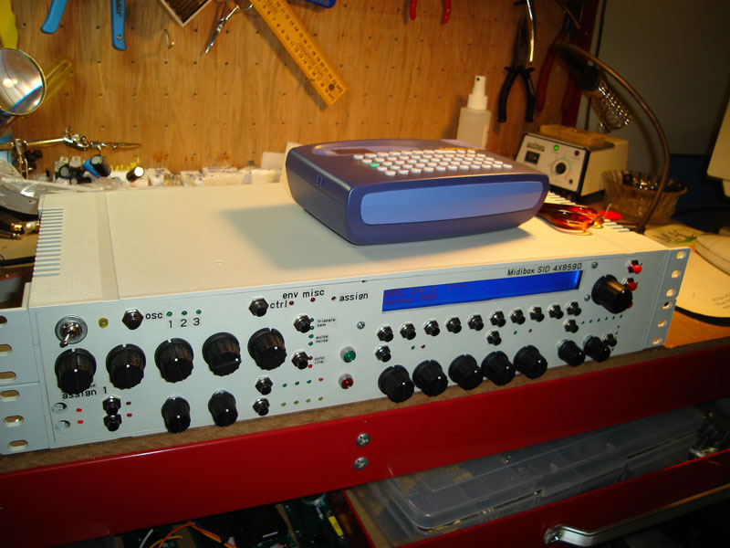
Hi everyone, Here are some pictures showing the progress of the SID synth. I think the bottom one shows how the LCD looks a lot like a C64 computer screen :) All the best, John
-
Hiya, What country do you live in? You can get some nice cases at a lot of electronics shops. Depends on what you like. I have just made one in a white plastic rack enclosure and it fits nice. If your going to make your panel yourself I could offer a few tips from my recent experience, but if you want a really pro looking one you should get our your wallet and go to front panel express. There are SID case designs for FPE ready to go. I have several variations for more simple ones I have designed too if you would like them. All the best, John
-
Hiya ultra, Welcome to the start of the process that will bring you the best sequencer in the world!! Firstly, dont take my advice as the best answer, there are a lot of people on this forum, and some are VERY good at building these devices!! Theres always a better answer!! Dont be too stressed about all of the interconnections as its not as hard as it sounds. The basic rule is to download all of the PDF files from the main site and follow them no matter what. The newer model smash boards look different but follow the same pinning as the PDF files. Any changes are listed on smashes site. His site is also a good thing to have in front of you while building his boards. With the LCD cable I have made a few and have found that if you put a female DIL connector on the core and on the back of the screen and make a ribbon cable 1:1 between them (dont worry that your connection may not be 1:1) then you cut the ribbon in the middle and label each lead (follow the lead to its source to find the label) and re join them so they all match up again. I suggest when soldering ribbon cable to ribbon cable to tin the ends and make small hooks that then join each other an to put heat shrink seal over the join. This has proved to be the best connection for me so far. This technique is only really for the 40x2 lcds as I have found the pinning never matches the core. If your pinning of the screen matches the core then disregard this. With ribbon cables you dont need to order them. Just buy some wide ribbon and the right dil connectors and do it in a vice, its much cheaper that way. Another good tip is to build it all out on a table before putting it into any case. This will make sure it works and give you a good idea of the case size etc needed. Also, its not the best way to do it, but you can solder the ribbon directly to the pins if you dont want to buy/make the connections. This is actually handy for some connections anyway when a DIL has to go to 2 seperate SIL rows ie core J8 and J9 go to Dout and Din from one DIL set. Of course there are other better ways to do this too. Another tip is on the smash boards, there may be a DIL there but only connection names on one side. Unelss you have checked that the connection is joined on the PCB with your multimeter only use the labeled pins. An example of this is on the Din boards. I have a DIL connection and was trying to use the 2 end pins as VS thinking they were joined, they arent! Yes that is correct. Another thing is that if you are soldering to the pins, join the VS earth one first as its always on one end (use multimeter to make sure its the right one back to its source) then work away from the VS cable by cable as they seem to be mostly in the same order. This way you dont need to check which is which as often (only when there is a problem). Maybe I shouldnt share too many lazy type habbits like this tho :) This one is mostly for when connecting boards from mikes shop as there is no label. J9 core goes to J1 din. Connect each labeled pin to the matching one on the din or dout. 1 row is for the din one for the dout. The DIL header on the core is labeled J8 J9 in the right order. On the din board the 10 pin connections are to go to the buttons and encoders. 8 per set are actually used, one is earth (vs) and one connects to nothing. When using these 10 pin connections you can make yourself a diagram so you can count the ribbon cables (I have the red cable on one end matching the DIL header) and write (after testing with a multimeter) what they connect to for easy reference ie ribbon 1 -> D0 2 -> D1 etc (that might not be the actual connection, check yourself). I think you will need a lot more cables than this to complete the sequencer. Have a look at the pdf files to check, you need connections to the core for each board, also you need connections from each din/dout to buttons, encoders, leds etc. These all are called shift registers (SR) and each IC chip is one SR. Each SR has 10 pins on the smash version and 8 of those 10 go to buttons or encoders. Buttons take 1 pin, encoders take 2 pins. You can download the PDFs that show the din/dout connections for each application. Here are the ones for the seq: http://www.ucapps.de/midibox_seq/mbseq_din_v2.pdf http://www.ucapps.de/midibox_seq/mbseq_dout_v2.pdf Also with the Aout, if you want to have 8 channels of the CV/Gate buy the Aout not the Aout LC board. You will have to find all the parts yourself, but the only ones that are harder to get are the Maxic 525 chips and the little shunt that goes on the bottom. You can order samples from maxic for these chips if you cant find a dealer who can sell them to you. If you want a V3 seq you should put in at least 1 IIC board now, and I would also consider an 8 chip bankstick board, and an LTC module to get the most out of it. With the wiki I dont think there is a manual showing a step by step instruction. I have had almost every imaginable problem finishing mine, so I will try my best to chip in and help you out when I can. A quick troubleshooting guide when hooking up something and it doesnt work: 0) Always plan what you are going to do first, measure things, think about them before doing them and make sure you have all the tools and infomration to do it first. This is especially true for the case, and also for the electronics. 1) Always read the PDF first, look at it, think about it, look at it again, then pick up the soldering iron. 2) Always check the test voltages before putting IC's in. This is clearly stated on the main ucapps site for each module what the voltages would be. 3) Test for connections being set up correct, use multimeter to beep out end to end. Refer to PDF to figure out what goes to what. 4) Check if all IC's are orientated the right way 5) Swap IC's on the DIN/Dout if all else fails (these IC's seem to fail a lot I have found??) I hope this has been of some help for you. All the best, John
-
HAHAH!! I have to laugh at myself... ;D It was working only the link button wasnt pressed...
-
Hi All, To add some more info to my last post in hope of hunting the problem down that SID2 is not making any sound: Sid 2 measures all the right voltages on IC1 IC2 and IC3 as shown on the main site. Sid 2 makes sound when connected to the master core instead of core2 where it is usually connected (sid 2 of 2 at the moment, waiting to get boards 3 and 4 for the sid and cores) The screen when plugged into Core 2 (slave) says CS not enabled (as I guess it should) Core 2 has a pic with ID 01 and the normal 8580 setup file in it (master core has a custom setup file) The following connection exists between core 1 (master) and core 2 (slave) J11 Vs -> J11 Vs and J11 M0 (core master) to J11 M1 (slave). J11 on the master core also uses the same pins to go to the LTC and they are physically soldered onto the same posts. The 2200uf 16V cap is on + - of core 2 (slave) I have made 2 sid->core interconnection cables and both work when conntected between core 1 and sid 1 so the cable connections are fine. Sid 2 is getting its 14V in and 5V from the core fine. I do have the audio jack for SID2 plugged into the speakers and have pressed the SID 2 button and set its cfg to midi ch2 and sent midi notes from logic to ch2. When doing all the same to ch1 (master) everything works ok (with cable in out 1). I have no optocoupler on core 2 (slave) nor regulators on either core (but bridged them as shown - thanks Wilba for the tip!) Could the problem be core 2? If so what on core 2? SW? HW? Thanks in advance!! John
-
Hi All, So far its all going well, except that I cant get any sound out of SID2. I now have the DIN and have set sid 2 to a sound and put it on midi channel 2 and plugged the audio cable in but nothing is happening. I can hear the normal pop through the speakers when its turned on and off. Plugging an LCD into the core reveals that it seems ok and functioning. I have not mounted the octocoupler on sid2s core. I did set it to a unique ID with the change ID application from another core module. The SID interconnection test shows pin 01 on the screen. Any ideas on what can be causing this? Thanks in advance!! John
-
HAHAHAH ;D Im downloading the new version now to test, also TK will I need to apply the patch you made for the seq output clock or is it inc? Thanks, John
-
Hiya TK, Sorry, I think I might not have been clear about what I meant. I agree having too many settings would be too slow and not needed anyway, but what I was trying to say is that the Kurzweil system impelemts a very simple and easy to use mixermap which includes which program is on each channel & the volume and pan of each chanel. I like how you have expanded this to provide come CC information too. Would this cc setup also the the same as the CCs in the event menu? It would be great if they were different as then the CCs in the mixermap would be the initial controllers and in the event would be continually changing controllers, this would allow for a nice usage of an encoder driven editor like MB64 when merge is turned on as the initial CC value would already be there for you. If the mixermap was pattern based then perhaps each track would have its 4 ccs stored too rather than 4 per song?? Maybe I read this wrong?? With the bankstick I just meant that I would be prepared to loose 1 of the 8 IC's for this function without any problem if needed! 128 patterns per chip and 1 chip for songs is still a lot of memory, esp when hot swapable! If giving the chip up is not needed thats even better :) Would this force the user to manually send them or once turned on would it become automatic in song playback? I like all of the implementation ideas in your list, but I thought that this one May cause some problems. Im imagining jamming with the seq in pattern mode (stryd_one style) and changing all the program numbers to test out other sounds, but then loosing my original settings while experimenting with the changes. Personally I would prefer to have to press save for something to be saved. I can see how not pressing the button makes for a cleaner work flow but it can also lead to experimentations becoming permanant. If a mixermap is associated with a pattern instead of a song, it will be implicitly included in the song by pattern use and would lead to a more flexible use of prorgam/port changes in my opinion. Also in event mode, one set of parameters for me is note cc cc cc with fixed length and vel. I might have mentioned this before, it would be a good one to have! Maybe it was in the last update, I was too busy pressing random over and over to notice :) hehehe Also on that note, the random function is great, but I think it would be nice if it did not have to choose the steps to turn on/off ie to randomise already turned on notes, but maybe to have an alternate function of random note selection and all other values as it does now? I like its behaviour as is, this would just be an alternate usage suggestion. Another thing that I think would be cool to implement if it made sense to do so and other people would use it... When I write drums with the seq I often find myself wanting to turn on a note, then set its number, then press another step and have that same number and velocity used there too by default until I manually choose another note number. ie write all bass drums, then write all snare drums, then hh etc. Using all doesnt quite do what I want as I may use one track for several drums. I know you mentioned a drum track being included? Maybe this could be a part of its usage? I never used V2 drum mode as my SEQ was not around for long in V2 and the drum mode looked very confusing to me (I didnt really try hard with it tho). All the best, John
-
I often use pattern mode only too, it would be nice to see this feature in pattern mode somehow??
-
Well apart from (to my friends continual amusement!! ;D hehehehe ) getting smacked in the face with long planks of wood, metal sheets and bits of plastic I found it to be less accurate, even when clamped and you use the punch tool to mark centre etc. Also on my drill press changing speed isnt easy, so I ofen drill at the wrong speed thinking it will be ok and crack plastic sheets!! With the hand drill I found it easier to get closer to the centre of the markings I made before hand. Cheers, John
-
Wow thats a great idea!! I was actually going to ask for a similar concept, but as per usual you were 100% on target :) I think having an inital cc value for each stored event would be great too!! Of course I would be very pleased to see song chaining used too, but thats a different feature, but it would tie in nice as you could have all these settings change on the fly as a snapshot of settings per song. I really like that you have the port setting stored there too, this is much more sensible and will allow for people with 4 IIC's to pick 16 channels out of their 64 in each song, hence making for much greater possibilities of changing configurations on the fly. I know I rave on about Kurzweils too much on this forum, but they have implemented their mixer maps very well on the K2* series of synths, worth a look for inspiration as they address the same problem you are now. Their song mode allows storage of what program number is used, volume, balance and some other settings (not to copy, but to see how its used). Perhaps a bankstick could be dedicated to this task to allow for storage of more settings too?? What would pepole who jam in pattern mode only do in this case if the settings are stored in the song? Would the patterns be independant of program changes and cc snapshots? There could be a good and bad side to patterns not using the same system. I have not had a chance to test your patch for the seq so far, sorry! Ive been too busy with the new SID. I will let you know when I test it in the next few days tho!!
-
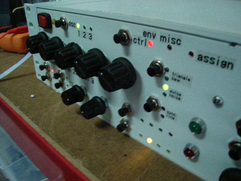
Thanks stryd_one, For the record it was all done with a cordless power drill, a very small file and a hacksaw. I do have a drill press, but I chose not to use it after my last efforts with it :) I have a special drill bit which helps where there is a drill mechanism on the end, and a grinding mechanism further down the shaft. What I think helps a lot is to print out a 1:1 scaled version of your panel horizontally flipped, tape the whole font panel up in clear masking tape and drill, file and hack away until you are going to cry from the tedium, then pull all of the tape off and theres your panel! In hindsight I would have also got a de burring tool before fitting all the LEDs but too late now. Im using a casio label printer to put on labels for the buttons and knobs, looks cheap but matches the rest ;) hehehe. Ideally I would have done this first and then sprayed a laquer over it before putting knobs etc onto it, but next time!! I think that making it this way is great, as I now have about $300 in my pocket that otherwise would have vanished :o Cheers, John
-
So far all that sounds right! Im hoping we can identify each specific feature if possible in time, I can do some of the work if its repetative and easy instructions can be followed?? Theres a lot of features!!! Let me know if I can help Cheers, John
-
Hiya Toneburst, I know there been a variety of answers, but to add to it I have orderd from them and the grooves are quite deep (I havent measured it but it looks like a couple mm at least), and can be filled with whatever you like. I used liquid paper to fill mine as it was easy to rub off any excess. With a steady hand you could use enamel paint. All the best, John
-
Hiya TK, Thanks for the comment, many hours of work went into it!! Most of it lines up pretty well. Saved me a few hundred dollars in font panel! I think it looks tacky, but in a good way. The interface isnt complete yet. You can put up a photo if you like, or I can send you some when its done, totally up to you. I will test out the link mode when the dins are connected up in the next few days. Thanks, John
-
One of the front.. Its VERY DIY :) Hand drilled and filed...
-
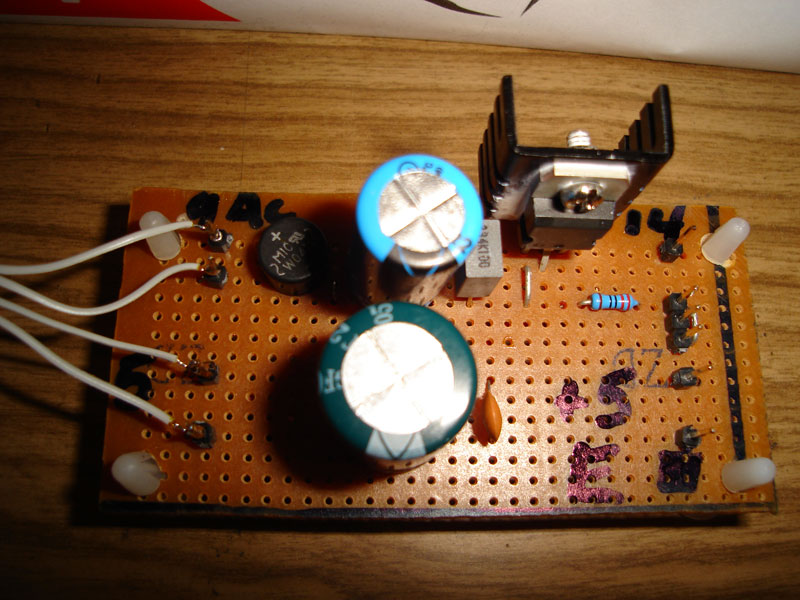
Thanks TK, The LTC is working ok physically (unlike the LTC in the seq which I still need to fix), if it can be used on J11 at the same time as the core to core link then my problem is that SID #2 is not making any sound. I dont have the DINs connected so I cant look in the menus for settings or press the sid #1, sid #2 or link buttons so maybe this is why?? I have connected up everything as shown in the 4xsid power diagram on the site. Any tips?? Also here are a few pics from the SID as it is now, ill post some more as I go. All the best, John
-
Ok, sorry for the delay, here it is! Its a dump of the master table and also the current programs loaded into it. Let me know if you need more or any help in any way!!!! Thanks, John k2000_dump.zip
-
Hi all, Can you use an LTC module in a 4x SID? I have added one to my setup (inc drilling midi in/out holes on front panel). I have the LTC working fine, but the 2nd sid (and probably the others once they are fitted) isnt making any sound. The LTC and midibox link seem to share J11. Is there any other special information to get sound out of sid 2 once its working? I have tried playing notes on midi channel 1 (SID 1 working ok) and 2 (nothing). If the LTC can not be used can I get in/out lights from the Dout instead? Thanks!! John
-
Jidis, Thats interesting the UAD 1 cards use an old CPU, must be cheap to produce. I actually have the schematics for the K2000 here as well as a lot of other documentation, I should look around and see what CPU it is, maybe it could be swapped? I dont know that it would help the update issue tho?? I did see a good site suggesting some hardware mods to a K2 that I might look into... http://members.cox.net/barryklein/k2000.htm Ive ripped mine to bits and back again a few times now and soldered to the boards so I feel like I might not kill it!! The more I look at it the more MIOS and K's are the perfect partners with the K's miriad of CC destinations (and hopefully soon a full sysex editor ;D ) Im still going to post a sysex file b4 I go to sleep tonight :) John
-
AC, when you say for PowerPC, do you know what models are supported? Will it run on my 9600/350 or G3? The G3 seems not capable of OSX as each boot it forgets all the pram settings (with fresh battery, zapped pram, and also reset open firmware). Id love to get java on an older ppc!! Thanks, John
-
HAHAAHAHAHA!! Thats ok stryd_one, I think everyone knows youve got a good tone to your messages :) I had a quiet laugh!!! Buy a K2000, there 70% as good as a K2600 and 5% of the cost. Ive got 2 of them and when you look at bang for the buck, 16 outputs, 48note polyphony, 2 multi fx engines, 128mb of ram (plus a whole wack of other options I wont even go into) all in the VAST system... You can get 2 of them for around or less than $1000 these days which is pretty decent. Jidis Im still working on getting you the sysex file, I should have it tonight, I just cant pully myself away from my new sid im building :) All the best, John PS Stryd_one, Ive been LMAO with your latest sets of footers on your messages too.. hehehe Esp the one about the search and wtfm :) As geeky as we all are its nice to see a sense of humour in all this!!