dcer10
-
Posts
346 -
Joined
-
Last visited
Content Type
Profiles
Forums
Blogs
Gallery
Everything posted by dcer10
-
Hiya, Sorry I dont think they are the type you are looking for. The ones I have which are dead are mostly this one: http://home.iprimus.com.au/king_willy/kw64/graphics/mine/c64pow.jpg Its odd in that the 9v AC is actually 3-4v DC on the problem ones.. Thats before it even gets to the board! They can be taken apart easy so I think repairs could happen. Does anyone know the type of transformer used? I also have a couple which are for the disk drives too, the beige sealed ones. Unfortunantly none with the plugs you want, sorry! Does this help you?? http://staff.washington.edu/rrcc/cbm/plus4con.txt Thanks! John
-
Hi All, Ive got myself 5 dead black commodore 64 external power supplies, which all seem to be dead. They all have a similar fault in that the 5v works on most on them, but the 9v is low (around 3-4v). Does anyone know any common repair methods? Is it easy to replace the actual transformer? If so what spec would it be? Thanks!! John
-
Hi All, Im sorry if this has been asked before (couldnt find the info), but will I need to swap all of the pics over to 4620's or just the master? Also has there been any consideration to add amplitude modulation to allow AM synthesis? Is there a pre release version of the software TK? Im getting my hardware setup to allow for an upgrade without opening the case later, it would be nice to test it out. All the best!! John
-
Hiya, im very interested in that. Is there a way to make use of the data extracted from them? I want to be able to take midi files from them if possible??? Guess a sequencer emulator might be needed? Cheers, John
-
Just a thought, you could use the stacking method for your setup as you dont need to mount the big cap on the core module, so the stacks could sit side by side easily. Also another thing you can do for the SID cap is to place it else where in the case and run wires back to the pcb from it. I have a big cap sitting off board which is hot glued to the bottom of the case and it works fine. All the best, John
-
Hiya Stryd_One, I tried putting DOUT_ENTRY CS_MENU_SELECTED_OSC_FLAGS, 1, 6, 3 ; OSC2 LED into the application code but it still isnt working. Any other ideas? All the best, John
-
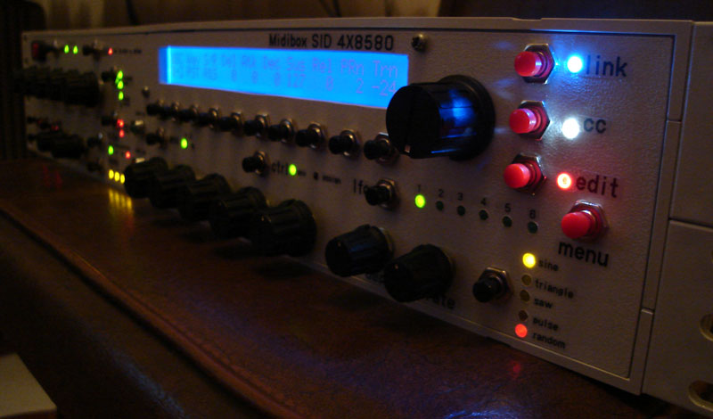
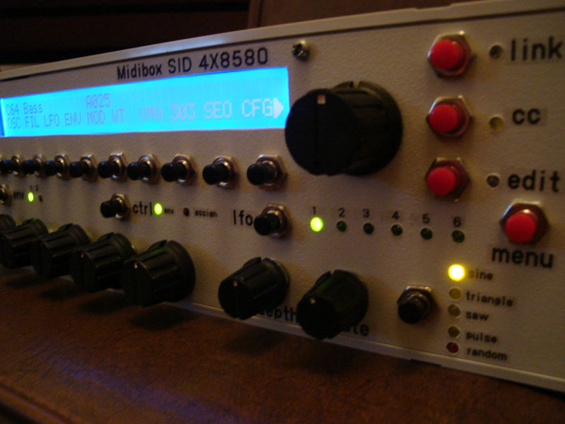
Hi All, I thought I'd upload a small basic example showing the use of 2 SIDs as a stereo filterbank module. There isnt any external effect on the sound it is simply a TX81Z on an otherwise pretty dull sound being triggered from the MB sequecer using 2 tracks for the SIDS to alternate vol 0-127 on each step to flicker from L-R and the filter on the SID using BP + HP with a synced LFO and unsynced LFO to modulate the filter frequency [and a drumstation for good measure]. Its a pretty basic example im just trying to encourage people not block off the audio inputs unless they know what they are missing out on ;D a 4xSID is also a very good 4 channel midi filter bank with LFOs!! Its noisy, but since when do people who use 4 channel filter banks care about noise ;) Im making up a bank of "filter only" patches and im willing to share if people are interested when its done. I guess there not hard for people to do themselves, but something to get people going quickly might be a good thing?? All the best, John stereo filter example.mp3
-
Sorry to repeat myself, but this is freakin fantastic!!! Ive been spending most of my free time tonight to re set up my whole studio based around the SEQ now, esp with this mixermap section... Its working very well. All program changes, ccs etc all getting where they need to!! Awesome work TK!!! Just goes to show that sometimes the most fancy solution isnt the most impressive feature, this feature makes this a whole new machine in my view. All its lacking is the ability to chain songs ;D All the best, John
-
Wow that is so tidy!! I love it!!! Great choice of colours. All the best, John
-
Dont worry Stryd_one, your V2 Sid will not leave you wanting!! It will all be worth it in the end. Just set up all the audio side of my studio again, its all been a bit of a mess while ive been out soldering all the time! Heres a VERY basic test using only 1 SID, a TR-909 and the MB Sequencer that I sampled. It goes to show that the SID can be a very good 303 emulator if wanted, and that the MB seq is its perfect partner for acid basslines :) The resonant filter is actually a lot better than people give it credit for. Warning.. Acid basslines following.... Also a short clip on youtube.. No sounds tho. TBSID1.mp3
-
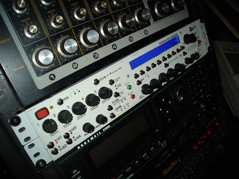
Thanks m8! No, its not an AX73, but close! Its an X7000, not quite as interesting :) After a second look at my own pics I have to say Stryd_one, you have very good eyes!! I could hardly make out where the Akai was!! Hehehe Ill try the change tonight, I hope it works! Amazing how many little tid bits like this you need to know to customise MB's!! Im glad you seem to know most of them ;D All the best, John
-
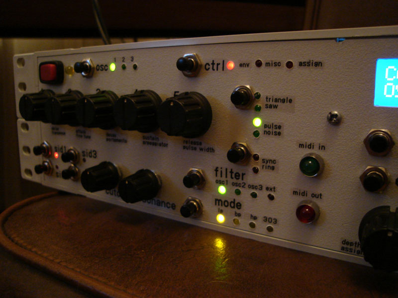
Ok, one small detail that is still haunting me that im hoping someone can help me fix. The OSC 2 led isnt working for whatever reason, it didnt work using the default pin for the Dout and I tested with another LED on that pin and it didnt work, so I thought it was the cable so I just got a cable from another unused pin. I chose SR 6 pin 4. I thought from my counting that OS2 was on SR 2 pin 6 to begin with (0x0e) this is also what is shown in the PDF. In cs_menu_io_tables it says that osc 2 LED is: DOUT_ENTRY CS_MENU_SELECTED_OSC_FLAGS, 1, 2, 1 ; OSC2 LED I take that as SR 2 pin 1? Anyway, the one which I want to change it to is SR 6 pin 4 (0x2c) so I changed this line to DOUT_ENTRY CS_MENU_SELECTED_OSC_FLAGS, 1, 6, 4 ; OSC2 LED But it wont work. Considering that 2,1 is not what I expected to see here in the first place I guess that im reading this wrong. Can someone point the solution out please? Thanks, John
-
SEQ V2->V3 Migration inc older V2 problems in post too.
dcer10 replied to dcer10's topic in MIDIbox SEQ
Thanks for the reply TK, it is working now, mis configuration on my part :) Sorry to take up your time! All the best, John -
.
-
.
-
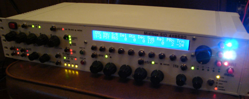
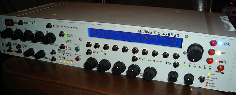
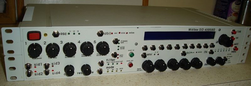
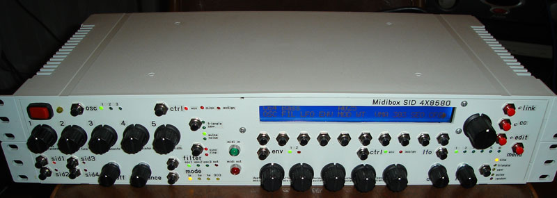
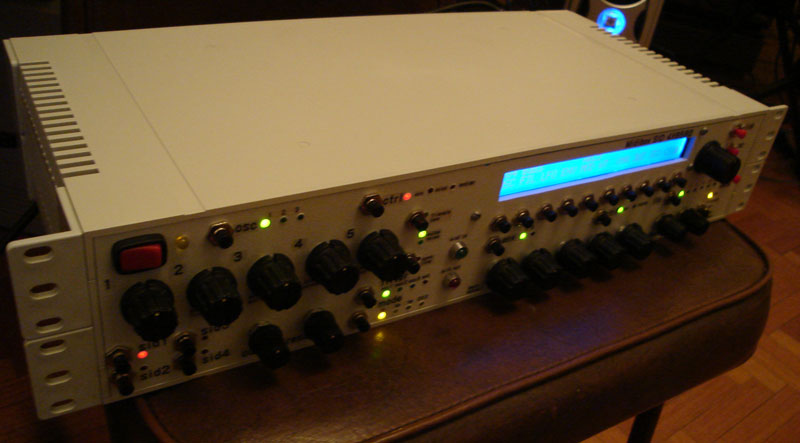
Well this stage is finished, I just need to wait now for my new sid boards and core boards, but the 2 SIDs in there and the CS are all working (except one little annoying thing with OSC2 LED). Heres some final photos of the case. All the best, John
-
Not really MB related, but I also saw this link: http://www.floodgap.com/retrobits/ckb/secret/ Which is awesome if you like the history of the commodore. All the best, John
-
Woohoo!! I think I was right as its working now!! 250ma fuses blow and 500ma dont (got one more dout board to wire up, 2 more sids and 2 more cores so I hope the 500ma will hold!!). An important lesson for me here is not to use the black C64 Power bricks as they dont have a fuse and blow. The beige ones have a fuse and dont die as easy. I might take some photos of the various ones as I have at least 4 kinds and only 1 kind has been good to me :) Thanks, John
-
Hi All, I have a theory (which is probably wrong!) that the load in my sid had exceeded 250ma, there was a 250ma fuse in the C64 PSU (Ive read the psu does 1amp??) which blew either when shorted on the power input, or perhaps as I was testing the Douts? I kept adding new LEDs to the dout, then testing, this is when the whole thing went pear shaped.. Im going to hunt down a bigger fuse, maybe 500ma?? and see what happens. <optimism>Maybe its not even damaged? </optimism> Will post my results. Cheers, John
-
Hi All, Ive been having some trouble with my SID and its PSU (not the board, the actual PSU brick) and I came across this article on the web which I found interesting and thought others might like to read it. It shows how to test out the PSU (they actually use a very odd way to do it I think, use a multimeter instead!!). Its also got some other info about the PSU that might be interesting background reading (or not) :) http://personalpages.tds.net/~rcarlsen/cbm/pstester.txt All the best, John
-
Some tools you will need/want: A nibbler tool (check at your local electronics shop), see that the depth of the panel does not exceed the opening at the tip of the nibbler. Deburring tool Hand drill with various drill bits esp 3mm (lefs) 7mm (encoder shafts) 5mm (some buttons) Router drill bit (drill at tip, file at base) Hand files (various sizes and shapes) A hacksaw blade (not in the hacksaw - use thick gloves when cutting with it, its good roughly cutting out the screen) FPE software (to make your own design, print to PDF using bullzip or your fav PDF creator, flip horizontal in photoshop, print, merge sheets of paper, glue to back of panel and drill into) Centre punch tool Square ruler Marker A dead screen of the same size as the ones you want to use (to drill mounting holes without killing the screen) A hot glue gun I have just (almost) finished a 2 RU case you can see in this post: http://www.midibox.org/forum/index.php?topic=8033.0 As the photos show, its all panel mount, not a single circut in sight of the panel. The downside is, a lot of wires!! It does save money and time on the PCB's for the buttons etc. Im not saying its the best way, but it works! All the best, John
-
Ive just had a free minute to test out the new version, I think the way the mixer is implemented seems great! Im a little confused as to which has preference for ch and out ie mixer or event menu?? Didnt get too long to play with it yet. Also are the two cc's freely assignable? If it is set that they are 91 and 93 by default then I see how to do it (didnt have time for a full test). Im really looking forward to spending some time exploring this new section in the seq, I really think this is the biggest enhancement so far!! A quick observation, I'm not certain I'm set up right, but it seems that I can not get the program changes to come out to IIC2,3 or 4 but IIC1 is ok. Actually on IIC1 it is great, it jumps to my user bank on the K2000 (200s) without any fiddling about at all. Some expensive software sequencers have a hard time doing this without playing about with it a lot on the Kurzweil... Well done!! Im hoping that I can send to the other ports too as easily to my other gear. I tried to use the port mixer page and ch mixer page and set them all to the same as in event mode, no luck tho. Dave, I guess you probably have, but just in case, have you tried assigning a track to Note cc cc, defining the CC to what you want to control then going to the cc value layer and pressing all? It basically will allow realtime controls. It seems to only work when you retrigger a note tho to change the cc value. Pretty handy tho!! I looked in this new version and that modification seems to have already been made so I will test it out with the kurzweil sequencer shortly and post my results. I can see why!! Esp for CCs. Thanks TK!!! ;D
-
Hi all, Now ive done it, I think I shorted the main in for power and heard a little zap (it contacted with the inside shelf in the case when fitting) and blew a fuse in the C64 PSU. I replaced the PSU (didnt have a fuse) and now im getting -0.53v where I used to get 5v on the 5v rail of the 4xsid psu. The 14 v is doing just under 9v. Any ideas which part might be ruined? Thanks, J
-
SEQ V2->V3 Migration inc older V2 problems in post too.
dcer10 replied to dcer10's topic in MIDIbox SEQ
Hi All, Is there any reason why the seq might have trouble sending midi properly to the SID? I can see that the signal is getting to the sid as the lights on the LTC are showing midi in (and the lights on IIC4 in the seq show midi out) but the sid wont respond. When using a compter to trigger the sid it works fine. Also other gear on IIC4 of the seq works fine too. Is this a device ID problem? Thanks, John -
last one in this bunch...