Wisefire
-
Posts
416 -
Joined
-
Last visited
-
Days Won
1
Wisefire's Achievements
MIDIbox Tweaker (3/4)
1
Reputation
-
i am just stupid, that's what the issue was, or more like i was a bit conceited. thought i could pick up where i left off and have all my knowledge intact.. i FORGOT to upload the MIOS hex first.... yep, that IS dumb.. alright. so now, i'm facing other issues. i keep getting errors when uploading mios to some of my pics. i got just one of my 18f452 pics to accept mios. cool, so i have 1 pic that should work. but when i plug the mb_core into the header of the relay board, only 7 relays are working. not 8. so pin testing time, only 7 of the 8 pins output 5V. weird. bad PIC? alright, lets try my hand at programming the bootloader on one of my virgin 18f352, pickit3. nope. borrowed pickit2. nope.. oh hey an old 18f4685 in my stash, with bootloader!!! alright lets upload mios to that one.. success!!! buuuuut... only 7 of the 8 pins outputs 5V. WTF??? possible causes. issue: 1 relay doesnt switch. Could it be a faulty relay? - no, inverting the sil socket cable, moves the issue to another relay. Faulty cable? - could be, but testing directly on the mb_core shows that that specific pin wont give 5v. bad pic then? - maybe, but 2 different types of pic have the same issue on the same pin. Bad mb core PCB? - no, tried multiple, besides i've measured continuity. Bad source code - i'm not willing to believe TK wrote it incorrectly and didn't tested it, but for a learning experience let me see if i can check it with my limited knowledge.... nope it's mostly in assembly as far as i can tell. got as far as the function J5_IO_PinSet which can be found in the j5_io.inc file. dope, but it has more than 8 pins listed there, but it seems to forward those pins to the other pins if certain conditions are met. pin numbers seem to be in WREG, couldnt find that though. and even then, i wouldnt know what to do with it. TL;DR - found a solution for the problem in my previous post (i was dumb), new issue, pin a0 on j5 won't output 5v after booting like the other pins, and doesn't react when sending C4 to the MB_core, the other pins work like expected.
-
After coming back to this issue every once in a while (real life stuff keeps popping up) it just occurred to me that I was most likely using older pic processor back then. in the mean time i've ordered a pickit from ali. Once I find a bit of time, i'll go through my older pic processors to see if I still have an older one. and see if i'm able to program it with the bootloader.
-
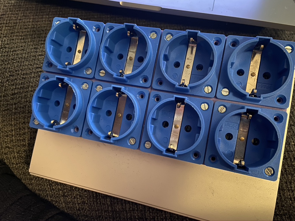
I do hope nobody minds me resurrecting this ancient thread. I finally started on that 8 out relay thing (9 years, damn!) i've mostly got the hardware built. But i've been halted by bit of an issue. i've uploaded the j5_dout example hex to my core8, but the core8 doesn't seem to react to the midi note c4->c5 that i send it through mios studio. i've tried measuring it with my multimeter, and an oscilloscope, but only got 0v on the pins. the core announces itself dutifully through Mios Studio, so i know the core is working. I've got multiple cores lying around, so i tried it with another one as well. What am i missing? ps. sorry for the lack of pictures, as a meagre solace, here is the one i'm currently building.

-
i might be interested. still available?
-
ik heb besloten de backlog eerst maar eens af te maken, voor zover ze nog relevant zijn. en te kijken naar wat ik werkelijk nodig heb (maar het is allemaal zo mooi :P )
-
@NLX, hahah, heel herkenbaar idd. ik heb dozen vol met onafgemaakte projectjes, maar mijn MB_SID is toch wel de main one. die moet nou eindelijk 'ns af. :P @shruriken no worries, sowieso tof dat er zo'n community spirit leeft.
-
hey NLX! thnx voor de tip! Electruck heeft me er mee geholpen, maar wel leuk om te horen dat er nog steeds actieve nederlandse midiboxers zijn. :D
-
You can connect what you want for your CS, i've used it without any cs in the past!
-
Alright, another update is due. While waiting on some other things to arrive (PICs and CS pcb) i thought it was a good idea to finish some other projects. So i removed some detents from encoders and I received 25 lego pegs, dremeled them in two, glued them on tactswitches, some more dremeling and put on my custom rubber caps. And today i visited a good friend with a lasercutter. And cut out the frontpanel out of triplex wood. Sanded it down and put on somespray laquer, this is the result.
-
YEEH! Most of my Mouser order just came in. Tact switches, which i will modify. Dual potmeters for the feedback. Some bolts, nuts and spacers. And a lot of diodes. now its only waiting on the PACTEC PT-10 case. as for progress: The rubber buttons i want to use on top of the tactswitched are too big. so i needed to find a solution. and i think i found one. on top of the tactswitches fits, exactly fits, a lego connector peg. and the rubber buttons fit exactly on top of these. i've ordered 25 of them. i'm going to cut them in half and hopefully stay under 15 mm in total, otherwise they'll sticks out too much. In other news, I succesfully ordered a CS from SmashTV. I love how he provides some excellent service. and i'm a real stickler for service. CS en BASE boards usually go together. and smash just sold his last pair. new orders would come in about 3 weeks and he could order one CS extra for me. however this would mess with my plan to have this thing done in time for a performance i'm planning to do with it. So smash came up with another solution, he remembered that he had one bad CS board in his discard pile. it had one bad trace and usually wouldnt sell these at all. but instead of him throwing it away, i could throw it away for him :P long story short, i'll have a near mint (IMHO) CS board for a significant discount AND in time for me to complete the project in time. the guy is golden! thats it for now. till next time! thats it for now
-
Hey Roel, Bedankt voor je aanbod! Opsturen is te doen, maar mocht er een midiboxer in amsterdam wonen is dat uiteraard makkelijker. Mocht ik na t weekend geen verdere replies krijgen dan zal ik je ff pm'en voor de details.
-
Hoi, is er iemand in de buurt van amsterdam die toevallig die een PIC18F4685 kan branden? groetjes, Ysbrand
-
alright, i've thought about it some more. I'm going for a wilba design, with some minor alterations. which are mostly frontpanel related. His design is very good, and combined with the ease of construction it makes it the better choice. I've ordered the following from mouser: 4x 100K AUDIO POTMETERS (for the feeding the out back into the in of the SID) Some screws, washers, and spacers. 100x 7.0 mm high 100gf buttons. which i will use with custom caps. (ordering a 100 is cheaper than ordering 50, weird) 100x Diodes 1x pactec pt-10 production unit, which is only 14 euro! it doesnt have panels, but i dont need those! this means i would only need a CS PCB from SmashTV (i haven't heard back yet, i'm guessing he is enjoying the holidays and has taken some time off.) which hopefully will fit inside an envelope and means cheaper shipping i hope. and i would need a front/backpanel. i have a preliminary design for the frontpanel and will be easy to get lasercut out of plastic. for the backpanel i couldnt find a DXF file, i've contacted wilba for a frontpanel file with mountingholes, so i can have the choice to mount the spacers without jbweld (afaik, we dont have that in holland). When i get a reply i'll ask him about a DXF file for the backpanel as well. and finally a question. i'm going for the feedback option, and im wondering if the [EXT IN] button near the filter is switching only the audio in, on or off. or is it doing something more? If its only to switch external (or feebacked) audio on/off, i could rename it to feeback, change it in the software as well, would look nicer imho.
-
Hey Shuriken, Thnx for your input. And you are absolutely right. After some soul searching (or rather rationally evaluating the pros and cons) i've come to the same conclusion. It helps to have my conclusions externally confirmed though. There are some slight alterations i'm going to make, for which i won't need to go out of my way to achieve them. i'll put a blogpost up soon explaining my thought process.
-
Alright, i'm stuck within choices. When i started about 8 years ago (i had to look that up, see here for my old blog.. has it really been that long?) there was only a sidV1 and no mb6582 from wilba. I collected parts to be used in a compete CS, all diy wiring, as that was the only option. Then came the V2 and wilbas awesome mb6582 project with it. I got his base pcb, as i still had my own CS in my head. Fast forward to now. I'm finally at a point in my life where i can finish this project, as i want this to be done, and start using it. Especially because i've found one of the dutch chiptune communities, eindbaas. Back to the choice i now face. Do i really want to build my own CS? Pros are: Customized to my liking. Able to use my old stuff i've collected. Rackmountable if i so desire. Cheapest solution (excluding my time) Mono outs. Or do i want to go with wilbas design Pros: Beautiful design. Pro looking insides. Less troubleshooting. Faster to build. Here are some pics of the stuff i have: First an overview. Jacks. Datawheel. Encoders and knobs. Buttons. 2x40 and 4x20 Lcds, and row of buttons for the 2x40. Red leds and ribbon cable. For me, the most important factors are, usability/functionality, cost, and time spent. It would probably take me 2 months to design and build my own CS. Excluding any difficult troubleshooting. I may also fail completely. What would it cost to go for wilbas design? I would need: A CS pcb. From smashTV. - unknown Maybe A lot of buttons. - not much i guess. A lot of diodes. - not much i think. A pactec pt-10 - 25 euros A frontplate - free (i know a guy.) If i can change the buttons on his design, i may be able to use my the ones i have. Or make the holes bigger and use these. I'll contact smash for an estimate, so i can make an informed decision.