carsten_the_dane
-
Posts
176 -
Joined
-
Last visited
Never
Content Type
Profiles
Forums
Blogs
Gallery
Everything posted by carsten_the_dane
-
mbsid no sound. all test passes
carsten_the_dane replied to carsten_the_dane's topic in Testing/Troubleshooting
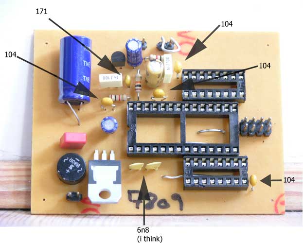
Quoting Modularcomplex: On your board you have marked a cap with 171. This should be 471 (470 pF). The two white foil-caps you used making me wonder. Are these really 1nF? My bad about the 171/471 thing, it was hard to read. It is infact a 471. The white foil-caps says: 1n J 100 - i bought them from Mikes electronik seite (it wouldnt happen to be you?), and i really had my doubt about these, but they were the only ones adding up remotely. About the PSU. i though i had one line feeding 9V AC connected to J1, and another line fedding 5V DC connected to J2. Maybe i constructed my PSU wrong. I just tried testing the one line i though would give 9V AC, and it gives me 5V DC? Nice to see some other ucapps people in my threads, i was starting to feel i was using TKs expertise to much ;D /carsten -
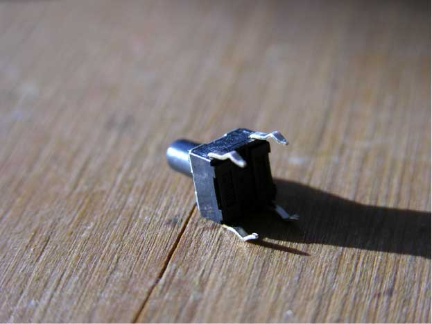
Hi I have made a nice picture of a button with 4 legs. What is what, and how do i connect it?
-
mbsid no sound. all test passes
carsten_the_dane replied to carsten_the_dane's topic in Testing/Troubleshooting
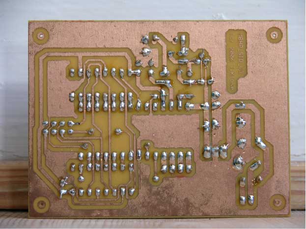
With the optimized PSU? How can it be higher than 9V before 7809, when the input is 9V. Because if you mean when testing with 15V connected to J1, then it the test passes, and that is not the problem. I send a picture with this time. The back picture will probably not tell very much (i have actually improved a lot since this. I have a new and much better iron. My Dinx4 looks good) About the front: I had my doubts about all the capacitors, but i think i made it right. Would you please have a quick look. Dont mind the audio in bridge, its just temporary. -
mbsid no sound. all test passes
carsten_the_dane replied to carsten_the_dane's topic in Testing/Troubleshooting
You´re right. The voltage drops from 5V to about 2.8 after 7809. Should i look for shorts, change the 7809, what? I dont think its a short, because i have made 3 boards at the same time, and they all show the same failure. I could post some pictures when my camera has recharged? i was sure i had gone over all measurings, but i guess i missed this one. /carsten -
Hi Im stuck. I have made the initial test to the SID module. I have: 1. uploaded the interconnection program, and all tests went fine. 2. Tried 2 different 8580. 3. tried with 2 different SID modules. 4. Made sure my "mono jack plug" is correctly installed. 5. Uploaded testtone. Now im stuck, i dont get any sound, and i dont know what to do now??? I hope some of you have a bright idea. /Carsten
-
I think the link points to a photo of the process, not a pdf. I was just reporting a broken link, my LCD works fine ;D Hurra
-
Hi The photo of connection between 2xLCD and core is missing. The link is broken: http://www.8ung.at/ucapps/midibox_gallery/axel15.jpg @ http://www.ucapps.de/mbhp_lcd.html /carsten
-
Forget about this question. I found the info. Anyway i´ve been using alot of hours these past days. But i have now uploaded MIOS and testtone but not getting sound. But i have to continue tomorrow.
-
Hi Im making progress, and now i have a new question: The MIOS bootstrap newbie site says: the Newbie method: plug the slave PIC into the master core socket and program it in the same way like you did for the master PIC. Only differences: you have to pick another .hex file, and you need to change the device ID. This has the advantage, that you can also ensure that the software is installed properly with the master core/SID as a "reference". What other hex file is that. I cant find a special SLAVE HEX??? Thanks /Carsten [edit]: hi TK could you edit the title of this topic, it is of cause slave and not slace
-
Why would i want to use SIL headers?
carsten_the_dane replied to carsten_the_dane's topic in Tips & Tricks
of cause ::) -
I´ve been thinking about these SIL headers on every J part of the modules. Why would i want them, can they come in handy later? To me it seems i would get a much better result just soldering the wire directly at the PCB. Anyone in disagreement? /carsten
-
Stuck in voltage testing
carsten_the_dane replied to carsten_the_dane's topic in Testing/Troubleshooting
Ok. So that is possible. The reason why i had my doubts was that i had a 0V reading on the sid while having the sid and core connected. (using both optimized and non optimized psu setups). I guess i must be doing something wrong with my PSU then. It would be nice to be able to check the SID before building the mbhp_sid_c64_optimized_psu, so that i would be sure that the problem wouldnt be with the SID, but the PSU. - I guess i´ll have to buy me a 15V psu. If i can find one. /carsten [EDIT]: Afternoon; just bought an adaptor with adjustable voltage. Pretty expensive, but i guess i can use it for other stuff too. I have tested all my sid modules and they all work. nice, succes. That must mean i made the PSU wrong - now i know what to do tonight (who said study) -
Stuck in voltage testing
carsten_the_dane replied to carsten_the_dane's topic in Testing/Troubleshooting
Ok. Sorry for being unspecific - i acted out of frustration :) Here is what the walkthrough says: Don't plug the SID and the two 74HC595 into the sockets before the initial voltage checks. Connect the SID to the CORE like described in one of the following schematics: mbhp_sid_c64_psu.pdf, mbhp_4xsid_c64_psu_optimized.pdf. All of them refer to the C64 PSU, but they are also informative if you are using a different PSU And here is what it says at the SID module page, at picture 2 of the soldering guide: Mount all the parts with the exception of the three ICs. Apply power to the module and check the voltage level between pin IC1:Vdd(28) and IC1:Vss(14) - it must be 12V for the 6581 SID, 9V for the 8580 SID. And at picture 3: Now connect port J2 of the SID module with port J10 of the core module like described in mbhp_sid_c64_psu.pdf So i read as im making an initial voltage measure at the sid module, before connecting the sid and core modules. But if the core and sid modules are not connected, the c64 PSU only delivers 9V to the sid module. Then the question is: Isnt it possible to test the SID module with the c64 PSU? Or in other words: How can i connect all 15V of the c64 psu to the sid module, without connecting the sid and the core. (Since no one asked this question before, im guessing im missing something obvious or im misreading the description) /Carsten -
Another evening without succes. >:( I need to know 1 thing: 1. How do i test the sid with the c64 PSU. i cant find a solution to this, but im figuring it must be possible. I have not been able to find a 15V dc psu, so i would prefer using the c64 PSU. /Carsten (PS for TK: I have just started another thread, where i accidently said; "about to test core" - could you please delete it. Sorry for the trouble)
-
Check! Thanks :) http://bionix.burningmountain.de/c64_optimized_psu_pcbtest.pdf /carsten
-
Hi I find using schematics alone a bit confusing. So i wanted to hear if there was a friendly soul who would care to make a kind of QUICKVIEW file of the "c64 optimized cpu" on a vectorboard. I tried making the "non optimized" yesterday, but i had no luck making power. Hope you can help Thanks /Carsten
-
core measure, mclr - vdd 0V
carsten_the_dane replied to carsten_the_dane's topic in Testing/Troubleshooting
Whoops, my bad. you´re not supposed to measure between mclr and vdd. Guess i had been working on the project to many hours yesterday ::) -
Hi Found a psu able to test the core. I have made 3 cores today (phew), only one giving problems 8) All measures are good except mclr - vdd which gives me 0V. I find it strange that the rest of the measurements are good... Im expecting a short, but i cant see any. Any suggestions. Also; how can vdd - vss be good when mclr - vdd isnt. /carsten
-
One final remark that you might find interesting. I burned them using the 74HCT14, if it comes up in the future. /carsten
-
WOHOO - i have burned the PICs ;D :D 8) No doubt there was a problem with mclr, earlier on, but changing t1 changed that. The problem with vdd was just me. As you can see in my earlier post, where i posted an image of where i was measuring, i thought i was supposed to measure vdd at IC3 and IC4. And now i have finally burned the pics and i am on to create more problems with the core ;D Just wanna say again that you have been a great help, and i really appreciate it. /Carsten
-
78L05: 5v 5v through the circuit down to IC3 #5 IC3 #5: 5v IC3 #10: 4,85v D2 Anode: 4,85v D2 Cathode: 4,15v [edit]: Did the regular tests this morning. And suddenly everything seems to work great. Lights toogle on and off, MCLR toggles between 12,5 and 0. clck and data between 5 and zero.... And vdd toggles between 5 and zero on pin 14 at IC3 and IC4.... ONLY, IT IS INVERTED. its zero when vdd is on, and 5 when its off ???? [Edit2]: Just tested on another machine which has a higher voltage from the lpt (about 4,something) - Here vdd just doesnt turn of, but keeps feeding 5v. Again, everything else works (though here "check data in" returned 0 and not 1) So my only problem now is VDD. /Carsten
-
I just read the sticky about "keeping your noob status" - Guess i have done everything written in that document :-X :-\ Anyway. I just want to say that i really appreciate your help, and i can perfectly understand if your starting to get a little annoyed. Now, the LEDs toogle allright, and i also get a difference in voltage which is 4,15/0. I guess thats better than nothing, but why im lagging a little under 1 volt, i dont know. (This was both with the new HCT and my "old" HC, since i havent bought the new ones yet). I guess the problem was with the transistor, which i have changed now. I know it was a little early... So i guess todays question would be: have you experienced the "toggling" working like this 4/0, and what could cause the circuit to not output 5v?
-
Ok, i have found a danish netshop who sells 74hc14. I should have them tomorrow. I do have a question though: As i understand the 74hc14 works as a trigger that affects the transistor. What i dont understand is how (according to your steps above) the circuit can go from 0 to 5 volts, without the batteries being connected. Without the batteries connected shouldnt it just switch between 0 and something low (like 1.38v). Thanks, Carsten PS: if you know where there is some documentation on the web about the mbhp_burner, could you please post a link. I have been reading about Brenner5 and picprog, but it doesnt give me much insight into whats going on in the circuit. Also i have used wikipedia as a refernce to the different components.
-
Im back ;D What part of this system amplifies the voltage from the LPT. I measure 3.3 volts directly from the LPT. and 1.38 at the cathode of D2. the vdd and the vpp can be toggled from p18. I was only able to find 74HCT14N - is this a problem, the dealer told me they had kinda taken over after 74hc14, which he told me wouldnt come back in his store again.
-
great. thanks - i will do that asap