carsten_the_dane
-
Posts
176 -
Joined
-
Last visited
Never
Content Type
Profiles
Forums
Blogs
Gallery
Everything posted by carsten_the_dane
-
mbsid no sound. all test passes
carsten_the_dane replied to carsten_the_dane's topic in Testing/Troubleshooting
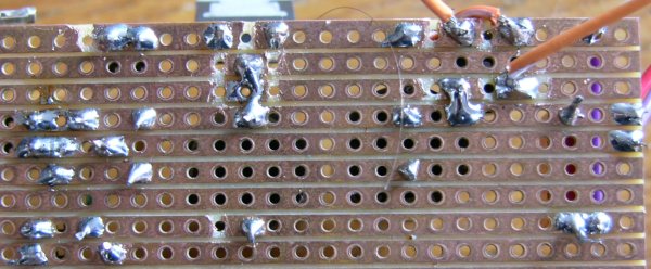
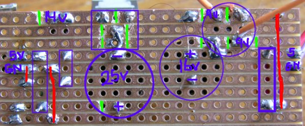
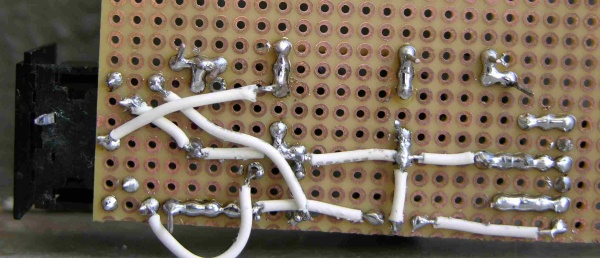
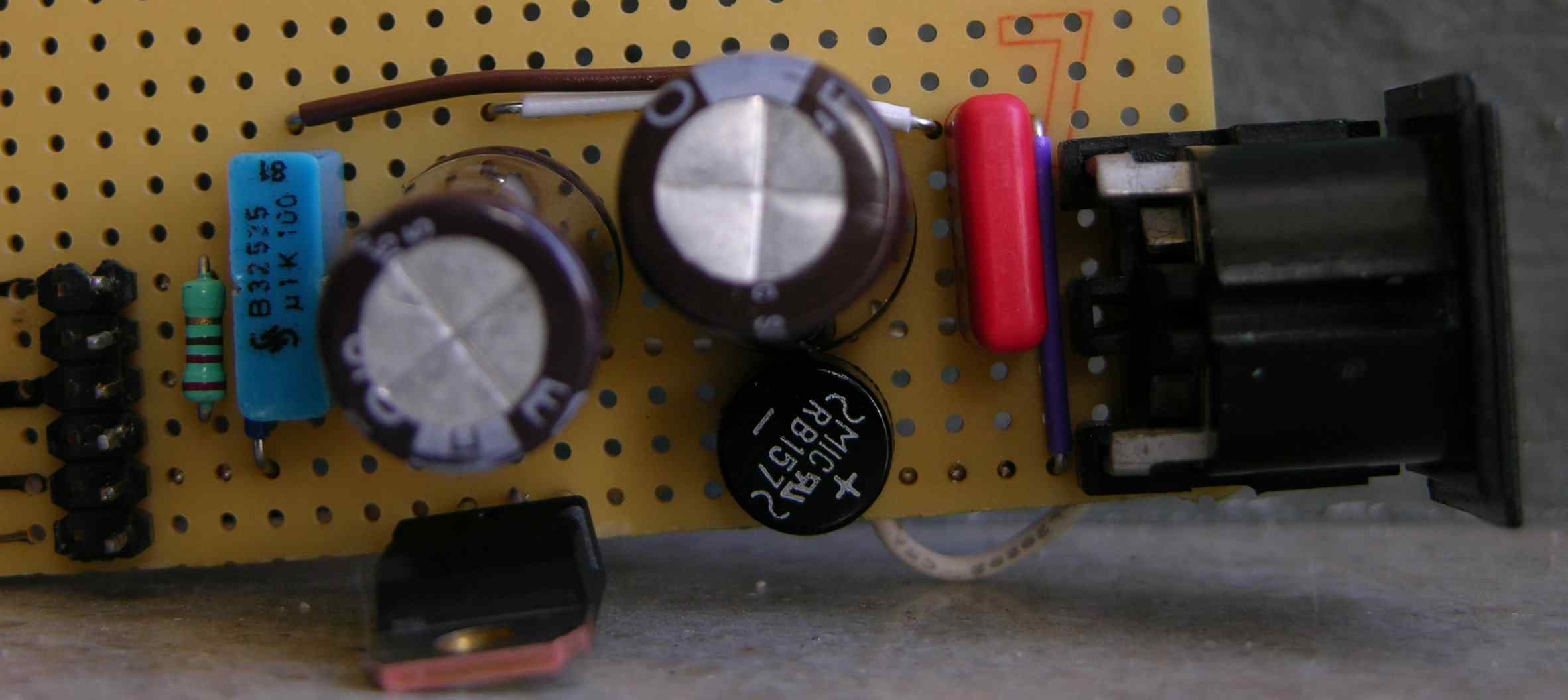
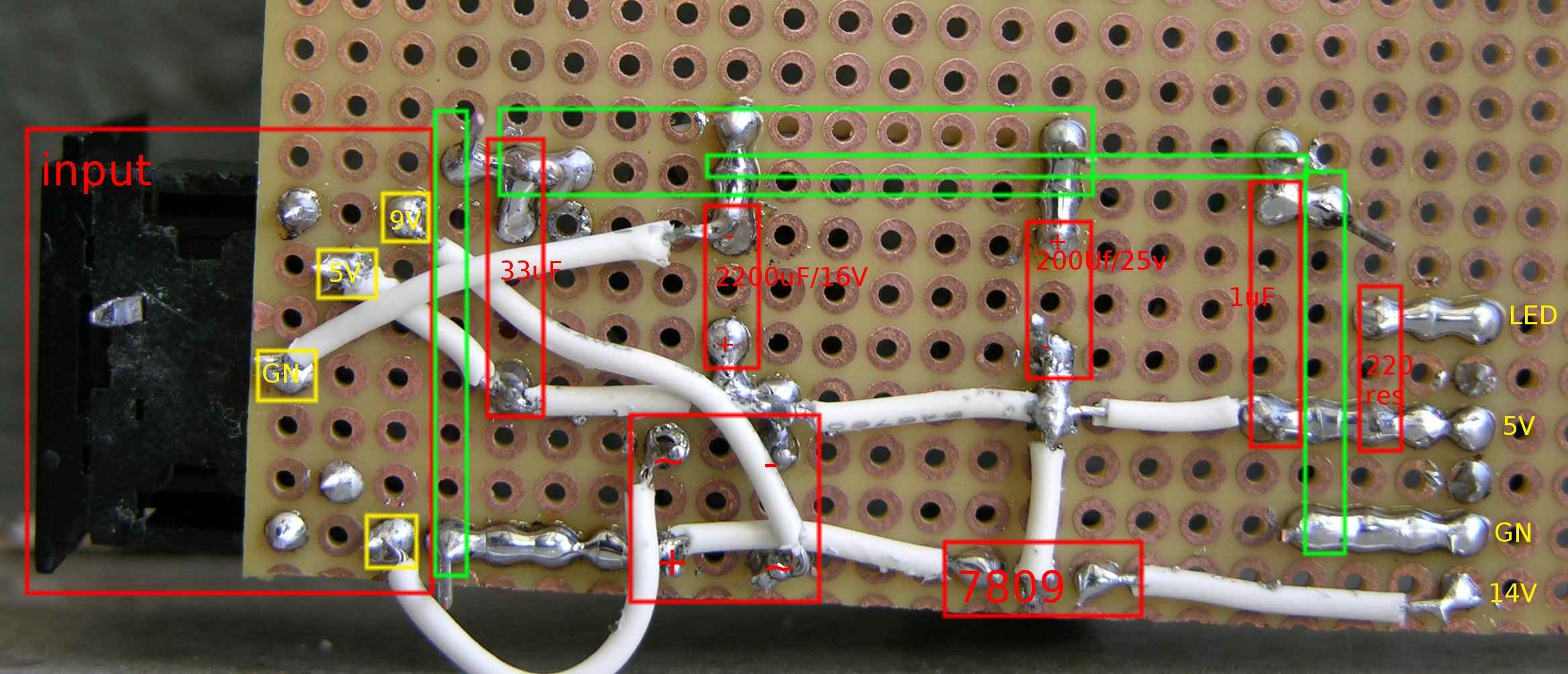
Not exactly. it think it was a problem with the female part of the input though. because right know i have soldered wires directly to the male part. But check out my board. And also tonebursts (the link is in a reply above). Compare my images to Altitudes PCB, and you can follow the lines around the board (i hope) http://www.midibox.org/forum/index.php?action=dlattach;topic=7626.0;attach=348;image Green marks: where i cut the cobber lines. Dont think they were all needed, but they helped me visualize. Red marks: Bridges. Blue/purple: components. hope you can read it. psu_top_korrekt.JPG -
mbsid no sound. all test passes
carsten_the_dane replied to carsten_the_dane's topic in Testing/Troubleshooting
Yep... maybe. thanks a lot for your help. I am very happy now, i have managed to create a tone. Yipii ;D Other problems have arrived, like no message on LCD and a bit of noise on track. But im not asking for help yet. Maybe i can figure it out myself. After all, i have seen text on my LCD earlier. Again thanks both And toneburst and altitude /Carsten -
mbsid no sound. all test passes
carsten_the_dane replied to carsten_the_dane's topic in Testing/Troubleshooting
Nevermind. I measured against ground. and it gives me 14.26V Nice. on to connect the everything. /carsten PS: i will post my circuit a little later. for others to see. -
mbsid no sound. all test passes
carsten_the_dane replied to carsten_the_dane's topic in Testing/Troubleshooting
i have recreated it on the a board like tonebursts. I can now measure 5V. Im a bit afraid to measure the 14V, how should i go about it? I think one of the problems with my old circuit (there were others) was the old input plug from the c64. i have now connected my circuit directly to the wires from the c64. And that seems to work. But again. How should i measure 14V? /carsten -
mbsid no sound. all test passes
carsten_the_dane replied to carsten_the_dane's topic in Testing/Troubleshooting
I get 1.7 on the input. Not right on the c64 plug, but on the first solderings in the circuit. hmmm, i hope you get it. Im sure this has nothing to do with a short at that particular point. I tried resoldering, but got the same result. In the 5V output, i get 0V. I have not measured the 9V yet. I think i will do another try today, putting the circuit on a board like toneburst: http://www.midibox.org/forum/index.php?topic=7626.15 It might create more oversight. /Carsten -
oh ok. so it would be pretty stupid to go with the cheaper ones without switch i figure. another question: these encoders from smashTV; are they detented but can be modded to be non-detented? do smashTV even ship to europe?
-
mbsid no sound. all test passes
carsten_the_dane replied to carsten_the_dane's topic in Testing/Troubleshooting
Ok. I have bought a new fuse (actually 3). Now 9V ac can be measured directly from the c64 PSU. The 7809 still gets very hot. I cannot measure 5V, and measuring right at the beginning of my vector board, where ground and 5V are, i get 1.7V. I have also noticed that after i turn of the PSU i can still measure low voltage (about .30) for a long time. Help please :'( Carsten -
Hi My local store doesnt sell rotary encoders. So i was thinking of buying them from SmashTV. But if anyone should know of a danish store that sells them, it would be easier. Should i buy them with or without switch. And what the h... does the switch do? Thanks /Carsten
-
Hi Im gonna get this thing... But first i have to finish the SID. I just want to ask. what creates the sound? Is it the SID and FM or something third? /carsten PS: now we are at it. I dont really want to create a paypal account. are there any alternatives.
-
;D Thanks
-
mbsid no sound. all test passes
carsten_the_dane replied to carsten_the_dane's topic in Testing/Troubleshooting
ok. so before i go to my climbing training, i have a short question: I have an amp with a 5A/250V fuse, can i use it, or does it have to be 1A? -
mbsid no sound. all test passes
carsten_the_dane replied to carsten_the_dane's topic in Testing/Troubleshooting
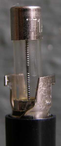
PS: is this fuse blown. The string is not cut, but it does have a strange thingy in the middle? -
mbsid no sound. all test passes
carsten_the_dane replied to carsten_the_dane's topic in Testing/Troubleshooting
Measuring 9V AC as you told me. On my multimeter i have V~ 200. i get 0.6 :'( Canibalized my mbhp_burner, i now have a 100nF capacitor on the psu. Also had a spare 7809. Tried to turn the psu on for 2-3 seconds, just to check if it would still get hot. It did. I will check 5V for short. But just want to hear your opinion. Now that all components are correct, what could cause the 7809 to become hot. Hot means almost untouchable. It must be a short right? /carsten -
mbsid no sound. all test passes
carsten_the_dane replied to carsten_the_dane's topic in Testing/Troubleshooting
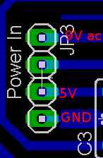
So it doesnt matter which one goes to which ~ on the rectifier? Damnit, i blame the dealer. Now i have to go to the shop once again >:( OK, i got the 5V and ground. no doubt about it. I wasnt shure what that last pin was for. i found a website saying one was 9V AC, the other 9V ac. i didnt understand the difference. Again, when i measure them against ground, i get nothing. Would you say the 1uF cap could cause the 7809 to get hot and block the 5V output? -
mbsid no sound. all test passes
carsten_the_dane replied to carsten_the_dane's topic in Testing/Troubleshooting
One more thing to make certain, Is this right: -
mbsid no sound. all test passes
carsten_the_dane replied to carsten_the_dane's topic in Testing/Troubleshooting
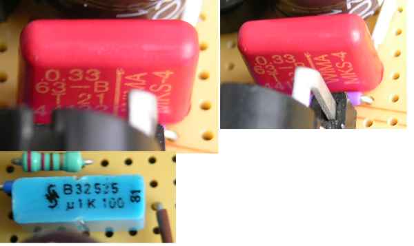
I think the caps are ok. One says 0.33 other says: u 1 K 100. Its a mistake in the picture. About the input connectors: This could be an important failure. I can measure 5V at the 5V pin, so i dont have any doubts about which ones are ground and 5V, and that pretty much gives away where the 9V AC is placed. But i cannot measure anything from the 9V pin, not with V== or V~. The 7809 gets incredibly hot - but i have read that that is normal. Question: When i measure at V~ on 200, 14V will look like 1,4 V right? cause that pretty much what im getting at the 14V output (which is weird, when i cannot measure the input) ??? Puzzled Still no output on the 5V out-pin /carsten -
mbsid no sound. all test passes
carsten_the_dane replied to carsten_the_dane's topic in Testing/Troubleshooting
Sorry about that. -
mbsid no sound. all test passes
carsten_the_dane replied to carsten_the_dane's topic in Testing/Troubleshooting
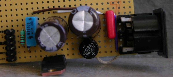
Ok. this thread is suddenly about a whole different problem than what it started out with. I have been trying to make the c64 optimized PSU, but i dont have any luck. Altitude provided me with a good quickview http://www.midibox.org/forum/index.php?action=dlattach;topic=7626.0;attach=348;image which i think i followed correctly. None the less i dont get the right meaurings. Infact i get nothing from the 5V output, and about 1V at the 14V output. Thats even worse than before, where i got 5V from both outputs. I am posting 3 pictures in the hope that someone will comment on them. (i have used GIMP, which is new to me, so i couldnt make it better than this) Thanks Carsten PS: i bought a new rectifier, just to make sure -
Optimised PSU Success, But Possibly Broken my Core Board :-(
carsten_the_dane replied to toneburst's topic in MIDIbox SID
Thanks I think i can make something out of the pics :D And thank you to altitude for the PCB, i couldnt find one as good as this. Carsten -
Optimised PSU Success, But Possibly Broken my Core Board :-(
carsten_the_dane replied to toneburst's topic in MIDIbox SID
Even though your psu is ugly (you said it, not me), do you think it would be possible for you to post a picture of the front and the back. Because im having terrible problems with my psu, and perhaps it would help me to decifer your pics. Thanks Carsten -
mbsid no sound. all test passes
carsten_the_dane replied to carsten_the_dane's topic in Testing/Troubleshooting
Forget about the 14 Volts. I think im tired, i should probably let it rest till tomorrow. Im not sure im troubleshooting very well. i think im confusing you with my answer. And i totally messing around with everything here. I will have a look at the PSU again tomorrow, and return to this topic. Thanks -
mbsid no sound. all test passes
carsten_the_dane replied to carsten_the_dane's topic in Testing/Troubleshooting
shit. sorry. the 7809 on the SID. As you have probably allready figured out. I am a total newbe to electronics. Hence, i have done all that was in my power to understand schematics and build the PSU accordingly to the PDF file. I think i have done it right. Question: if the rectifier of the PSU IS broken, wouldnt the rectifier of the SID module do the same. -
Can anyone explain this button
carsten_the_dane replied to carsten_the_dane's topic in Parts Questions
wauw, i wasnt aware of that feature. Thanks -
mbsid no sound. all test passes
carsten_the_dane replied to carsten_the_dane's topic in Testing/Troubleshooting
But i believe i have found the problem. Check out the bubble on the rectifier of the PSU. I have been very confused about the PSU, so you´re absolutely right. No hard feelings :) /Carsten rectifier.JPG -
mbsid no sound. all test passes
carsten_the_dane replied to carsten_the_dane's topic in Testing/Troubleshooting
When 15V are connected to J1, the first voltage test in the soldering guide of the SID module passes. Thats what i meant. The voltage drop from 5V to 2.8V is when im connecting the SID and CORE to my C64 PSU. I allready answered Mikes question, but here goes: The white foil-caps says: 1n J 100. Nothing else. To further explain. I had my doubts about these, but they were the only caps left (except what Mike had stuffed in for either 8085 or 6581).So i figured it had to be them. /Carsten detail.JPG