carsten_the_dane
-
Posts
176 -
Joined
-
Last visited
Never
Content Type
Profiles
Forums
Blogs
Gallery
Everything posted by carsten_the_dane
-
Pic-Burner: switching Clock fails
carsten_the_dane replied to modularkomplex's topic in Testing/Troubleshooting
The end of my topic (burner question) is about the same problem, only that it goes for all options in P18. Havent found an answer yet - it was just to let you know (not that you can use it :-\) Carsten -
Bought a new pair of batteries and readjusted the trimpot. Not plugged in to computer: J2: 12,5 MCLR#: 2.04 T1 b: 1.94 T1 C: 2.04 Plugged in: J2: 12,5 VPP ON: mclr#: 1.75 t1 c: 1.75 t1 b: 1.66 VPP OFF: mclr#: 2.04 t1c: 2.04 t1 b: 1.94 VDD ON/OFF: both 5 volts. Also, i have noticed that the red LED will turn on,a second or so after i turn it off, particularly for maybe the first minut it is plugged in. Could it be "plug n play" looking for something in the LPT1 port? [EDIT]: I answered this myself, and found a little app called "unplug n pray" which disables universal plug and play. And although the LED problem disappeared, i cant say if plugnplay was causing the problem. Anyway, it made no difference to the voltage... unfortunately. If i use linux (which i dont right now), would i be able to just feed the "channels" with a negative value? From what i´ve been reading, i can understand that bc337 works like an on/off dingsbums - do you think that it is broken. Based on what i descriped in the beginning of this thread, that i had turned around on the bc337 and lm317 which caused the lm337 to burn.
-
Ok. i will measure T1 tomorrow afternoon. My batteries are dead now, so i have to buy a new pair. Dont forget my new problem is that turn of VDD and VPP makes no difference to the voltage. see you tomorrow /carsten
-
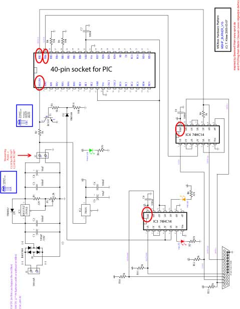
Should MCLR# really be 12,5 - As far as i can see resistor R2 drops the voltage to almost nothing just before mclr#. I have attached a schematics where i have marked the places i supposed to measure. Im pretty sure about this, but its just to be completely sure that its right. I have to affirm everything in order to troubleshoot.
-
I can turn the LEDs of, but it has no effect on my measurings. VDD stays on 5v and VPP goes from 1.5 to 1.88
-
I dont know what is wrong with the topic "burner question continued", personally i cannot view it. So here goes again. I have some problems with the formulation in the documentation. Could anyone please explain these sentences to me: "switch on Vpp - the red LED should go on. Measure the voltage at the MCLR# pin, it should be the same like adjusted before" - Should MCLR# read 12,5 - because mine only reads about 1,4. "Click on the "Data In" button - Data In should get the same value like selected with one of the above sData buttons." Anyway. All readings are good, except maybe that VPP reading at mclr# which seems kinda low. P18 says: division durch null, and does not reconize the pic. I dont have printers or scanners installed, and my cable is new. [EDIT]: Sorry i just saw that you put my question into the other thread. I dont mean to flood the forum with my problems. it just seemed appropriate to make a new thread, since my problems had changed a lot since my original thread.
-
About the red LED. Should it be 12,5 - or the same as before plugging the burner into the computer? The documentation is a bit vague.
-
NOOO (or maybe yes) - one week of troubleshooting all because i didnt know what a trimpot was :-X Well, that will teach me to read about all components and read through all documents before starting the "real" midibox project. Its working now, and i feel sorry that i have wasted your time like that. Carsten
-
Sorry my mistake again ;D Though the connections are made right i have been measuring at the wrong places. I had changed O and A around in my head. So the measures should be like this: J1: ~ 18 volts 317: I = ~ 18 volts 317: O = 2.1 volts J2: 1.41 volts Dont know if it changes anything
-
Could you please take a look at the datasheet found on this page http://www.datasheet4u.net/html/T/L/3/TL317_TexasInstruments.pdf.html As far as i can see, the I,O,A placement on the TL317 is different from the schematics found on ucapps.de. - Or what ???
-
I think when i had bad results i had tried changing the polarity, just to check if that might be the fault. Could this cause other compoonents to malfunction? - But generally i have been using the pin closest to the lpt as negative and the other as positive. I will put the recitifier back in place, so theres no doubt. Anyway, i was thinking of just bying all components again (except the sockets), and start over. Could it be a shortcircuit on the other side of the board. - I have checked but havent found any that i could see. Just to make sure: theres no polarity on resistors and ceramic capacitors, right? Well. Thanks again for taking some time to help me Carsten
-
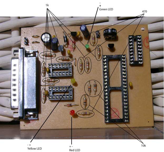
Here is a picture of my board, with some additional comments. You can see how i have placed to LEDs, and if there are any problems with my setup otherwise. The little blister on the voltage regulator is because this image is from before i moved the lm317, as explained earlier in this thread. I hope you dont get to confused by my drawings :-\

-
My bad about the 0 volts at j1. New 317, New measures: J1: ~ 18 volts 317: I = ~ 18 volts 317: O = 0.14 volts J2: 1.41 volts This time i couldnt possibly have done anything to break the 317. No green lights either. So whats your advice? (EDIT): Been spending some time going over the schematics. And i havent been able to find any errors in my setup. Did i say that i have removed the b80c800 rectifier, and just uses a bridge. but than shouldnt mean anything, right?
-
I appreciate it, but there is no need for that. I dont live so far from an eletronik store. Even if it is fried, shouldnt i be able to get a reading before the LM317?
-
thats to bad. cuz now im getting no read at all. I connect the (-) from the battery to the pin closest to the LPT connector.
-
:-X whoops. Ok, the setup works, i get green light and a measure on j1 and j2 at 14.5 But it puzzles me that i should connect the batteries at J1 and J2, at the pictures of you making the burner, the power clearly comes from J1 only?
-
Hi First of all, thanks for moving the post, i didnt want to cross-post. And also thanks you for taking the time helping me. Here are the measures: J1 = 8.92 LM317:I = 8.91 LM317:O = 0.13 J2 = 1.38
-
Using the multimeter i was measuring volts, particularly looking at the TL317 (LM317 in the schematics, read above). when i make connection between what i would call finger 1 and 2 on the TL317, the green light lights up quite clear. What could this mean? (finger 1 and 2 being first to the right and second to the right, looking on the flat side of the TL317)
-
Electronics is completely new to me. So if you could please help me on this. Today i changed the 100uF 16V rectifier with a new one. Its a bit different; it says 100uF and 100V, i hope this is not a problem. I also changed the first voltage regulator LM317 - this one is changed to one called TL317. The man in the shop said it was the same. Is this a problem? I think i have manage to find the problem is with the LM317 (now TL317), where the voltage drops from about 9 (not quite 12.5) to 1,5. Any suggestions would much appreciated? Thanks Carsten
-
Lol. im getting a reading that says between 0.02 and 0.05 volts.
-
:-X i think i fried the LM317 voltage regulator. I had accidently switch around the capacitor and the "voltage testing pins". Whoops It almost caught fire :-\ How on earth can i troubleshoot my board now. Maybe it was just the regulator that died on me, but perhaps all the parts got fried ??? Nice to know what you´re doing carsten
-
well i skipped that step and bought 2 nine volt batteries. But there is no light in the leds. Could i possibly post pictures of my board here, so that someone could check it out for errors. Because i dont know what to do now. Carsten
-
Changed the subject of this topic a bit, since my original problem didnt have much to do with my problems now. Please read on...
-
shopping, thinking about spare parts
carsten_the_dane replied to carsten_the_dane's topic in MIDIbox SID
No no, thats fine :) -
shopping, thinking about spare parts
carsten_the_dane replied to carsten_the_dane's topic in MIDIbox SID
thanks for all the feedback. Appreciate it :) /carsten