Ixox
-
Posts
80 -
Joined
-
Last visited
-
Days Won
3
Content Type
Profiles
Forums
Blogs
Gallery
Everything posted by Ixox
-
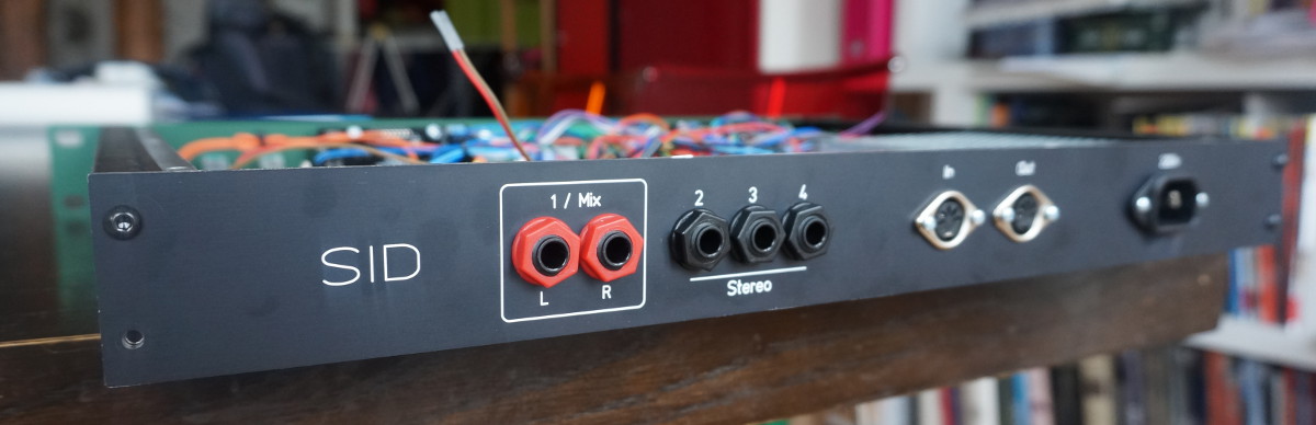
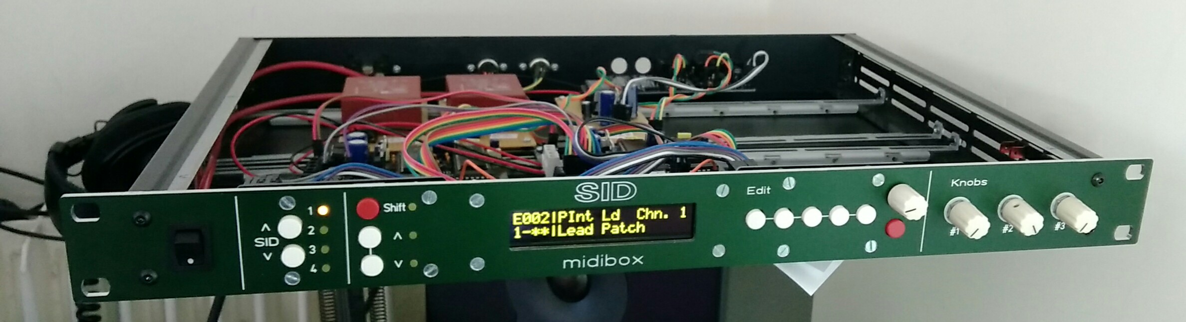
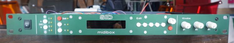
Everything is working fine, so here are my files. https://github.com/Ixox/midibox-SID I didn't have time to play a lot with this great machine, but i'm very very happy with the result : Looks great Sounds fantastic The 3 analogs Knobs are very usefull (awesome on Filter Freq and Detune) The oled screen is readable under any angle Powered through a single power cable (Transformer is in the rack). Active mixer (-12/+12 v) for all 4 full volume voices mixed together... or independant output when plugged. 1U rack allow it to be always usable ever if my desk is a big mess ! Thanks a lot Thorsten for all you work that allowed me to spend a great time building this Xavier
-
Everything is now powered with the meanwell rt-65b power supply and the signal/noise ratio is very good. All 4 boards are in place, though i only have 3 pairs of 8580. I still have a few things to check/fix/finish then i'll post all my files in case someone is interested.


-
Yep... The rack is the 1U here : http://www.frontpanels.de/nrg-case-19-enclosures/ They also made the panels. Frank does a great job with this site ! The mounting rails are usefull to put the PCB in place without drilling the case. Xavier
-
Thanks :) I use SID 8580 only. With only 1 board, the ratio signal/noise is very good. I have 2 transformers 6Vac and 9Vac, that goes to the boards in parallel. Each board has 2 diode bridges, one 7805 and one 7809. The result is a high background noise as soon as i plug a second board. The meanwell rt-65b is a switching power supply which has a very good reputation among eurorack users. It provides a triple output : 5v, 12v and -12v and one ground. I need the -12v for my mixing PCB. And it's 38mm high which is perfect for the 1U racks. I should have it early next week. Xavier
-
Work in progress. The background noise is terrible with the current solution when i power more than 1 voice card. I assume it's because of the multiple ground reference. I'm waiting for a RT-65b power supply and hope it will fix the problem.

-
OK I got it :) I was touching " TRISB[3:0]" during the wait_unbusy loop. I now have a OLED compatible display driver that do not kill CAN communication :)
-
I have some news. I got the communication working if i remove the custom LCD code (MIOS_LCD_TypeSet set to 0x7) and put back my LCD display. With my custom OLED driver, the CAN is broken. Thorsten, if you read this, where is Init_Port ? It's written in the LCD driver : "Initialization of Ports: done in Init_Port" As the CAN pin is mapped on the old pin3 of the LCD driver, i think that can be the cause of the problem. Custom LCD de-init ECAN ? Do you have any idea ? Thanks
-
Hi Jeppe, I have this same problem, maybe you found what was wrong ? Is it supposed to work with any number of slaves ? I only have one master and one slave for the moment. Pic IDs are 0 and 1. MIOS and firmware are flashed on both. Diode is in place on each board, RB3 pin is pulled up on the master. Master and Slave are connected through this pin. When i select other than SID1 i get "SID(x) not available (CAN disabled)"". Any idea of what can be wrong ? Or anything else i can check ? EDITED : Firmware on PIC ID=1 is OK. If i plug the display to the PIC1 board it boots and display "CS disabled". Xavier
-
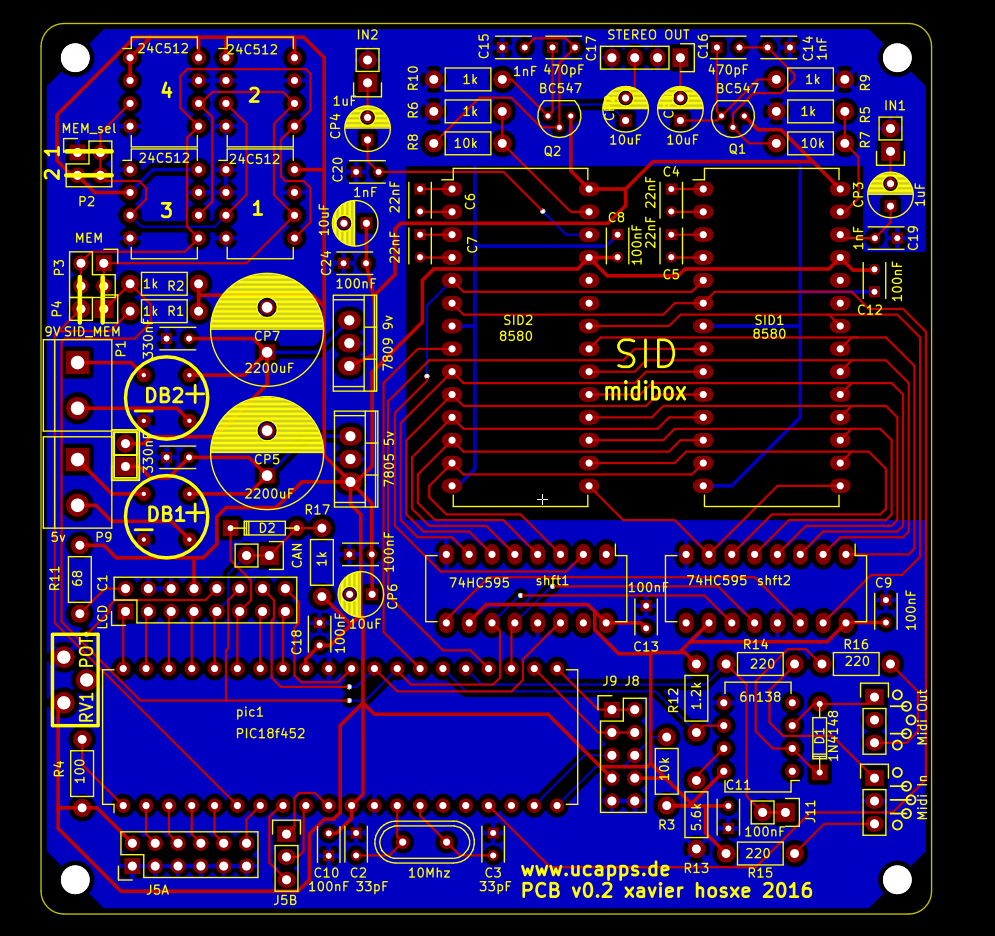
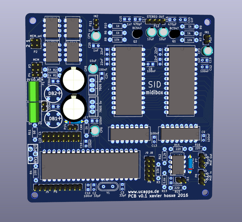
PCBs arrived... I soldered the Mainboard and it works fine (sound, midi, mem, display, DIN). But i found a few mistakes, i'll fix them in SIDMB v0.4. If you have small PCBs (<10cmx10cm) to make, look at elecrow.com, prices are amazing and service is great. I just ordered the front and rear panel. Next step, solder the other PCBs and put everything in the rack. Xavier

-
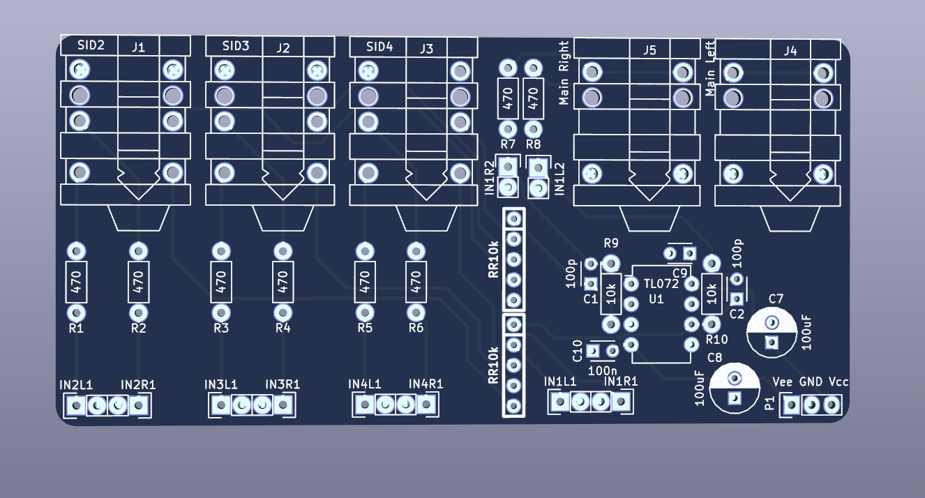
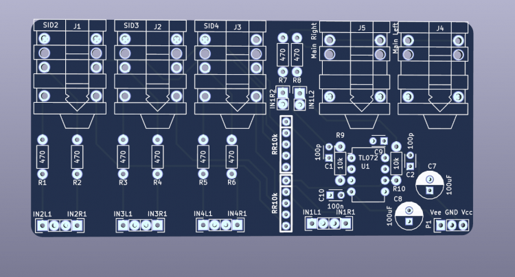
I've ordered the PCBs with this aditional one : This will mix all SID's voices to the main right and left jacks. Pluging individual SID2, 3 or 4 jack will remove them from the mix. Copied from Ambika mixer This one requires a dedicated -9/+9 DC but it can be done with a very small transformer. Xavier
-
Yes thanks for you old post. Very usefull :) I'm not sure the MIOS clcd driver initializes perfectly the 4 bits mod. http://svnmios.midibox.org/filedetails.php?repname=svn.mios&path=%2Ftrunk%2Fmios%2Fmios_clcd.inc Look at page 46 of the HD44780 spec : https://www.sparkfun.com/datasheets/LCD/HD44780.pdf The app_lcd.inc i attached follows it more strictly. Also i think the clear() commands should have a wait of 2ms. It's not very clear in the spec as the 1.52ms is mentioned for the "return home" function, but that was a bloker for my OLED to work, and it's what LiquidCrystal (HD44700 famous library) does. Best, Xavier
-
Hi, I worked a little to get my OLED display working with the SID firmware. It didn't work with the out of the box MIOS driver, my oled remained totally black. Here is the OLED i have. It's now working wotj the following modifications. What must be done is to enable Custom LCD in main.inc USER_Init function. ;; CUSTOM LCD movlw 0x07 call MIOS_LCD_TypeSet Then replace app_lcd.inc by the one attached here in "midibox_sid_v2_044/src". It's based on the file found here with some init sequence and timing modifications. Best, Xavier app_lcd.inc app_lcd.inc
-
OK will be easy to move the right group of track to the left. There's space. thanks :) Trace widths is 8mil. It's Kicad default. That's what i used for the preenfm2 PCB it works well. I may make them wider for the analog part though. Power trace width are 16. Yes the four banksticks can be 1234 or 5678 depending of mem_sel switch in the top left which sets 24LC512 A2 pin to GND or 5V. They are not by default connected to pic. Need 2 jumpers P4=>P3. Top left. Master PCB/PIC : P4=>P3 shorted. Bankstick set to 1234. And the 2 left pins of P3 connected to the first salve PCB P3. Slave PCB/PIC #1 : P4=>P3 free. Bankstick set to 5678. And P3 connected to the master P3. Banksticks on this PCB are so seen by the master PIC only. Like this the Master PIC see 8 banksticks.
-
New version with some modifs : . SID area ground . More conveniant J5 . moved LCD contrast pot . Add little space around the regulator

-
OK i found that for the SID grounding : http://www.midibox.org/dokuwiki/lib/exe/fetch.php?media=mb-6582:mb-6582_base_pcb.pdf Interesting :)
-
Hey, thanks a lot for the feedback. . Good idea to modify J5, specially to ground the useless analog entry. I'll do that. . LCD and CAN : I use simple female to female wire so there's no need to much space around the connector. Should work like this. . Trimmer pot too close to the board edge ? Yes right :) . I removed the brightness pot. Too many components, in adition the original one does not work on the LCD i have. On this PCB : simple GND/VCC + resistor for the LCD LED. . voltage regulators would be better elsewhere. Yes. Not sure i'll modify that, too time consuming ;) . Two bridge rectifiers because the idea is to feed it with 2 transformers: one 6V and one 9V. There's a jumper though to short both power input after the bridge rectifier for eventually feed the 7805 and 7809 with a unique 9V only source. . It would be great to have a ground zone around the SIDs. Does it include all SID GND pins ? Do you have any detail about that ? (EDITED : just realized there is only one GND pin on the SID !) 10x10 cm was a major constraint to get cheap PCBs from elecrow.com ;) Thanks again :) Xavier
-
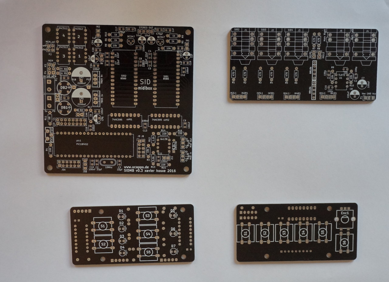
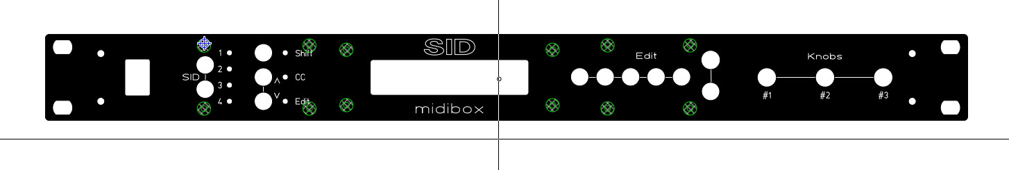
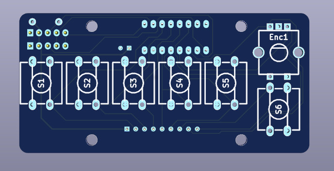
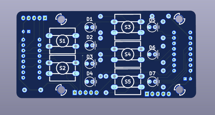
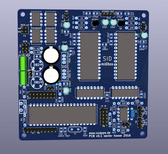
Hi, As i said in an other message, my original plan was simply to put my old SID V1 back to life. I wanted to put it in a RACK 1U because i have too many little boxes everywhere around here. Very quickly i decided to upgrade the PIC and add a second SID to have a stereo V2. Then the project has grown. Here is the current status... The rack front panel (screenshot from front panel designer) : The knobs will be pots. I played a little with one pot on my mockup and it's very fun to control parameters with them. The 2 surface control PCBs : (They include the 74hc595 and 165 so they can directly be plugged on J8/J9 on core) And the most ambitious one : This is a Core + 2 SID on 10x10cm PCB + CAN (diode & resistor) + 4 mem chips. (With one jumper and 2 wires it's possible to use the 4 other 24LC512 of another PCB in adition to the main local 4.) One of the goal is to easily link up to 4 PCBs like this as SID v2 allows. I'll double check the PCBs and will order them. So there will be some time before the next update. I'll make all the files of this project available when it's finished. PCB are made with Kicad. Thanks Thorsten for documenting so well everthing, Xavier

-
Thanks Peter for your reply. My keyboard for any reason was sending CC#8 with aftertouch which is interpreted as Filter Channel value by the firmware. As the last value is always 0, it actually disabled the filter for all voice. I modify the aftertouch CC of my keyboard and it's now working perfectly ! Xavier
-
Update : I inserted a midi monitor between my keyboard and the SID. Seems like the firmware does not like at all the Aftertouch midi information that my keyboard send 0.5s after the begning of the note if we hold the pressure. This aftertouch midi data kills the filter. I tried with a keyboard without aftertouch and it's working fine. Anything to do to fix that ?
-
Hi Thorsten and all, I'm upgrading my old SID V1 to a stereo V2. I upgraded the PIC, remove the useless LCD data connection, and added the 1k pull-up to the CAN receive input. Almost everything works, sound, stereo etc... But I have a problem with the filter that only works when i play short notes. If a note lasts more than around 0.5s, the filter is disabled and stop working for all new notes. It works again if i modify it's style (Low/Band/High) or if i load a new preset. Then again, it's being disabled when i play a "long" note. This exact behaviour is the same for both the SID modules i have. And the filters are disabled at the same time on each SID module in stereo mode. The filters of my 2 SID modules work perfectly with SID V1 if i put back my old PIC 18F452. Any idea ? Best, Xavier EDIT : aditional info : Core R4C and SID : R3. MIOS 1.9h, Firmware 2.0.44.
-
Hi Thorsten, Thanks for the reply. Yes i've found a populated core and SID V1 boards that were useless in a box for a long time. I'll try to put the synth in a 19" 1U Rack with the simple CS. But after i posted my message, i've ordered an other SID PCB, a 8580 and a PIC18F4685 to turn my old midibox V1 into a stereo V2 :) Best, Xavier
-
Hi, I'm trying to come up with a PCB for the minimal surface Core8 based SID V1. I have a hand-wired proto with one 24LC512. I modified the setup_8580.asm file with "#define DEFAULT_BS_TYPE 1" and recompiled the firmware. It works fine, the 24LC512 can save 2 banks (A & B). On the PCB i have some free space and i wanted to add a second DIP8 for a second 24LC512. I'd like the second 24LC512 to store bank C & D. My question is : must it be wired as the A=1 or A=2 24LC256 based one this shema: http://www.ucapps.de/mbhp/mbhp_multi_bankstick.pdf Thanks, Xavier
-
I'm a bit late on this one... But thanks Thorsten, i'm glad if you find something useful inside. For those who can be interested, lots of new things since 2 months. - It now has 2 step sequencers usable as source in the modulation matrix. - External Midi clock synchronization for the 3 LFOs and 2 step sequencers - Kind of gate on the main output That allows to get sound like this by just pressing a few key on your keyboard : http://xhosxe.free.fr/PreenFM/PreenFM_MidiClock.mp3 (Drums are VST Drumaxx). No assembly in the new feature ;-) Xavier
-
I have Genome on my ipad, and used it a bit. It's very interesting on the paper, it allows to synchronize other synths on the same ipad such as Sunrizer, or the drum ModDrum and and at the same time send midi out to an external expender. It has tons of good ideas. I use version 1.06 and unfortunately it's too buggy... bad selection, uncorrect copy/paste, crash, problem with the built in keyboard, weird behaviour in song mode. Also the fact that with 2 fingers you can scroll OR select depending of the space between the finger makes it not easy to use. I contacted the author who told me a new version will arrive soon. If you bought it since your post, let me know what you think. Xavier
-
Too bad, i'd love to see this link ;-) Xavier