lylehaze
-
Posts
613 -
Joined
-
Last visited
Content Type
Profiles
Forums
Blogs
Gallery
Everything posted by lylehaze
-
Some more thought.. Using "old school" 74XX buffers would have a much greater fan-out into CMOS inputs, though I'd have to check the "defined levels" for compatibility. I usually avoid the need by sticking to a single logic family. If we run a lot more than eight, we might be better off running in groups of eight at a time, just for access time. The entire "line" has to be re-loaded for every change. I'm sure that eight boards is not a problem, but 16 will take twice as long. I wonder at what point it will become noticeable? I have burned out on Eagle, so I switched over to MPLab today. I'm doing a re-write of the software to support using a single channel board for each mono input. I'm trying to add cool stuff, but I readily admit that I'm writing to serve needs that are far beyond my own. At some point in the next few days I hope to diagram what I'm putting together, and again request feedback and suggestions. I don't even know the right terminology to describe the signal path. Mono input has gain and level, then panned into the main stereo pair. Also support for two separate mono effects busses, each may be selected as pre or post-fader, each has it's own associated FX send level. Mute control. How far does mute go? Just the main, Just the FX, one for each? I'll plot out the CC numbers for each control tonight. Code more tomorrow. If you can contribute to the above description, please do! LyleHaze Edit: CC7 = Channel Volume. For the "main stereo mix" and "Post Fader FX" CC8 / 10 = Pan/balance (combined) for the main stereo mix CC11 Expression. A "secondary" volume control, sometimes used for fading without altering the mix levels. CC12 FX1 level CC13 FX2 Level CC80 to 83: "General Purpose" buttons, possibly we could use to select FX1 Pre/Post, FX2 Pre/Post, FX1Mute,FX2Mute CC96 "Increment".. Channel Volume? CC97 "Decrement".. Channel Volume? CC120 "All Sound Off".. By mutes, or full preset? After an "All Sound Off", how do we get it back "On"?? CC121 "Reset All Controllers". Sounds like we could load a "preset all to default state". User defines that state! I'm gonna have fun with this one! I still need to research "SysEx Master Volume". I saw it somewhere around here. Lyle LyleHaze
-

DIY audio patchbay with digital routing....How hard?
lylehaze replied to Nomical's topic in Design Concepts
Forum chat doesn't work on my primary machine. If we do happen to go E-Mail, I'd love to be the official "lurker" on this topic. LyleHaze -
Stryd, The limit is not an audio one, it's about two of the three digital signals that control the mixer. (CS and SCLK, I think) The all the digital signals EXCEPT for SDI/SDO are daisy-chained together, so by the time you have eight boards attached, you have a single MidiBox digital out feeding eight inputs. I have not looked deeper, but most TTL signals offer a max "fan-out" of ten. I'm guessing eight is a safe limit. But I could be wrong, I have not tested it yet. Better to stop too soon than to build a less reliable device. Workarounds include: 1>Using buffers to "pump up" the digital signals before we use them. 2> Buffering them at every channel board (more chips, bigger board BOOoo!) 3> Using a separate pins for every group of eight. (easy to do) 4> Just keep adding on until it fails, then remove the last two channel boards for margin! (Unfortunately, this is likely to be the most popular) As always, I'm open for suggestions, discussion or friendly debate. LyleHaze
-
I'm glad it is well received. I was a bit busier today, so no eagle work, but I did put together the text part of "input options". I'm just going to describe 3 contrasting choices, and let each user refine the details from there. I can see that I'll need to clean up the source code as well, or at least write a version that handles mono inputs into L,R,FX1,FX2. One flaw in the boards: No mounting holes. And no room to put them, either! Oh well, I'll save "perfect" for my next design. I can use the 7805 tabs to mount the master end, anyway. Thanks to everyone for the support and encouragement. It helps a lot! LyleHaze
-
You are correct. Sorry if I described it poorly. There are only 4 volume controls in each PGA chip. Lot's of options, but none of them involve stacking PGA chips onto a single board :-) With the "4 in to 4 out" option there is no mixing involved. Just simple audio level control of four separate channels. That might be useful for some projects, but it's not a mixer at that point. I hope I didn't mislead.. I am a bit excited about this project. LyleHaze
-
@DrBunsen Yes, 4 separate inputs can be buffered, volume controlled, and each brought out on a separate wire, OR each mixed to any of bus A,B,C, or D. If you leave out the SIP resistors in the last step, then the 4 signals will just sit there and wait. Probably a more likely use is to use the entire channel board for one mono input. Just build up a pair of input caps, a single op-amp, then drop the signal into all four channels of the PGA. Then we re-name the four mix busses as Left, Right, FX1, and FX2. If you want a "private" FX loop for each input, then wire directly to that board instead of bussing them together. As was discussed previously, each FX send may be pre or post fader, that's just a software change. Finally, the size. I think the max number of channel boards we can safely gang together is probably 8, due to signal fan-out. But those would assemble into a 4" by 4" square that is only an inch tall. It would still fit in a 1U rack case. re:Docs. It's the first time I've tried html format. Glad it worked. I like formats that can be read on any OS. LyleHaze
-
DIY audio patchbay with digital routing....How hard?
lylehaze replied to Nomical's topic in Design Concepts
OK, I have (possibly) finished the channel board, and even scraped up the beginnings of documentation. Since some here might be interested in how I will try to manage my input buffers, I have posted the current documentation in a zip file, formatted as HTML for the widest audience. Since it's for another project, I posted it there. If you'd like to see it, check the latest post in the MBMixer thread over in user-projects. If someone knows how to add a link here to that thread, or better yet, a link to the .zip file, please do! Respect, LyleHaze -
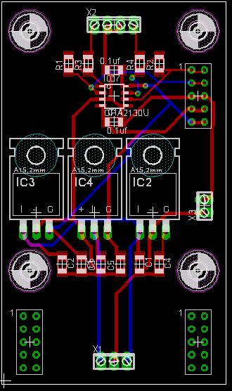
After some discussion in another thread, I want to release some info on the redesign. Only the channel board has been done yet, but the changes have been pretty big. I'm about 90% sure that I'm done with the channel board. Now I need to make a matching master board, and I'll be ready to get started again. The attached files will describe the options of the board. What it doesn't say much about is the size. This board is now <4 inches by <1 inch. If you get your boards from Sparkfun, it should bill out as 4 square inches. If you get them from Olimex, you should be able to fit 6 of them on a single board. In the interest of making a document that will read on any computer, I zipped it up as an HTML file. I hope it carries the images properly to everyone. As always, I'm open for suggestions, LyleHaze chanbrd.zip chanbrd.zip
-
DIY audio patchbay with digital routing....How hard?
lylehaze replied to Nomical's topic in Design Concepts
I have been busy trying to make the MBMix board as small as possible, because I'm a cheap bastard. The good news is it is now 4 square inches, but it doesn't offer much for connectors, as they were almost half the board space in the previous design. I'm using "board stacking" pins for all buss connections, power and audio. (that's cheating, I know) But what I have that might be useful for this project is the input buffers. I've managed to come up with a "configure at build time" plan that supports balanced, unbalanced, various preamp gain settings. It will even allow addition (off board) of a switch for phantom power, as I'm guessing some people will need that. If you don't mind taking up a bit more space, These input buffers can have the settings changed later by "plugging in" a new configuration connector (usually just a few resistors on a 6 pin header). This part of the board is hopefully going to be finalized today. But I can't offer a tested and "proven" design until the boards get back from the fab house. (I use a REALLY SLOW board fabricator, because I'm a cheap bastard, remember?) Anyway. That's all about my project. I don't want to intrude on this topic, except to offer my own designs if you want to see them. I'll bring a few jpegs home tonight just in case. Make Beautiful Music, Lyle -
DIY audio patchbay with digital routing....How hard?
lylehaze replied to Nomical's topic in Design Concepts
OK, I'm checking in briefly. First, a few disclaimers: I'm already up to my neck in another project. I am NOT an expert in anything, just a resourceful amateur. :-) I think this project has a good collection of people much smarter than me already. That said, ANYONE (or even EVERYONE) should feel free to tell me how wrong I am, or even where to shove my opinion. No problems. Nomical, You asked a few questions I'd like to comment on: 1>LED Matrix and/or display: For my own project, I chose to separate the "real audio handling" from the display and controls, as a great advantage comes from separating them. i.e. Take the controls and display to the mix booth, leave the audio matrix backstage. Saves a LOT of audio cable. 2> Multiple In to one Out. Can be done, but you have no control over the relative levels without some sort of mixer (coming soon!). 3>One in to Multiple out: Certainly do-able, but you'd better have an input buffer to assure a low signal impedance. 4>Controls, local or remote: Minimal local controls OK, but the primary should be remote, see #1 above. 5> Remote connection method: RS232 or USB?? Bah! MIDI is multiplatform, and I know a GREAT little controller called MIDIBox. MIDI can also be sequenced for dynamic changes. 6> Balanced/Unbalanced: Switches are available both ways, but dead-mixing balanced signals is beyond my comfort zone. Someone in an earlier post suggested transformers to adapt balanced to unbalanced. If we have +- voltages, Op-Amps do much better (and cheaper) than transformers. 6+7> SPDIF/other digital formats: All signals will need to be converted to a common type for switching. Presumably analog, and preferably unbalanced while on-board. ANY type of input and output buffers can be built, but I think the board in it's current direction is going to be an analog switch. Remember, I'm not driving, just offering my unsolicited opinion. Feel free to tell me to get lost. I'll be watching from the back row, at least until I finish my own project, which might combine nicely with this one. It looks like fun! Lyle P.S.: Respect for all those involved. -
DIY audio patchbay with digital routing....How hard?
lylehaze replied to Nomical's topic in Design Concepts
Damn! I look away for a minute and you guys take off running. It looks like great fun, but already well beyond what I need. No harm in that though, I'll continue to cheer you on from the sidelines. I did notice one thing from a previous post: The Midibox Mixer is really using NE5532 op amps. I find them to be very clean and quiet. As mentioned before, most op amps are pin compatible, so it's up to the individual builder. I might have even used a different part for the eagle files, but the pinout is the same. Unless you want some REAL preamps. Then you'll need to change the pinouts over for some 12AX7s. Oh, and some power supply changes too. :-) Yeah, it's meant as a joke, but I have already been asked if I can adapt the MBMixer to replace the front end of a Fender Amp Head. You never know what the next guy will try to do with it. :-) LyleHaze -
After a full day of considering options, I'm going to delay sending the proto order out for a few more weeks. I'm changing the circuit to make it a> More Affordable (slightly) b> Higher Fidelity c> Easier to reconfigure to different applications, based on the comments I have received so far. And also hopefully more compact. (GAAA!) Besides, I just had to replace the power supply in my AmigaOne, so I'll need a few more weeks to get my hobby cash together. But I'm still open for more suggestions.. LyleHaze
-
Interesting.. to me at least. It may be old hat to others here. Now, to change from the "functional" diagram to an actual signal path.. Consider this: For the moment, ignore the FX loop. Let's focus on the main outputs. You have taken a mono signal, through a input buffer for good impedance, then through a single volume control and then a panpot. In reality (for some cases of reality, anyway) we would eliminate the level control, and only have two "volume pads" one feeding main to Left, and one feeding main to right, The current code does exactly that. It converts a volume setting(both channels), then applies a balance/pan setting, resulting in volume left and volume right. Your controls are separate, but the end result requires only two PGA channels. Now we add an FX loop. Whether it is pre or post fader is complely under software control. It makes no difference to the hardware. You are now sending the incoming (mono) signal to three possible destinations. Left, Right, and FX. Each level may be software controlled. Since these things always come in even numbers, it would be easy to mix a mono signal into a strereo buss plus two effects sends. that would require one channel board for each channel. Or you could re-wire the thing for one fx send and the other for an FX return level, but no control of FX return pan. Maybe better to bring that back into a separate channel board. You've made this much clearer for me, is there anything I can help to explain for you? Everything I described above can be done, mostly with software changes. Minor issues: The current software uses CC7 and CC10, I think, for volume and pan/balance. Are there "standard" controls for FX send, or do we hack something nonstandard up? I am lucky to have LOTS of extra MIDI ports available, but I realize that most people don't. (LOVE my UM-880) LyleHaze [edit] it looks like CC91 and CC92 would be fair choices for FX1 and FX2. I wonder how many people want to mix stereo pairs, and how many want to mix mono sources into a stereo mix?
-
4 Mono inputs? Yes. Minor changes in hardware and software. Hardware change for four SEPARATE outputs: Leave 4 of the SMT resistors out when assembling the board. "pick" the 4 separate outputs off of the right side of CN5. For four inputs mixed into a single channel, just short the left and right mix terminals together. (it's OK, really!) Software: The current mixer software keeps separate tables for sixteen volumes and sixteen pan/balance settings. It re-calculates all of these into 32 volume settings which are sent out to the PGAs. So you just take that "re-calculate" call out, and load your values directly into the 32 output registers. There are LOG conversions available to keep the levels right. Effect Loops. Hmm, I've never done those. If you want two stereo busses (main and FX) then just separate the outputs as above and use two summing amps. (one on the master, you make the other). Or make two master boards and call the second one "FX". (on a different MIDI OUT if you go above 8 pairs). You CAN tie the inputs together (VERY high impedance, esp if you leave 4 resistors off each of the second set of channel boards) If you want an individual FX loop for each channel (or pair) then you might have to cut four traces. But this is guesswork off the top of my head. It would help if I could see a function diagram of where the controls are in the picture. If you need a better answer, I'll need to see exactly how you want it to be arranged, like whether you have separate volume controls for the main and FX send (and FX return) and if we are stereo or mono. LyleHaze [edit] Duh, I missed the obvious one. Mono input panned into the stereo mix. Yes, easily done, very minor HW changes, no software changes needed. BUT.. Only two inputs per channel board instead of four, and no MIC preamps on board, though there is a provision for adding them.
-
re Bulk Order: Not likely. Just ordering one set of boards will cost more than I can easily afford. (Prototype costs are a bit much). I will probably make the gerber files, eagle files and documentation available. I want these to be available to everyone, but I can't afford to manage the project. If giving them to one person makes that possible, then I'll do it. If giving the files to everybody is a better way, then I'll go that way. I don't want any profit from this, but I can't afford to invest much into it either. I'll spend $85+ for a set (one master, four channel boards, eight pairs stereo mix) That will "prove" the board files, then I'll figure out what comes next. At least, that's the plan now. I hope to finish the master board design tomorrow, then spend the weekend checking my work. The hand wired ones have been working great, but I never went past four pairs. I'm looking forward to the upgrade! LyleHaze
-
re:heatsinks I don't think it will need them, but I have not built up a full 16 pair set yet, and it will also depend on how high the unregulated V+ is. I usually hang the + regulators off the side, so they can be mounted with their backs to the case. The - regulator tab is not at ground, so it will be either no heatsink or a small, ungrounded one. I like the idea of the mixer carrying it's own regulators, to keep it simple. I thought of adding a bridge and caps, but there is NO ROOM on such a small board for big capacitors. As it is now you have the transformer, bridge, and caps off board, then attach the V-,GND, and V+ to the master board. I may work more on that today. It's off to work I go! LyleHaze Follow Up: Based on the datasheets, the + and - 5 volt analog regulators will be supplying about 270ma for a full 16 channel mixer. The +5 digital will be supplying almost nothing. I have moved all 3 to the left edge of the master board. 2 can be case mounted, 1 MAY need a heatsink.
-
These boards link into a chain. I think we have three options for linking them. We can put male headers in all positions, then use 2 IDC connectors on two inches of 10 conductor ribbon cable. Simple, easy to do, Smash has all the parts available. Boards arrange from Left to Right. Or we do the same thing with about five inches of cable between the connectors. Now we can "stack" the modules into a cube. All the mounting holes match. Simple, modular, if a bit "Borg" in style. Finally, there has to be an offbeat option. On the right side of each board we mount a female header, facing up. On the left side connectors we solder a male header, coming from the BOTTOM of the board. Now the boards really "piggy-back" together, with no cables between them at all. The connectors align with the mounting holes for just that reason. We can add spacers and permanently piggy back the boards together. So, there's three options for joining boards together. Time for bed. I'll check for comments in the morning, LyleHaze
-
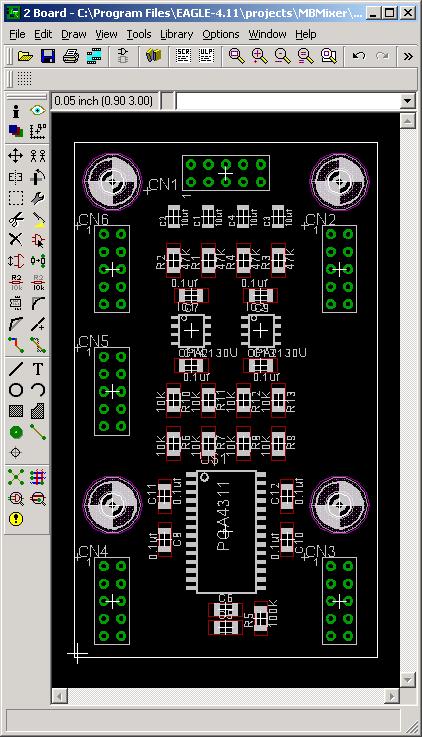
OK, the channel board is just about finished. The master board is about 70% 4311 board description The target application of this board is to mix two incoming stereo pairs onto the stereo buss of the mixer. (Volume and balance only). By leaving off certain parts and adding an extra connector, you can change that to other applications if you want. The board contains a PGA4311 chip. There are also two dual amplifiers, used to buffer the incoming signals. All three chips are SMT, along with all resistors and capacitors. There are six ten pin connectors around the board. Five are normally used, CN5 is only needed if you re-configure the board. Starting from the top: CN1 has the audio line inputs for normal operation. There are a few ground pins, and the analog power connections in case you want to attach special input circuits here. CN6 carries the +,-, and GND analog power supplies. It also carries the right and left Mix buss if you are mixing everything down to a stereo pair. CN2 is a copy of CN6 for the next board in the chain. CN5 is usually not used. It has direct connections to the inputs and outputs of the PGA4311, in case you want to bypass the input buffers, or the output mixing stages. CN4 carries the digital power and signals that control the PGA chip. These include +5 volts for the digital circuits, the digital ground (separated from the analog stuff for lower noise), "Serial Data In", "Chip Select", "Serial Clock" and lines to select "MUTE" and "Zero Crossing Enable". CN3 carries copies of all of these to the next board, except that the "Serial Data Out" replaces the "Serial Data In" so the boards can be "daisy chained". The plan is modular. Most people will use one "Master" board, which includes three voltage regulators, the summing amp for the left and right mixer outputs, and all the connections to link this to the MidiBox. Then you connect as many 4311 boards as you like to the right side, each adds two stereo pairs to the mix. Up to 8 boards can be added, for up to 16 pairs of audio. The main Left and Right outputs will come right off the master board. If you like building your own, you could hand build the master board instead of buying one. Comments are invited.


-
That's a great idea. I should be able to do that in about 12 hours from now. LyleHaze
-
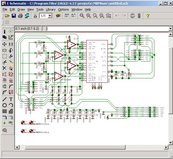
When the prototype was hand-wired, I was having some health problems, and didn't have the time or energy to make "real" PC boards. I have a bit of time now, and have spent the last two days doing an Eagle layout for a 4311 PCB. I'm going to add a "header" board that will handle the regulators, summing amp, and the MIDIBox hookup. This header board will daisy-chain with up to eight 4311 boards for a max of 16 stereo pairs. With a little luck, I'll get these sent off to the boardhouse next week. I use a SLOW boardhouse because they are cheap, so it will be about three weeks before I can test my work. I'm adding an option for plugging in a mic-level inputs, or Phono (RIAA) inputs, or whatever. If the line level boards are well received, I'll add the others later. My eagle files will be available to anyone who wants them. I hope Smash likes them enough to take them, 'cause he can get boards made cheaper than I can. I'll be working on the documents while the boards are being made. I'll try to keep up this time, it's wasy to let plans slip. If anyone has questions or suggestions, now is the time to ask! LyleHaze
-
AC/AC PSU Riddle ??? Outputs both AC & DC!
lylehaze replied to Smithy's topic in Testing/Troubleshooting
It is possible that the power suplpy is just a transformer and bridge, without any capacitor at all. And the bridge may be no more than a single diode! If that is the case, then it would be DC, as the current only flows one way, but it would be a very choppy DC that would have gaps of zero voltage. (if only one diode then those gaps would be more than 50% of the time!) So, take two LEDs, connect them parallel (side-by-side) with one pointing each way, then add an appropriate resistor in series with the pair, and connect it to the output of the power supply. If one lights, it's DC. If both light, it's AC. Let's see if I can manage the drawing as ASCII art: <----*-----|<|-----*----\/\/\/\/\-------> |-----|>|-----| You can use Google to find a resistor calculator for your needs. Have Fun, Lyle [edit] that would look better in a monospaced font. The LED's are supposed to be together.. Oh well, I hope you can make sense of it. -
That is absolutely insane. I must be missing something though, I can't seem to find a price for the kit. I'd love to try something like it using QProx sensors, but they would probably be too low-res. I just think it's be cool to have the whole thing sealed under glass. Still very cool. Lyle
-
Excuse me. Has anyone seen my red swingline stapler?
-
Can you suggest a good example project that mixes C and Asm? LyleHaze
-
Wow. That's a lot going on. So far I've done it all in assembler. I wonder how hard it is to mix ASM and C int he same project? If you move up to 14 bit controls (really just 8) we'll need to re-make the log lookup tables. That's no problem, I did them in Excel anyway. The source in the WIKI is set for eight pairs of stereo right now, but it's REALLY easy to change it to 16 pairs. (I hope) If you want to build the control surface too, there's a choice to make. You can put it all one one core for a complete package, or you can build the controls on another core so you can separate them with a MIDI cable. That might be easier to work with for some jobs. Really you can do both, except that your local pots will be out of sync when you've been controlling the board remotely. Mine is controlled by sequencer, script files, a single local encoder on the mixer, and a Behringer BCR2000, all active at all times. Of course from "inside" the mixer it's one local encoder or MIDI commands. Since it really doesn't know where the MIDI is coming from. (CAMD.library) As with most projects, a display would be a good idea, just so you can see what is going on. Cool Stuff! LyleHaze