lylehaze
-
Posts
613 -
Joined
-
Last visited
Content Type
Profiles
Forums
Blogs
Gallery
Everything posted by lylehaze
-
Yes, I meant Obsessive Compulsive Disorder.. Not quite serious, but not completely sure that I didn't mean it either. I guess I'm just really devoted or something. :-) LyleHaze
-
OK.. Maybe I'm O.C.D. I keep working on this. There is a good chance that "fan out" may not be a problem at all. According to my most recent research, the impedance of these CMOS inputs is so high that they present almost no load at all. It may be that all we need to do as the stack gets bigger is to terminate from the TOP of the stack. The boards start at the bottom: Reg Board, Output Board, first channel board etc. Keep stacking as high as you want. Then, at the TOP of the stack, add a 100k resistor from "Chip Select" to "Digital Ground", and another 100k resistor from "Shift Clock" to "Digital Ground". http://www.midibox.org/dokuwiki/pga:stackboards These should draw just enough current to keep the noise down, and to clean up the signals that the PGA chips see. This is definetly the first thing to try if people start building bigger stacks. I look forward to hearing from people who are building bigger stacks of channel boards. LyleHaze
-
Mutes: Everything today is by software. I joined all the hardware mutes and the Zero-Crossing signals just in case someone wants to play with them. They are currently brought out for selection by jumpers on the output board. Buffer Chip: I looked at a few options. I'm not sure which would be easiest to get/already in stock/cheapest. I think I'll leave this alone for now and let someone else figure it out. I'm in the middle of a job search and it is taking a lot of my time. If I don't get back to work soon there will be no new projects for me at all. ;-) I am favoring a single chip solution, probably piggybacked off of J10, with O.C. outputs. Pullup resistors can then be added to the "top of stack" on those two signals. This termination should provide clean signals all the way up. I wonder if termination at the top of stack would improve the signals even without a buffer? Seems likely. We haven't even figured out how many channel boards we can drive from a "naked" Midibox J10 yet. I'm running four channel boards with no problems at all. I am not an expert in this. I am open for suggestions or discussion. I know I'm not the first to gang too many boards onto a Midibox output. As the core instruction clock is 10Mhz, that means the clock should be able to support 5Mhz as a top speed. That should provide a bit of safety margin. LyleHaze
-
re Buffering: There are many ways. I'll try to look up a part number later today. re Mute and Solo: Not hard to do these in software. I already did separate mutes for each FX out on each channel. Didn't think of mute and solo for the mains though. There IS a hardware mute signal, they are all connected together, and you can attach a pushbutton or switch to force mute anytime you want. It's on a pin header on the output board, and it's passed up through the stackpins to every channel board. LyleHaze
-
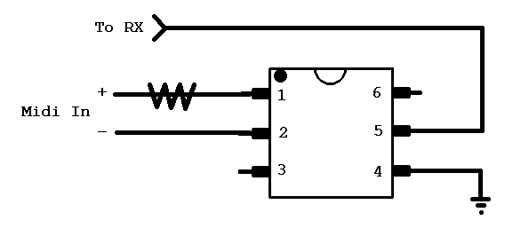
Your pin numbers have 4 and 6 swapped. This might confuse somebody that tries to wire this up. This one has them corrected. Also, this circuit should have a pullup resistor for pin 5 (to RX). It might work without it, but for the price of a resistor, why take chances? Have Fun, LyleHaze
-
Yes, with 25 channel boards you can make it do everything except cook your breakfast. You will be able to mix each signal into any combination of Left, Right, FX1 and FX2. You can even swap left and right inputs per channel as needed. To do this you will need to make a few changes: Hardware will definetly require buffers on the SCLK and CS lines coming from the Midibox. Every channel board will be built for one input to four outputs, just like a "full audio" mixer. Software will require changes so that the MIDI channels that are for the stereo pairs will use 2 channel boards for each pair. There will be a lot of details to work out how that happens. You will modify the Mid2Gain routine (in setlevels.h) to make it behave the way you want. I suggest starting with a few channels, just to get comfortable with the system. Maybe four mono inputs into L,R,FX1,FX2, using the software as it is written. You could then use that as a test bed for making the hardware and software changes. Have Fun, LyleHaze
-
Almost right. The software is limited by 16 MIDI channels. Right now there is just two ways to do each channel: "Line Mixer" takes stereo In, mixes into Left and Right outputs. Uses Volume, Balance, Master Volume, Expression. Each channel board supports TWO stereo pairs. "Audio Mixer" takes Mono in, mixes into Left, Right FX1 and FX2. Uses Volume, Pan, Master Volume,Expression, FX1 Level, FX2 Level, FX1 Pre/Post, FX2 Pre/Post, FX1Mute, and FX2 Mute. Each channel board supports ONE mono input channel. "I've understand we are limited by 16 MIDI channel." The software limit of 16 MIDI channels can be changed. You'll just need to use a different control change arrangement to make it work. Example: Using CC7 for volume (the MIDI standard) only works for the first 16 channels. You can map other CCs if you want, to make this change, you must re-write the "USER_MPROC_NotifyReceivedEvent" part in the file "main.asm". You will also need to expand the size of the "MIDI1 to MIDI16" table and the "CHANNEL_GAIN" table in app_defines.h. ALL of MBMixer is written in ASM, so you might need to study the code first. "One board have 4in to 4out so is it possible to use it as 1 stereo input and 1 stereo output and 2 mono fx out?" If you want to mix a stereo pair into effects outputs, you will only get one channel (left or right) into each of the effects outputs. Right will go to FX1, and Left will go to FX2, I think. If that's what you want, then just set that channel as "full audio mixer" when you configure the software. "And is it possible to use it as 2 mono input and 1 stereo output with 2 mono fx out?" No, you need 2 channel boards to do that. There are 4 level controls on each channel board. Each mono input needs a mix into Left, Right, FX1 and FX2. That uses all 4 of the PGA controls on a channel board. There are 4 inputs and 4 outputs on each channel board to make sure you can always use all 4 of the PGA channels. But mixing all 4 inputs to all 4 outputs is not possible with one PGA4311 chip. Try to think of a channel board as four mono level controls. That is the limit of one channel board. For a "line mixer" we need all four inputs, 2 each left and right. and two outputs, left and right. There are only four levels being controlled. Ch 1 Left, Ch 1 Right, Ch2 Left and Ch2 Right. Each input has only one destination. You can't send a left input to a right output, and nothing is going to the FX sends. For a "full audio" Mixer we use ONE input, and it is mixed into four possible outputs, Left, Right, FX1 and FX2. There are still only four levels being controlled. I hope this helps you understand how the channel boards work. I have been working on an audio flowchart that will better diagram the whole system. "My needs are 9 stereo input and 7 mono input with 2 fx send(if this is possible)." Even numbers work better. Without any changes to the software, you can set up 10 pairs stereo input (5 channel boards) and six mono inputs with FX (6 channel boards). NOTE: ONLY the mono input channels can mix into the FX outputs. NOTE: Using 11 channel boards in one stack may require two of the signals from the Midibox to be buffered. I'm sure there are more questions. This is a great place to discuss it, I'm sure there are other people that want to know the same things. LyleHaze
-
Just a few ideas.. I have not built one of these, but I think I understand the drawing. The way the diodes are drawn, if ANY chip output (from the D2 connection of any core) goes LOW (near GND), then ALL the inputs(d3) will read LOW. I don't know if you are using separate cores or if they are all on one board, but if they are separate, this will only work if they all have the same ground. Check that. Next thought.. if the (d2) output of any core stays LOW, NONE of the boards can talk, which would probably look like a CAN bus error. Pardon the stupid question, but is the software loaded on ALL the cores? Are ALL of them set up to use CAN comms? If ANY of the attached cores doesn't know it's supposed to be doing CAN, then they will all get confused. Finally, didn't the CAN pins used to be used for the LCD display? Are ALL of the cores set up for either 4 bit LCD or no LCD at all? If a core is trying to display "Hello World" through the 8 bit LCD port, your CAN stuff will get knocked out. But like I said, I have no experience with this project, I'm just guessing. Good Luck, LyleHaze
-
The CAN standard applies when every node is using a CAN transciever chip. In that case, you need a 120 Ohm resistor at each end of the run. The drawing shown here is NOT the standard for CAN. It's a diode-AND configuration. It uses less parts (no transciever chips) and should work great for LOCAL wiring. It will NOT be as robust over long distances as proper CAN chips can do. Just my two cents, if I'm wrong, please correct me. LyleHaze p.s. ribbon cable can lead to signal crosstalk. try running CAN on a separate wire to see if that helps! When CAN transciever chips are used, the differential input section reduces a lot of that kind of noise.
-
strophlex: from the "Project purpose and intent" One of the best things about this new mixer is that there is no control surface. I have found it incredibly better to keep the C.S. separate. By separating them, you can put the audio "backend" at the stage, where the signals are created and the amplifiers are fed. You can move the controls to the other end of a MIDI cable. You have just eliminated dozens of shielded audio cables running from the stage all the way up to the mix booth. All the audio stays backstage where it belongs. Even better is for a studio environment. I have my control surface and my MBMixer plugged in to separate MIDI ports on my computer. They are patched together in software. So I always have full manual control, but I can also record a "dynamic" mix with a sequencer, and play it back as easily as any other MIDI track. I also have an on screen mixer that is fully functional, and a few hotkeys on my PC keyboard that my wife requested for muting the system. (or turning it WAY FREAKING UP!) To answer your question: You might be able to put an LC and a MBMixer on the same core, but you would get better results if you make them separately. But you are right, you really need a good C.S. to have fun with the mixer. LyleHaze
-
I really need to start a new thread. MB stor is a new project. I added it to my mixer, but it can be separate. It's really simple, and the hardware is already built. See http://www.vinculum.com/prd_vmusic1.html It is: an MP3 player, a .wav player, and it plays format 0 midi files too, with it's own internal voices. It also handles the filesystem of a USB stick. Programs can open files for reading or writing. The filesystem is very much like a DOS command line. (CD, DIR, MD etc). Right now it plugs into J6 and J7, so no motorfaders and no multiplexed AIns available. The current state of the software just passes all commands in and out by SysEx messages, so I can experiment from a command line. Once I get time, I'll probably write a MIDI file player that plays the file to the MIDIBox MIDI out, I will then release it all. Right now all my code is in ASM. I'm hoping to re-write most of it in C and release it as a proper module. This will take some time. It's a fun toy. LyleHaze
-
I have not yet merged the mixer software with anything except MB-Stor. Since the mixer uses J10, there should be no conflict with the MotorFader modules. writing to the mix array does require disabling DIN/DOUT scans for a few ms though. That's really the only compromise I can think of right now. MB-Stor does require J6 and J7, so it cannot be used with Motorfaders. But that's another project. I have not posted the board designs to try and prevent seeing my mixer for sale on E-Bay. If anyone is interested in boards, please express your interest to SmashTV. If he hears from enough people, he might decide to carry the boards in his webshop. If that doesn't work out, I will need to find someone who wants to organize a bulk order. I can't. I'm broke and unemployed. Thanks for your interest (Yes, the mixer sounds great, I'm listening to it now). Any interest in a MIDI controlled MP3 player? I installed one of those in the mixer last week. It comes with a 8 Gig bankstick :-) LyleHaze
-

DIY audio patchbay with digital routing....How hard?
lylehaze replied to Nomical's topic in Design Concepts
How hard would it be for the matrix to talk to MB Mixer so that if I had 16 inputs on the MB Mixer connected to 16 outputs of the matrix, the mb mixer would display what source was coming in from the matrix? this would then update if the matrix patch was switched? Could probably be done with SysEx? That would be a really slick level of integration. just a thought, The MBMixer does support named channels. It's one of the first things I added. At this time, it does not allow changing the names by SysEx. There's no reason why it couldn't do it though, there are flash read/write routines already in use for the preset management stuff. The question would be, do you burn every name change into flash, or would it be better to keep them all in RAM, and expect them to be initialized after every reset? I guess some combination of the two would be best. So your answer, not yet, but it can be added. :-) LyleHaze -
I am interested. After seeing the 5X5 board, I regret missing out on the order for the USB interface boards and chips. It will be at least a few months before I can find any money for toys. For design details, activity LED's for each jack would be good. I noticed there are just two bypass caps for all four optos, and they aren't particularly close to any of them. I suppose I could add a flying cap at each chip myself. Looks great. I already have a 8X8 USB interface, but at the right price, these could be useful! Now that Edirol has stopped making the UM-880 and UM-550, there is a need for something like this. LyleHaze
-
>Nothing can be uploaded into my core module.... >there is no way.... >I have tried with mios in 3 ways >1) waiting for an upload request (that never arrive) >2) smart mode without results >3) manual mode (with this one i get upload succeded but i don't see changes neither to the display) Manual mode will always succeed, because it's not checking to see if it got there. >I can see the first row light and the second row dark. That means nothing is talking to the display. You probably need to burn the bootloader into the PIC again. It does not appear to be running Your power readings look good, I assume your 7805 is not burning hot. If your crystal is OK, then you are down to a blank PIC or a bad PIC. PIC's are usually pretty tough. But I'm just guessing. Good Luck, LyleHaze
-
Your questions have me looking the SID module over. Instead of answers, I have more questions. You mentioned using this with the MBMixer. Yes, it will work with that. But the MBMixer has support for balanced inputs and outputs already. It has had balanced support for almost four days now! :-) (ok, I have got that off my chest, back to your questions) Question 2 asks if you would need to attenuate the input level before going into the SID. Wow, I never knew the SID had an input! As a rule, inputs may never exceed the voltage range of the chip. So what's your chip running at? Depending on the model, either 0 to 9 or 0 to 12 volts. So ASSUMING that the audio input is biased between 0V and +9 or +12 V,(a fair assumption after seeing the schematic) you must keep the peak to peak voltage of the input below 9 or 12 volts. You mentioned that you are taking + and - 15 volts into your SID.. but the prints I saw only showed +5 and either +9 or +12, depending on the model. Maybe I saw the wrong schematics. So my assumption above may be wrong. Is this Sid Ver 2 based on the Sid board that Smash sells at his shop? I don't see any negative voltages there. (He's a really positive guy that way). If it's something else, where can I see a drawing? Will your design provide Phantom power if needed? If you are looking for the most options, you might want to include that one. Looks interesting! LyleHaze
-
All: The WIKI has been updated with the latest docs. Lots of photos and drawings have been added. The source code to MBMix ver 2 is there, as well as the source to configmixer, lots of assorted help files, and the most complete build guide I have written yet. If you're interested, please take a look http://www.midibox.org/dokuwiki/midiboxmixer as always, comments are welcomed. LyleHaze[me=lylehaze]is tired of typing.[/me]
-
ilmenator: Thanks for the reply. I tried it again in the playground, no luck. When I "Add Image and Other files" I get a namespace selector. I am allowed only to use files already in my namespace. Unless maybe I have rights in the MBMix space that I do NOT have in the playground. I'll get back to you on that. Thanks Again, LyleHaze [edit] I tried the playground and the MBMixer docs, with Firefox and IE6. I can edit text and include existing images, but I cannot upload new ones. I'm going to cut and paste hte new docs into the WIKI (text) and add the pictures after I get them uploaded.. Thanks Anyway!
-
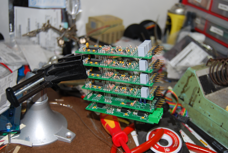
While I'm waiting for some uploads to the WIKI, I thought I'd post a picture. This is a stack of (from the bottom), 1 regulator board, 1 output board, and four channel boards. These are built for a "Line Mixer" with unbalanced inputs, you can tell because each channel board has four input caps. If you look close, you'll see the output board is only populated for two output channels, meaning no effects loops here. The stack fits well inside a 1U rack mount case. This was a requirement of the original design.
-
I am happy to announce that Version 2 of the MidiBox Mixer is now ready. Circuit boards have been designed and tested. The new software is ready. As described previously, we now support optional Effects Loops, balanced and unbalanced inputs and outputs, save and load up to 64 full banks of presets, Effects pre/post switching (even on the fly!). MIDI support for Volume, Balance/Pan, Expression, Master Volume, effects muting, channel and bank load and save, and a command to transmit all current settings, to support C.S. synchronization or algorithmic manipulation. Also included is ANSI C source for a command-line program to easily create MIDI files that can configure or preset the mixing board. This is a MIDI controlled analog audio mixer. It is completely "solid state". It has no pots or sliders, and so it should never get "scratchy" with age. The audio path is all analog. The audio signals are never digitized. It can be configured for any combination of line level and high impedance inputs, balanced or unbalanced, as you wish. It is modular and expandable. so everyone gets to do it their own way. I have zipped all the files for this project into a single file, including documentation in HTML format. It is under 3 Meg in size. So far I have been only clumsy in editing the WIKI. I'll try to get this file uploaded, or I'll ask for help like I did last time. The new file is MBMixV2.zip. I want to thank everyone for your patience as I have worked through all the details. Please post any questions or comments here in the forum if possible. Make Beautiful Music, LyleHaze [edit] file attachments in this forum are limited to 1 Meg. The best place to put it is in the WIKI, but I can't figure out how to add new files to my namespace. Suggestions would be welcomed.
-
Midi explanation in Hex for those asking how to edit .ini files
lylehaze replied to Bassman's topic in MIDIfication
JimHenry: I was referring to my understanding of the MIDI spec. I have no knowledge of the MIDIO128 or how it handles things. Sorry if I was off-topic or misleading. Regarding options for note-on and note-off, I'll suggest a programmers response: The sender may use either, the receiver must deal properly with both. For my own projects, as MIDI input is first handled, any note-on with a velocity of zero immediately gets bit 4 of the status byte reset. This makes life a lot easier for the code that follows. But we each get to do it our own way, as long as every receiver can handle both, every sender can do as they wish. I can't imagine a pitch bend value that shifts both seven bit values separately. There would be only seven bits of resolution that way, but then, I can't rule out that some idiot has done it that way. True, the MMA is just the governing body that writes the MIDI standard, we are under no obligation to follow their rules, as long as we have no interest in calling our products "MIDI". I'll continue to follow their rules. Have Fun, LyleHaze -
Midi explanation in Hex for those asking how to edit .ini files
lylehaze replied to Bassman's topic in MIDIfication
JimHenry: Close, but not quite. an on/off control handled by 0-127 would be <64=OFF, >63=ON. It makes more sense if you see the values in binary. The most significant bit is the On/OFF switch. So any value of 64 or above is ON. To center a 7 bit value, such as balance or Pan, the valid range is 1 to 127, with 64 as center. Input values of zero should be converted to 1. (ref www.midi.org/techspecs/rp36.php) To center a 14 bit value, you don't set both bytes to 64, just the most significant one (coarse). So Coarse to 64, fine to 0 for center position. LyleHaze -
How are any of you managing to finish your mb-6582's?!!!
lylehaze replied to dubka's topic in MIDIbox SID
@SLP: I just ordered 200 of these: http://search.digikey.com/scripts/DkSearch/dksus.dll?lang=en&site=US&keywords=0.0ebk-nd Might that do? ;-) Funny, they cost MORE than regular resistors. And since dissipation is based on resistance, how much current would exceed the 1/6 watt rating? LyleHaze -
I made some progress. I tried it my way, and the mixer died. No controls, no display, not good. I must have been doing something inside that section that is shut down by MIOS_SystemSuspend. So I tried it TK's way, now it works like a charm. Thanks, TK! (apparently this TK guy knows MIOS pretty well) :-) This saves me from having to support alternate interface ports for those who want lots of PGA channels attached. Happy Happy, back to software testing. LyleHaze
-
I'm still looking for better ways to solve this. I may have found something in the function reference. The problem: I need to disable interrupts for slightly longer than a few bytes at MIDI_BAUD, so that MIOS will not try to scan DIN and DOUT while I'm transmitting. J10 shares pins with DIN and DOUT, as well as my hardware. Disabling interrupts for more than one byte-time may cause a loss of data from MIDI_IN. Perhaps a better solution: Can I use MIOS_System_Suspend and MIOS_System_Resume instead of disabling interrupts? If I am correct, this will forbid IO scanning without locking out the serial port handler. Is this right? Since my app makes very little use of DIN, and NO use of DOUTs, a few ms of delay is a much better option than giving up the analog ports. Thanks, Lyle